In modern industrial processing, the cost of an unplanned batching failure extends far beyond the price of a replacement component. When a batch is inaccurately dosed, it results in off-spec products, expensive chemical rework, regulatory non-compliance, and severe production bottlenecks. Maintaining absolute repeatability requires a rigorous approach to fluid dynamics, electromechanical timing, and wear mitigation.
A proactive preventive maintenance program for Liquid Batching Systems is not merely a recommendation; it is an engineering necessity. High-cycle automated dispensing—particularly with varying viscosities like diesel, transmission fluids, and heavy motor oils—places immense stress on gear tolerances, pump seals, and solenoid valve diaphragms. By standardizing calibration checks and component inspections, plant managers can ensure that every preset volume is delivered with zero drift.
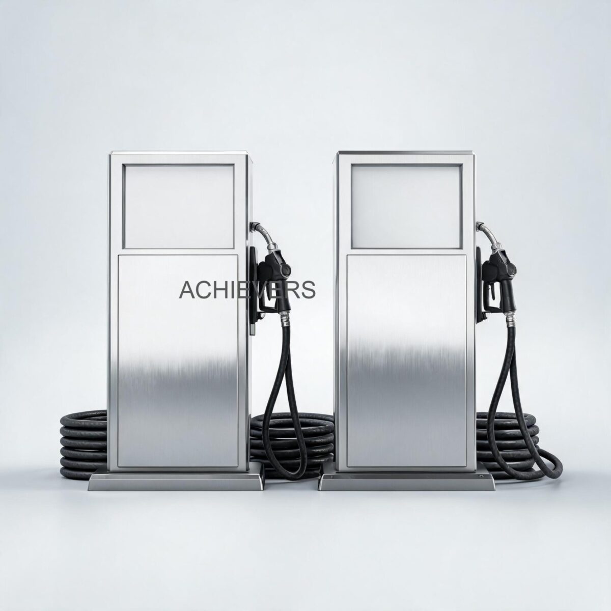
This technical guide serves as a comprehensive maintenance framework for industrial Liquid Batching Systems. We will analyze the critical wear parts of the oval gear metering unit, the electromechanical delays in solenoid control, and the mechanical health of the transfer pump. Whether your facility is an automotive assembly plant filling crankcases or a chemical processing unit managing additive dosing, these engineering protocols will maximize your system's operational lifecycle and measurement integrity.
1. Product Overview and Critical Wear Components
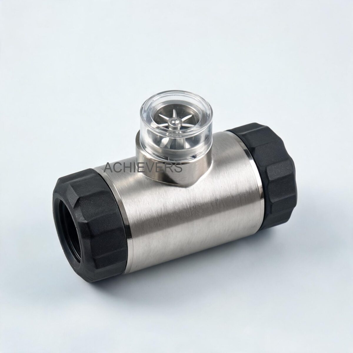
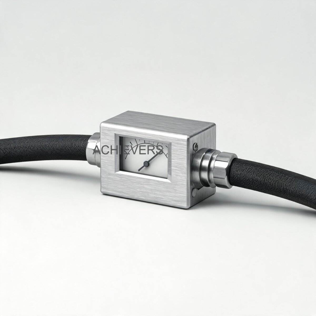
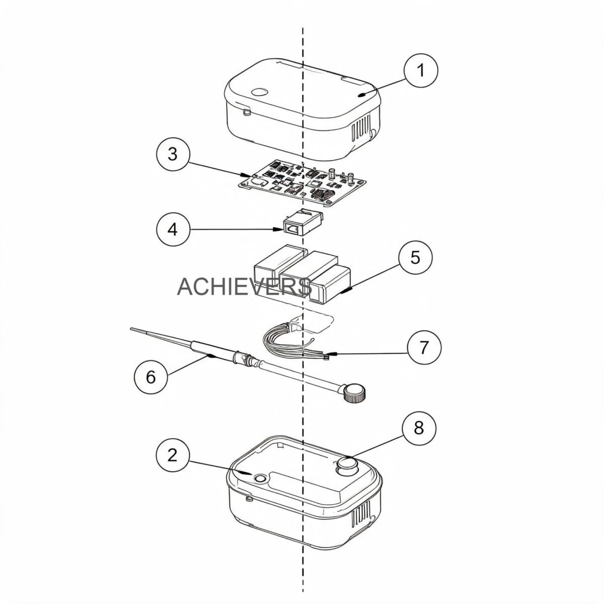
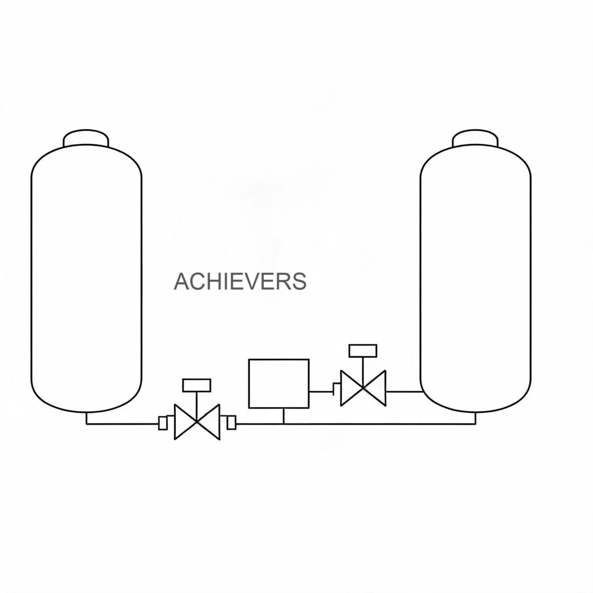
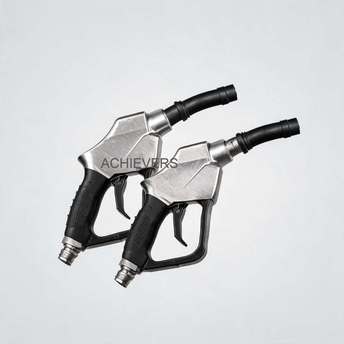
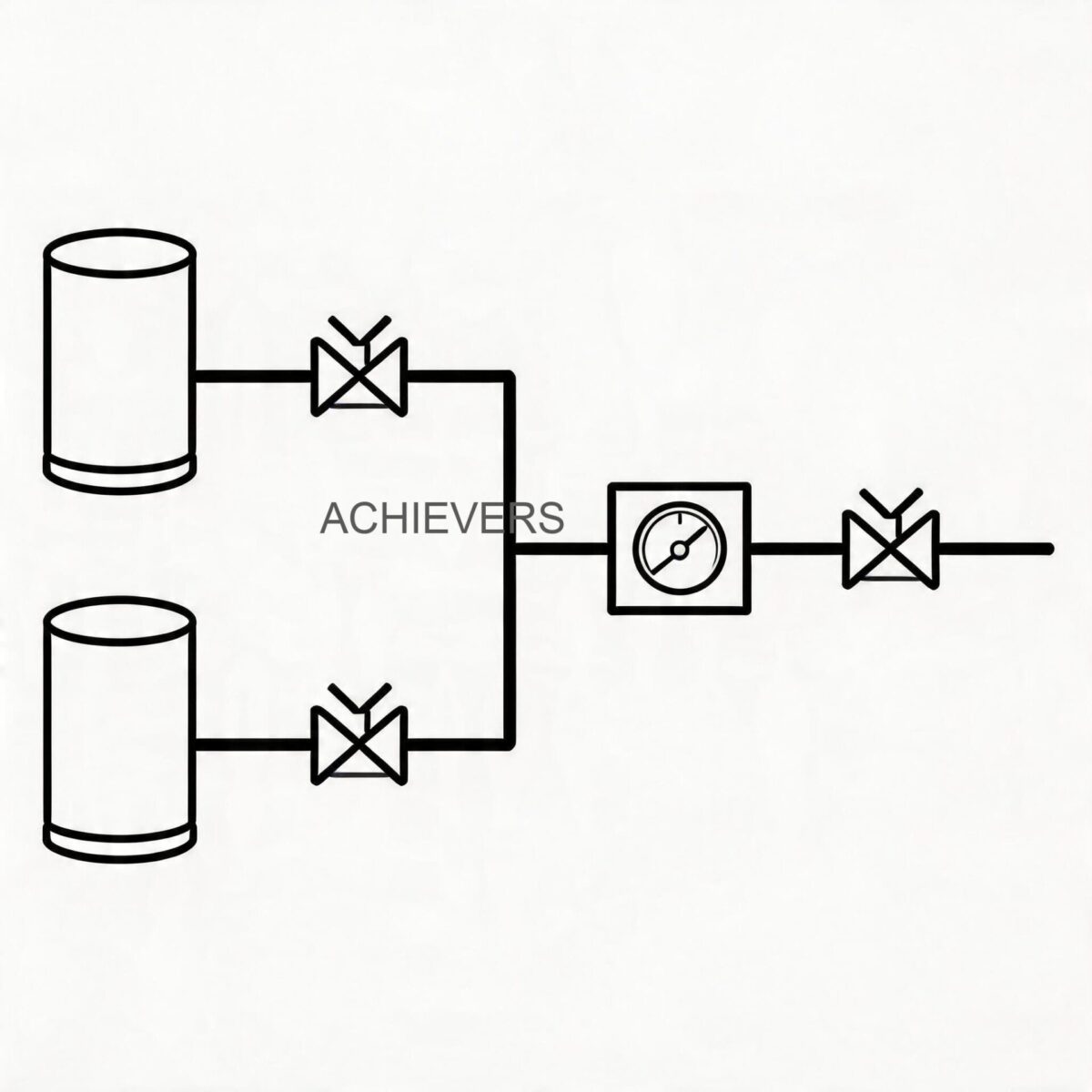
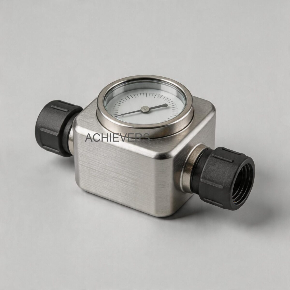
At the core of these Liquid Batching Systems is a highly engineered electromechanical loop designed for maximum endurance and low support requirements. The system integrates a continuous-duty transfer pump, an oval gear flow meter (a type of positive displacement meter), an electronic batch controller, and a fast-acting solenoid valve.
Based on the precise technical specifications of the Achievers brand units, the operational parameters are defined as follows:
- Maximum Volumetric Capacity: 60 Litres/Min
- Base Accuracy Rating: ±0.5 %
- Power Requirement: 220 V AC
- Primary Measurement Technology: Oval Gear (Positive Displacement)
- Viscosity Capability: Ranges from light diesel up to maximum thickness motor and transmission oils
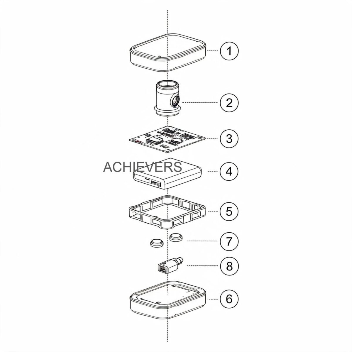
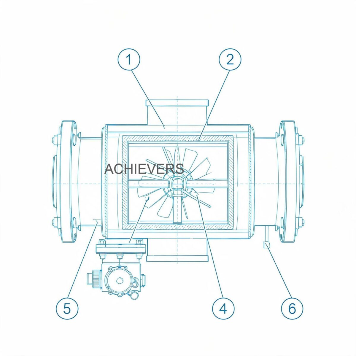
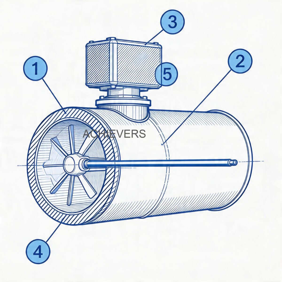
The primary wear components in this architecture are the oval gears and their central bearings. Because positive displacement meters rely on the fluid to drive the measuring elements, particulate contamination or fluid starvation can cause micro-abrasions on the gear teeth. Over time, this increases the mechanical clearance (slip) between the gears and the measuring chamber wall, leading to under-registration of highly viscous fluids. The solenoid valve, responsible for cutting off flow the millisecond the preset volume is reached, is also subjected to continuous hydraulic shock and requires regular inspection of its pilot orifice and sealing diaphragm.
2. Technology Comparison Table and Decision Matrix
To understand why oval gear technology is selected for this system over other methodologies, engineers must evaluate fluid characteristics against measurement principles. Below is a comparative analysis of oval gear technology versus other common flow measurement methods used in batching.
| Parameter | Oval Gear (Positive Displacement) | Electromagnetic Flow Meters | Turbine Flow Meters |
| — | — | — | — |
| Working Principle | Volumetric displacement of fluid | Faraday's Law of Induction | Kinetic energy of fluid turning a rotor |
| Best Fluid Match | High viscosity (Oil, Diesel, Lube) | Conductive fluids (Water, Chemicals) | Low viscosity, clean liquids (Water, Light fuels) |
| Viscosity Limits | Excellent (Accuracy improves with thickness) | Unaffected by viscosity | Poor (Performance drops with high viscosity) |
| Standard Accuracy | ±0.5% | ±0.2% to ±0.5% | ±0.5% to ±1.0% |
| Straight Pipe Run Req. | None required | 5D upstream, 3D downstream | 10D upstream, 5D downstream |
| Moving Parts | Yes (Rotors/Gears) | None | Yes (Rotor and bearings) |
| Maintenance Frequency | Moderate (Gear wear, filters) | Low (Electrode cleaning) | High (Bearing replacement, calibration) |
When to Use This Technology (Decision Matrix)
- Choose Oval Gear Batching Systems: When dispensing viscous, non-conductive fluids like transmission fluid, motor oil, and diesel fuel at variable flow rates. Ideal for tight installations without straight pipe runs.
- Choose Electromagnetic Systems: When batching highly corrosive aqueous chemicals, wastewater, or food-grade conductive slurries where zero pressure drop is mandatory.
- Choose Turbine Systems: When batching high volumes of ultra-clean, low-viscosity liquids (like light solvents) where long-term steady-state flow is expected.
3. Engineering Formula and Calibration Note
Achieving ±0.5% accuracy at 60 Litres/Min requires compensating for the mechanical response time of the solenoid valve. In high-speed batching, there is an inherent delay between the controller sending the stop signal and the solenoid valve completely closing.
Calibration Formula for Batch Overrun:
Actual Volume = (Total Pulses / K-Factor) + Overrun Volume
Where:
- Total Pulses: The number of electrical pulses generated by the Hall effect sensor.
- K-Factor: The number of pulses per litre (e.g., 100 pulses/L).
- Overrun Volume: The fluid that passes through the valve during the milliseconds it takes to fully actuate.
Engineering Calibration Note: If you notice consistent over-batching of 0.1 litres on a 50-litre preset, do not immediately alter the meter's mechanical K-factor. Instead, adjust the Advanced Preset Controller's pre-actuation value (or slow-close parameter). Program the controller to drop power to the primary solenoid coil slightly before the target volume—for instance, at 49.9 litres—allowing the hydraulic momentum to perfectly coast to 50.0 litres.
4. Preventive Maintenance Schedule
Under heavy industrial duty cycles, components degrade predictably. Adhering to the following maintenance table prevents catastrophic failures and ensures ISO compliance for product dispensing.
| Maintenance Task | Frequency | Responsible Personnel | Est. Time | Engineering Notes |
| — | — | — | — | — |
| Visual Leak & Housing Inspection | Daily | Plant Operator | 5 mins | Check pump shaft seals, meter flanges, and solenoid fittings. |
| Strainer / Filter Blowdown | Weekly | Maintenance Tech | 15 mins | Clogged filters cause pump cavitation and gear starvation. |
| Pump Motor Current (Amp) Draw | Monthly | Electrical Engineer | 10 mins | High current indicates bearing wear, fluid too cold/viscous, or blocked filter. |
| Pre-Set Controller Output Test | Monthly | Instrumentation Tech | 15 mins | Verify 220 V AC pulse reaches the solenoid instantly. |
| Volumetric Proving / Calibration | Quarterly | Quality/Metrology | 60 mins | Use certified volumetric proving cans. Adjust K-factor if drift exceeds ±0.5%. |
| Gear Chamber Flushing | Bi-Annually | Maintenance Tech | 45 mins | Flush with light solvent to remove metallic sludge and hardened additives. |
| Solenoid Diaphragm Inspection | Bi-Annually | Maintenance Tech | 30 mins | Check for tear, elastomer degradation, and pilot hole blockage. |
| O-Ring and Seal Replacement | Annually | Maintenance Engineer | 60 mins | Replace all dynamic seals regardless of visible wear. |
| Oval Gear / Bearing Micrometer Check | Annually | Mechanical Engineer | 90 mins | Measure gear tooth clearance against factory spec. Replace if out of tolerance. |
| Electrical Terminal Re-torquing | Annually | Electrical Engineer | 20 mins | Vibration loosens connections, causing intermittent signal drops and batch errors. |
5. Step-by-Step Procedures for Key Tasks
Procedure 1: Upstream Strainer and Filter Cleaning
A blocked strainer is the leading cause of flow meter inaccuracy and pump cavitation. The oval gears require a steady, non-turbulent column of fluid to maintain the ±0.5% accuracy.
- Power isolation: De-energize the 220 V AC system at the main breaker to prevent accidental pump start-up.
- Hydraulic isolation: Close the upstream and downstream manual isolation valves to lock out the fluid pressure.
- Pressure relief: Carefully open the bleed valve or cautiously loosen the strainer cap to relieve trapped line pressure.
- Cap removal: Unbolt the strainer housing cover. Inspect the housing O-ring for flattening or chemical degradation.
- Basket extraction: Remove the stainless-steel mesh basket. Note the type of debris (e.g., metal flakes suggest upstream pump wear; sludge suggests degraded oil).
- Cleaning: Wash the mesh basket in a compatible solvent. Use compressed air (blowing from the outside in) to dislodge embedded particles. Do NOT use wire brushes that can alter the micron rating of the mesh.
- Reassembly: Insert the clean basket, install a new housing O-ring (lubricated lightly with the process fluid), and torque the bolts in a star pattern.
- Purging: Open the upstream valve slightly to flood the housing and purge air through the bleed valve before fully reopening the system.
Procedure 2: Oval Gear Meter Inspection and Sensor Cleaning
If the controller displays erratic flow rates or fails to register flow while the pump is running, the oval gear chamber must be inspected.
- Isolate and drain: Lock out the electrical supply and isolate the hydraulic lines. Drain the metering unit completely into a safe receptacle.
- Sensor removal: Unscrew the Hall effect pickup sensor from the top of the meter body. Inspect the tip for accumulated ferromagnetic debris and wipe clean with a lint-free cloth.
- Faceplate removal: Remove the hex bolts securing the front cover of the measuring chamber. Pull the cover off evenly to avoid binding on the alignment pins.
- Rotor extraction: Carefully slide the two oval gears off their central shafts. Note their orientation; many gears have a specific timing mark that must align during reassembly.
- Chamber inspection: Illuminate the internal measuring chamber. Look for deep scoring on the chamber walls or backplate, which indicates particulate damage and excessive fluid slip.
- Bearing check: Rotate the bearings inside the oval gears. They should roll smoothly without lateral play. If using carbon or ceramic bearings, look for hairline fractures.
- Re-timing and assembly: Reinstall the gears, ensuring they are perfectly meshed at a 90-degree offset. Rotate them manually; they must turn freely with zero binding.
- Sealing: Install a new PTFE or Viton faceplate seal, replace the cover, and torque the bolts sequentially to the manufacturer's specified torque rating.
6. On-Site Spare Parts to Stock
Supply chain delays for critical instrumentation parts can halt automotive assembly lines or fluid packaging plants. Maintaining an on-site inventory of fast-wear and critical path parts is mandatory for high-uptime operations.
| Part Description | Component Type | Recommended Qty | When to Replace |
| — | — | — | — |
| Stainless Steel Strainer Mesh | Consumable | 2 per unit | When mesh is torn or cannot be fully cleaned. |
| O-Ring & Gasket Seal Kit | Consumable | 3 sets | Annually, or whenever the meter housing is opened. |
| Hall Effect Pickup Sensor | Electrical | 1 per unit | If flow is present but the controller registers zero pulses. |
| Solenoid Valve Diaphragm Kit | Mechanical Wear | 2 sets | If the valve fails to shut off tightly or chatters. |
| Oval Gear & Bearing Set | Critical Spare | 1 set per unit | If accuracy drift cannot be corrected via controller K-factor calibration. |
| 220V Solenoid Coil | Electrical | 1 per unit | If the coil burns out due to voltage spikes or overheating. |
7. Diagnosing Maintenance-Related Failures
Even with rigorous preventive maintenance, environmental factors or fluid contamination can cause operational anomalies. Use this diagnostic matrix to trace symptoms back to root mechanical or electrical failures.
| Failure Symptom | Probable Cause | Corrective Action |
| — | — | — |
| Consistent Over-Batching | Solenoid valve closing too slowly or debris under the diaphragm | Clean the solenoid pilot hole and replace the diaphragm. Adjust pre-actuation settings. |
| Erratic / Skipping Flow Display | Ferromagnetic debris on the magnetic pickup sensor tip | Remove the sensor, wipe the magnetic tip clean, and flush the gear chamber. |
| Pump Running but Zero Flow Registered | Oval gears locked by solid particulate, or sheared pump coupling | Open the meter chamber, clear the obstruction. Verify the mechanical integrity of the pump shaft. |
| Gradual Loss of Accuracy (Under-Batching) | Gear wear leading to increased fluid slip inside the chamber | Recalibrate K-factor. If wear is excessive, replace the oval gears and bearings. |
| High Noise / Chattering from Pump | Cavitation due to blocked suction strainer or high fluid viscosity | Clean upstream filters. Ensure fluid temperature is high enough to maintain pumpable viscosity. |
| Controller Display Dead | 220 V AC power surge or blown internal glass fuse | Verify incoming line voltage. Replace internal controller fuse and install a surge protector. |

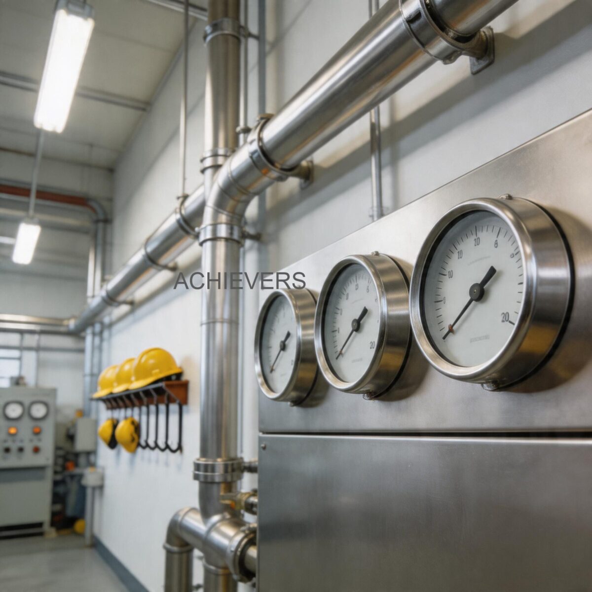
8. Extending Service Life in Harsh Operating Conditions
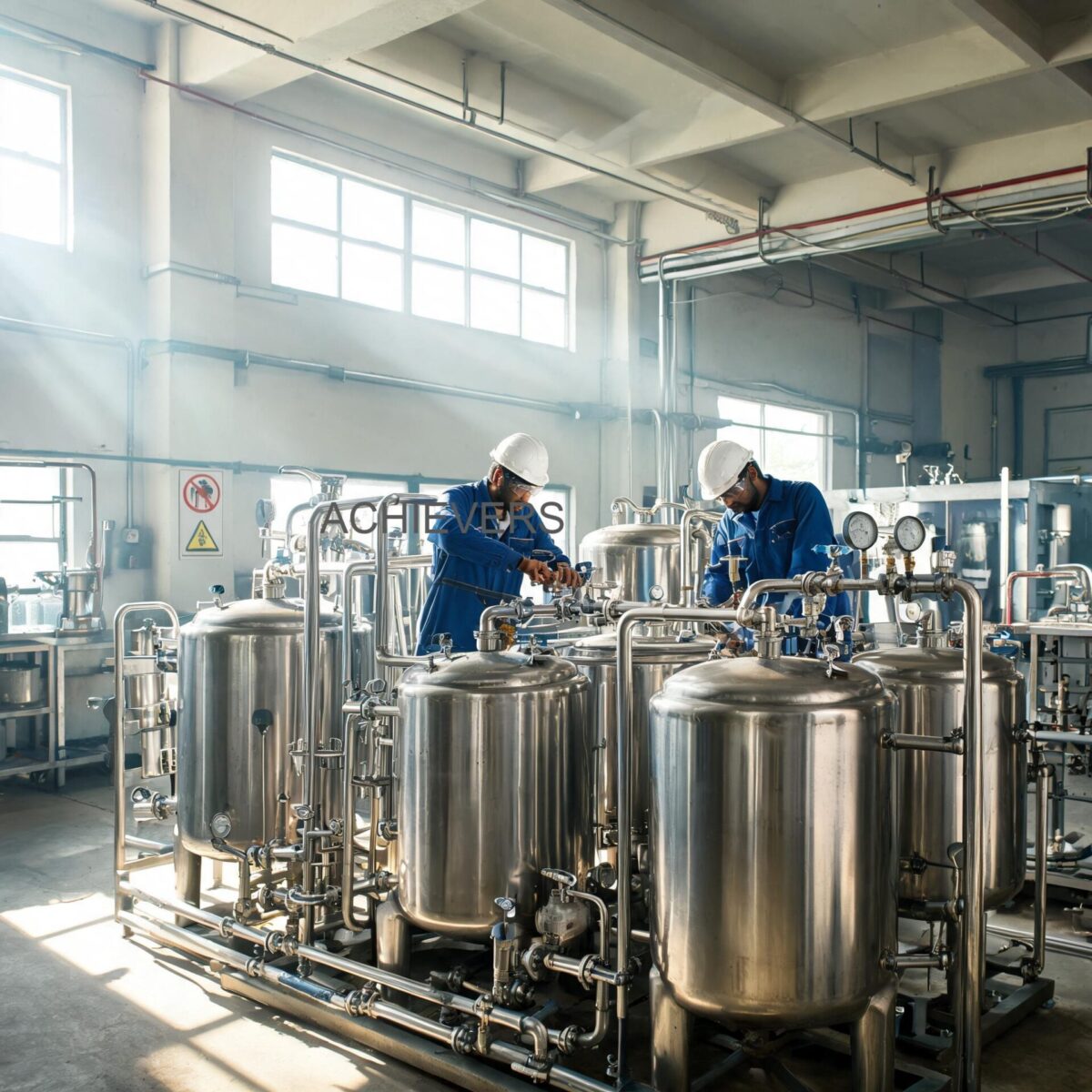
Industrial flow measurement equipment often operates in severe environments. From offshore oil platforms dealing with saline atmospheres to heavy mining facilities contending with extreme dust, operators must adapt their maintenance strategies to the operating theater.
Managing High Ambient Temperatures
In regions like the Middle East or in heavy metallurgical plants, ambient temperatures can exceed 50°C. High heat lowers the viscosity of oils and fuels, potentially increasing slip past the oval gears. Calibration should be performed at the actual operating temperature, not at a baseline 20°C. Furthermore, prolonged heat degrades the potting on the solenoid coils; ensure the unit has adequate shading and ventilation to prevent coil burnout.
Mitigating Power Quality Issues
Industrial grids frequently experience severe voltage sags and spikes, especially when large inductive loads (like heavy compressors) start up on the same network. Because the batch controller relies on precise microprocessor timing, power fluctuations can cause it to miss pulse counts or drop the 220 V AC signal to the solenoid prematurely. Installing an industrial-grade UPS (Uninterruptible Power Supply) and isolation transformers will protect the batch controller's motherboard and ensure ±0.5% accuracy is maintained regardless of grid stability.
Handling High-Viscosity and Contaminated Fluids
When batching recycled motor oils, transmission fluids, or heavy bunker fuels, particulate contamination is a constant threat. Cold startups are particularly dangerous; if the fluid is highly viscous due to low temperatures, the pump will struggle to pull the liquid, leading to cavitation and severe mechanical strain on the oval gears. Implement heat tracing on the piping and ensure the fluid is within the optimal kinematic viscosity range before initiating a high-speed 60 L/Min batch. For heavily contaminated fluids, upgrading to a dual-stage filtration system (a coarse Y-strainer followed by a finer basket strainer) will drastically prolong the life of the positive displacement metering elements.
FAQ
Q: How often should we physically prove or calibrate our batching system?
A: For standard industrial oils and non-custody transfer applications, a quarterly calibration check using a certified volumetric proving can is sufficient. If the system is used for critical chemical blending or packaging for retail sale, monthly verification is highly recommended.
Q: Can this batching system handle water or water-based chemicals?
A: Oval gear meters are generally designed for lubricating fluids like diesel and oils, which naturally lubricate the internal gear bearings. For water-based chemicals, a magmeter, such as Electromagnetic Flow Meters, is the technically superior choice due to the lack of moving parts and resistance to corrosion.
Q: Why does the batch occasionally overrun the preset target by a few decilitres?
A: Overruns are almost always caused by mechanical delay in the solenoid valve closure, known as water hammer or hydraulic momentum. Adjusting the "slow close" or "pre-actuation" parameter in your electronic controller allows the valve to shut slightly before the target, letting the fluid coast perfectly to the preset.
Q: Is it safe to operate the pump continuously without flow?
A: No. Operating the transfer pump against a closed solenoid valve without an internal bypass or pressure relief mechanism will rapidly dead-head the pump. This causes extreme heat generation, cavitation, and eventual failure of the pump seals and motor windings.
Q: How do we compensate for changes in fluid temperature during the day?
A: Temperature changes alter fluid viscosity and volume. Because this system measures absolute displaced volume, a drop in viscosity (due to heat) might marginally increase gear slip. For ultra-precise operations, you must either maintain strict temperature control of your storage tanks or apply a mathematical volume correction factor based on the fluid’s coefficient of thermal expansion.
Q: What is the maximum pressure rating for standard maintenance procedures?
A: Maintenance should only be performed when the system is completely depressurized (0 bar). Operational pressure limits depend on the specific flanges and pump model utilized, but standard industrial systems typically operate between 3 to 10 bar. Always refer to the nameplate data before initiating high-pressure transfers.
Q: Why is the flow rate fluctuating wildly on the controller display?
A: Fluctuating flow rates are typically caused by air entrainment in the fluid (often from a leak in the suction line), a partially clogged upstream strainer causing pump cavitation, or a loose wire on the magnetic pickup sensor sending erratic pulse trains to the controller.
For expert technical support, system sizing, or to request a customized quote, please contact our engineering team with your required product specifications, target flow rate, fluid viscosity, and site operating conditions. Our specialists are ready to help you configure the exact system required to optimize your industrial batching process.