
Selecting the ideal flow measurement technology for process liquids, hydrocarbons, and utility water is a critical engineering decision that dictates long-term plant efficiency and material balance accuracy. Welcome to the definitive engineering guide on Turbine Flow Meters. When dealing with light to medium viscosity fluids—such as diesel, furnace oil, heavy oil, and non-acidic process liquids—instrumentation engineers frequently evaluate the trade-offs between inline and insertion Turbine Flow Meters. Both configurations leverage the same fundamental kinetic principles but offer vastly different performance profiles regarding pressure drop, line size scalability, and volumetric accuracy.
Specifying the correct Turbine Flow Meters requires analyzing process variables far beyond simple flow rate. To eliminate specification errors, this guide breaks down the critical engineering parameters—including Reynolds number limitations, pressure/temperature boundaries, straight-run conditioning, and PLC integration (such as an RS485 turbine flow meter for PLC integration).
1. Overview of the Turbine Flow Meters Family
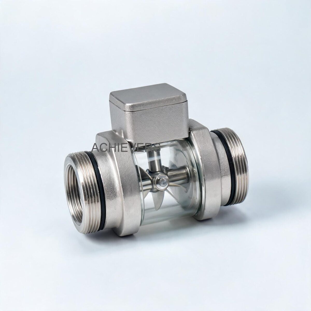
The fundamental principle of operation relies on extracting kinetic energy from the fluid stream. The flowing liquid is accelerated and conditioned by the meter's straightening section. These integrated straightening vanes prepare the liquid flow profile by mitigating undesired swirl, turbulence, and asymmetry before the fluid strikes the turbine wheel.
The dynamic forces of the conditioned fluid cause the rotor to rotate at an angular velocity directly proportional to the fluid's linear velocity. The rotor is mounted on a hard Stainless Steel-316 main shaft equipped with special high-precision, low-friction carbon bush bearings to ensure minimal mechanical drag.
As the turbine blades pass a proximity probe (variable reluctance or active sensor), pulses are generated. By integrating these pulses over time, totalized volume and instantaneous flow rates are calculated. Modern systems offer diverse data acquisition methods, from simple pulse arrays to advanced industrial control networks.
Inline vs. Insertion Configurations
- Inline Configuration: The entire meter body is flanged or threaded directly into the piping spool. The fluid is forced through the precision-machined bore, ensuring all fluid interacts with the turbine blades. This yields the highest accuracy (+/- 0.5% or 1% FSD) and high repeatability (0.1%).
- Insertion Configuration: A smaller turbine rotor is suspended at the tip of a probe and inserted into the pipe (often via hot-tap) to measure point velocity at the pipe's center or critical mean depth. While more economical for massive pipe diameters (>300 mm), it sacrifices accuracy and requires complex Reynolds number profiling to estimate full-pipe flow.
2. Head-to-Head Specification Comparison
To provide a comprehensive industrial turbine flow meter specifications comparison, we must contextualize turbine technology against both its internal variants and competing technologies. Turbine Flow Meters excel with clean, lower-viscosity fluids but face limitations if the fluid contains particulates or massive viscosity shifts. For highly viscous or particulate-laden fluids, engineers often pivot to Positive Displacement Flow Meters or Electromagnetic Flow Meters.
Technology Comparison Table
| Parameter | Inline Turbine Flow Meter | Insertion Turbine Flow Meter | Positive Displacement | Electromagnetic (Mag) |
| :— | :— | :— | :— | :— |
| Accuracy | +/- 0.5% to 1.0% FSD | +/- 1.5% to 3.0% FSD | +/- 0.1% to 0.5% | +/- 0.2% to 0.5% |
| Repeatability | 0.1% | 0.5% | 0.05% | 0.1% |
| Flow Conditioning | Built-in vanes (requires 10D/5D) | Requires extensive straight run (20D/10D) | None required | Minimal required (5D/2D) |
| Viscosity Limit | Low to Medium (Calibration shifts >100 cSt) | Low | Very High (Performance improves) | Independent of viscosity |
| Conductivity | Independent (Works on oil/fuel) | Independent (Works on oil/fuel) | Independent | Requires conductive fluid (>5 µS/cm) |
| Line Size Scalability | Fixed (4mm to 150mm standard) | Unlimited (Excellent for large pipes) | Limited (Heavy/expensive at large sizes) | Excellent (Up to massive diameters) |
| Pressure Drop (ΔP) | Moderate to High (Rotor obstruction) | Very Low (Minimal obstruction) | High | Zero (Unobstructed pipe) |
Volumetric Calculation & The K-Factor
For instrumentation engineers sizing these systems, calibration relies on the flow meter's specific K-factor (Pulses per Unit Volume). The basic volumetric relationships are governed by:
Frequency (f) = (K-factor * Q) / 60
Where:
- f = output frequency in Hertz (Hz)
- K-factor = specific pulses per liter (pulses/L)
- Q = Flow rate in Liters per minute (L/min)
Total Volume (V) = Total Pulses / K-factor
Engineering Note: Because kinematic viscosity shifts alter the velocity profile and bearing drag, the K-factor is not perfectly linear across all Reynolds numbers. When switching a meter calibrated on water to heavy furnace oil, a calibration shift curve must be applied to maintain the stated 0.5% FSD accuracy.
3. Standard Inline Specifications & Model Variants
Sourcing accurate flow instrumentation demands a strict adherence to material and environmental ratings. Our inline Turbine Flow Meters are manufactured in compliance with strict international industry norms.
Core Technical Specifications:
- Enclosure Material: S.S-304 / S.S-316
- Rotor Material: S.S-304 / S.S-316
- Shaft/Bearings: Hard Stainless Steel-316 with carbon bush
- Maximum Working Pressure: 6 MPa (approx. 60 Bar / 870 PSI)
- Fluid & Ambient Temperature: -20 °C to 120 °C
- Accuracy: +/- 0.5% or 1% Full Scale Deflection (FSD)
- Repeatability: 0.1%
Model Wise Technical Data
Below is the standard sizing matrix based on line size and flow range, critical for matching pipeline velocities to standard industrial transfer capacities:
| MODEL NO | LINE SIZE | FLOW RANGE |
| :— | :— | :— |
| CE-TFS-004 | 04 MM | 40 ~ 400 L/H |
| CE-TFS-012 | 12 MM | 600 ~ 6000 L/H |
| CE-TFS-025 | 25 MM | 1000 ~ 10000 L/H |
| CE-TFS-040 | 40 MM | 2000 ~ 20000 L/H |
| CE-TFS-050 | 50 MM | 4000 ~ 40000 L/H |
| CE-TFS-080 | 80 MM | 10000 ~ 100000 L/H |
| CE-TFS-100 | 100 MM | 20000 ~ 200000 L/H |
| CE-TFS-150 | 150 MM | 30000 ~ 300000 L/H |
| CE-TFS-150 (High Cap) | 150 MM | 80000 ~ 800000 L/H |
Note: Achieving these ranges accurately requires maintaining a fully wetted pipe and operating above the laminar-to-turbulent transition zone to ensure sufficient kinetic energy drives the SS-316 rotor.
4. Signal Integration & Output Options
Whether you are seeking a buy turbine flow meters supplier for manufacturers or upgrading legacy infrastructure, control system integration is paramount. The internal proximity sensors detect passing helical blades and convert this mechanical motion into electronic signals.
- Pulse Output Sensor:
- Power Voltage: 12 V DC
- Output High Level: Higher than 8 VDC
- Output Low Level: Lower than 0.8 VDC
- Signal Type: NPN open connector (Requires pull-up resistor at the PLC/Controller)
- Ideal For: Direct integration into high-speed counter cards on industrial PLCs.
- Battery Operated Local Display:
- Power Source: 3.3 V 10AH lithium battery (5+ years operational life)
- Display Mode: Double row LCD showing 4-digit instantaneous flow (m3/h or L/h) and 8-digit cumulative flow (m3).
- Data Retention: Power-fail protection ensures instrument coefficients and cumulative values are retained for ten years without power.
- Ideal For: Remote pipelines, hazardous areas without continuous power, and manual batching checks.
- Analog Output (4 to 20 mA):
- Power Voltage: 24 V DC
- Output Signal: Standard 4 to 20 mA loop
- Ideal For: Traditional SCADA systems and DCS arrays monitoring continuous process flow variables.
Advanced Communications: The RS485 communications standard is widely supported by pickoff sensor-based data acquisition modules, enabling Modbus RTU integration over twisted-pair wiring for expansive plant floors.
5. Application Decision Matrix
Different liquids and environments demand different approaches. Use the following decision matrix to ascertain whether an inline turbine, insertion turbine, or alternative technology best fits your engineering application.
| Application Scenario | Recommended Option | Engineering Reasoning |
| :— | :— | :— |
| Heavy Fuel Oil Transfer (High Viscosity >100 cSt) | Positive Displacement | High viscosity creates excessive drag on turbine bearings, skewing the K-factor. PD meters excel here. |
| Diesel Generator Feed (Clean, Low Viscosity) | Inline Turbine | Provides highly accurate (0.5%), repeatable (0.1%) measurement of fuel consumption at standard temperatures. |
| Massive Water Mains (> 300mm) | Insertion Turbine / Mag Meter | Flanged inline turbines become prohibitively expensive. Insertion meters hot-tap easily and reduce CAPEX. |
| Corrosive / Acidic Liquids | Mag Meter / Specialty Alloy | Standard SS-316 turbine rotors may corrode in harsh acids. Mag meters with PTFE liners handle acids safely. |
| Remote Pipeline Monitoring (No Grid Power) | Battery Operated Inline Turbine | 3.3V lithium battery provides 5+ years of autonomous LCD logging with 10-year data retention. |
| PLC Control & PID Loops | Pulse Output / 4-20mA Turbine | Fast NPN open connector pulse or 24VDC 4-20mA provides high-resolution, low-latency feedback to the PLC. |
| Boiler Feed Water (High Temp up to 120°C) | Inline Turbine | SS-304/316 construction safely operates at 6 MPa and 120°C without mechanical degradation. |
| Multidrop Digital Plant Network | RS485 Turbine Flow Meter | Modbus RTU via RS485 allows daisy-chaining multiple meters over long distances to a central SCADA. |
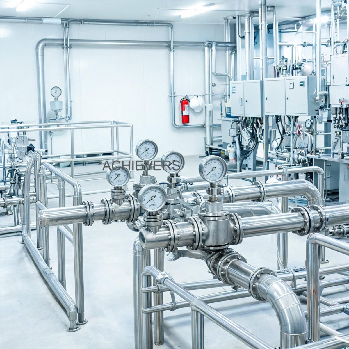
6. Installation & Calibration Best Practices
Achieving the nameplate +/- 0.5% FSD accuracy in field conditions requires strict adherence to fluid dynamics principles. Whether you are evaluating turbine flow meters in India for industrial fuel monitoring, or specifying meters for a North American chemical plant, the foundational principles remain identical. Poor piping geometry will introduce swirl and flow profile distortion, immediately invalidating factory calibration.
Follow this 6-step engineering procedure for optimal installation:
- Verify Straight Run Requirements: Ensure a minimum of 10 Pipe Diameters (10D) of straight, unobstructed piping upstream of the meter, and 5 Pipe Diameters (5D) downstream. Even with built-in straightening vanes, severe upstream disturbances (like partially closed valves or 90-degree elbows) can create non-symmetrical velocity profiles.
- Install Y-Strainers: Because the S.S-316 rotor spins at high angular velocities on a carbon bush, particulate matter can cause catastrophic bearing failure. Always install an upstream Y-strainer (typically 100 to 150 mesh for diesel/oil) to catch debris.
- Align Pipeline Centers: When using flanged connections, ensure gaskets are perfectly centered. A protruding gasket acts as a mini orifice plate, causing localized cavitation and jetting that disrupts rotor velocity.
- Purge Air/Vapor: Turbine meters measure total volume, including entrained gases. In fuel transfer systems, install an upstream air eliminator. Air pockets will cause the turbine to over-spin, leading to significant over-registration of the volume and potential bearing damage from "dry spinning."
- Wire the Signal Correctly: For pulse output sensors, utilize shielded twisted pair wire and ground the shield at the PLC end only to prevent ground loops. Provide exactly 12VDC and verify the pull-up resistor sizing for the NPN open collector circuit.
- Apply Viscosity Correction: If the factory K-factor was generated using water (1 cSt), and the process fluid is heavy oil (e.g., 40 cSt), perform an in-situ calibration test against a known volumetric prover. Adjust the PLC scalar or local index K-factor to match the specific hydrodynamic drag of the oil.
7. Total Cost & Lifecycle Considerations
Procurement heads must evaluate total cost of ownership (TCO) beyond initial capital expenditure. Inline turbine meters represent a middle-ground in flow measurement economics—more affordable than Coriolis mass meters, but requiring more mechanical maintenance than static Electromagnetic meters.
| Technology Option | Relative Cost (USD / Index) | Expected Maintenance Interval | Typical Service Life | Best Process Fit |
| :— | :— | :— | :— | :— |
| Inline Turbine (Threaded) | $ – $$ | 12 – 24 Months (Bearing Check) | 5 – 10 Years | Clean process water, diesel, light oils. |
| Inline Turbine (Flanged Large) | $$ – $$$ | 24 Months | 10+ Years | Bulk fuel transfer, furnace oil, boiler feeds. |
| Insertion Turbine | $ | 12 Months (Sensor clean) | 5 – 8 Years | Large utility lines where high accuracy isn't critical. |
| Positive Displacement | $$$ | 24 – 36 Months | 15+ Years | High viscosity oils, custody transfer, batching. |
| Electromagnetic | $$ – $$$ | > 60 Months (Virtually nil) | 15+ Years | Waste water, acids, conductive slurries. |
FAQ
Q: Can a turbine meter accurately measure high-viscosity fluids like thick crude or heavy furnace oil?
A: Turbine meters are highly accurate for low to medium-viscosity non-acidic liquids. However, once fluid viscosity exceeds roughly 100 cSt, the boundary layer drag on the rotor blades severely impacts linearity and accuracy. For very thick oils, Positive Displacement meters are technically superior.
Q: What is the maximum operating temperature and pressure for these units?
A: The standard units feature a robust S.S-304/316 enclosure allowing maximum working pressures up to 6 MPa (approx. 60 Bar) and fluid/ambient temperature tolerances from -20 °C to 120 °C.
Q: Do I need external power for the local display version?
A: No. The battery-operated models utilize a 3.3V 10AH lithium battery capable of continuous operation for more than 5 years. They also feature a 10-year power-fail protection memory to safeguard cumulative flow data.
Q: How do I integrate the NPN pulse output with my industrial PLC?
A: The pulse output requires a 12VDC power supply. Because it is an NPN open connector type, your PLC input card must source the voltage, or you must install a pull-up resistor to ensure the signal transitions cleanly above 8VDC (High) and below 0.8VDC (Low).
Q: What happens if air or gas passes through the meter with the liquid?
A: The turbine rotor will spin regardless of the fluid phase, meaning air bubbles will be measured as liquid volume, causing over-reading. In high-speed scenarios, large air pockets can cause destructive over-speeding of the carbon bush bearings. Always install an air eliminator upstream.
Q: How often does the K-factor need to be calibrated?
A: For critical applications, verify calibration annually. The K-factor may drift over time due to gradual wear on the hard SS-316 shaft and carbon bush, or if the process fluid's kinematic viscosity changes significantly due to temperature shifts.
Q: Is it safe to install these meters in a vertical pipe run?
A: Yes, but the pipe must be flowing perfectly full at all times. The recommended orientation for vertical runs is upward flow, which ensures the pipe remains packed and prevents cavitation from distorting the velocity profile.
To ensure you select the correct instrumentation for your fluid application, reach out to our engineering team with your specific requirements. Please provide the required flow range, line size, process fluid type, operating temperature, and preferred output signal (Pulse, 4-20mA, or RS485) so we can specify the exact model and K-factor configuration for your facility's long-term success.