
For Indian industrial plants, mining sites, and large-scale construction projects, fuel management is a critical operational pillar. Every minute a fleet vehicle or earthmover spends idling at the refueling bay due to slow fuel delivery translates to direct operational losses. When industrial fueling systems fail to deliver their rated capacity, the root cause is rarely a complete catastrophic failure. More often, it manifests as a degraded flow rate—specifically, dispensing slowly under real load conditions compared to free-flow testing.
Before plant managers and procurement heads authorize the replacement of equipment worth ₹32,000 to ₹86,000, systematic fault isolation is mandatory. Haphazardly swapping out vanes, motors, or meters without proper diagnosis leads to unnecessary downtime and inflated maintenance budgets. This highly detailed guide provides a structured workflow for Diesel Dispensers troubleshooting in India, helping maintenance engineers identify whether the bottleneck lies in hydraulic restrictions, air ingress, electrical supply, or metering components.
1. Quick Reference: How Diesel Dispensers Works
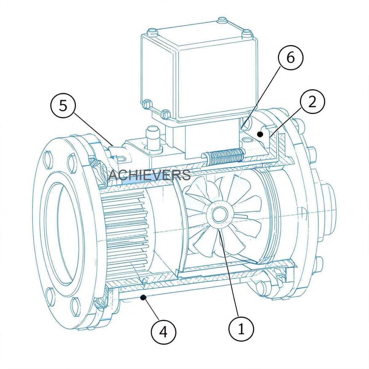
Modern Diesel Dispensers integrate a pumping unit, a metering mechanism, and an electronic or mechanical register into a single, cohesive skid or chassis. The system relies on a positive displacement (PD) rotary vane or gear pump driven by an AC (220V) or DC (12V/24V) motor. As the motor turns the rotor, sliding vanes trap fixed volumes of diesel, drawing it from the storage tank and pushing it toward the metering unit.
Between the pump discharge and the meter inlet lies the most critical hydraulic component: the bypass valve (relief valve). This spring-loaded valve protects the system from overpressure when the delivery nozzle is closed while the pump is still running. If the pressure exceeds the preset limit (typically 1.5 to 2.5 bar), the valve opens, recirculating fuel internally to the suction side.
After passing the pump, the fluid enters the flow meter. The meter utilizes either mechanical positive displacement principles (like nutating disc or oval gear) or turbine mechanics to translate fluid volume into a readable output.
Engineering Formula: Flow Rate under Load
The actual flow rate (Q) of a rotary vane pump inside the dispenser is defined by:
Q = (V_d x N x E_v) – S_l
Where:
- V_d = Displacement volume per revolution
- N = Rotational speed of the motor (RPM)
- E_v = Volumetric efficiency of the pump
- S_l = Slip loss (internal leakage), which increases proportionally with discharge pressure.
Under real refueling load (pushing through a long hose, filter, and automatic nozzle), backpressure increases. If the internal slip (S_l) is high due to worn vanes, or if the motor RPM (N) drops due to voltage fluctuations common in Indian grids, the flow rate severely degrades.
2. Technology Comparison: Metering Units Inside Dispensers
Before proceeding to the troubleshooting matrix, it is vital to understand the metering technology inside your specific Diesel Dispensers, as this dictates flow characteristics and fault symptoms. Most industrial units utilize either Positive Displacement (Oval Gear/Nutating Disc) or Turbine Flow Meters.
Technology Comparison Table
| Parameter | Positive Displacement (PD) Meter | Turbine Flow Meter |
| :— | :— | :— |
| Operating Principle | Traps fluid in fixed volume chambers. | Fluid kinetic energy rotates a bladed rotor. |
| Accuracy | Extremely high (±0.5% or better). | High at steady high flow (±1.0%). |
| Viscosity Handling | Excellent (accuracy improves with thicker fluids). | Poor (calibration shifts if viscosity changes). |
| Pressure Drop | High (creates backpressure on the pump). | Low (allows higher dispensing flow rates). |
| Contamination Tolerance | Very low (gears lock up with hard debris). | Moderate (but bearings can wear out). |
| Cost Implication | Higher initial cost. | Lower initial cost. |
| Ideal Application | Commercial transaction, Legal Metrology compliance. | Internal batching, fast fuel transfer. |
'When to Use This Technology' Decision Matrix
- Use Positive Displacement Meters when: You need high accuracy for inter-departmental billing, fuel auditing, and compliance with strict Legal Metrology standards. Ideal for static, permanent installations where highly filtered fuel is guaranteed.
- Use Turbine Meters when: You require rapid transfer rates with minimal pressure drop. Excellent for mobile bowsers or mining sites where absolute transaction accuracy takes a backseat to fast, bulk liquid movement.
3. General Specifications & Ratings for Indian Operations
To accurately troubleshoot, you must reference the design baseline. A typical heavy-duty industrial diesel dispenser (like the Achievers CE-204 or CE-101 series) operates within the following parameters:
- Standard Flow Rates: 40 LPM to 80 LPM (depending on model and motor wattage).
- Accuracy Rating: ±1% for standard mechanical, ±0.5% for high-precision electronic versions.
- Maximum Working Pressure: 3 Bar (43.5 PSI).
- Temperature Rating: -10°C to +60°C (designed to handle peak Indian summer ambient temperatures).
- Power Configurations: 220V AC (Standard Grid), 12V/24V DC (Mobile/Battery operated).
4. Troubleshooting Matrix: Industrial Diesel Dispenser Low Flow Rate Causes and Fixes
When implementing a diesel dispensers service and repair checklist, refer to this matrix to match symptoms with proven diagnostic actions.
| Symptom | Likely Cause | Diagnosis Steps | Fix |
| :— | :— | :— | :— |
| 1. Slow flow rate under load (but good free flow) | Premature bypass valve opening. | Attach pressure gauge to discharge. Deadhead pump. If pressure is below 1.5 bar, bypass is opening early. | Clean bypass poppet valve; replace fatigued bypass spring. |
| 2. Slow flow & high-pitched whine from pump | Cavitation due to suction restriction. | Check vacuum gauge on suction side. Vacuum > 0.3 bar indicates blockage. | Clean Y-strainer/suction filter. Ensure foot valve is not jammed. |
| 3. Zero flow, motor hums but does not spin | Jammed rotor or locked meter internals. | Disconnect power. Manually turn motor cooling fan. If rigid, internal jam exists. | Dismantle pump head to clear debris, or inspect Positive Displacement Flow Meters for locked gears. |
| 4. Motor trips MCB/thermal overload after 5 mins | Severe voltage drop or excessive backpressure. | Measure line voltage at motor terminals under load. Check for clogged inline filter. | Upsize supply cables. Clean/replace output particulate filters. |
| 5. Erratic reading / skipping numbers | Air ingress in suction line. | Inspect flow visually in a clear calibration jar for micro-bubbles. | Tighten all suction joints; re-tape threads with diesel-resistant PTFE. |
| 6. Continuous small leakage from pump shaft | Worn mechanical seal. | Wipe housing dry, run pump, and observe shaft entry point for weeping. | Replace carbon/ceramic mechanical shaft seal. |
| 7. Display shows dispensing, but no fuel exits nozzle | Sheared motor keyway or broken rotor coupling. | Listen for motor spinning without hydraulic load sound. Open pump head to inspect shaft. | Replace coupling or damaged rotor shaft. |
| 8. Display goes blank when motor starts | Electromagnetic Interference (EMI) or voltage sag. | Check if 12V/24V DC battery voltage drops below 10.5V/21V during cranking. | Charge batteries; ensure separate grounding for electronic board. |
| 9. Flow meter drifts (delivers less than displayed) | Worn internal measuring chambers. | Perform volumetric calibration using Legal Metrology certified 10L/20L conical measure. | Recalibrate meter using the adjustment screw, or replace metering chamber. |
| 10. Dispensing starts fast, then slows to a trickle | Blocked fuel tank breather (vacuum lock in tank). | Open tank filler cap. If a rush of air is heard and flow restores, breather is blocked. | Clean or replace storage tank breather vent. |
5. Step-by-Step Field Diagnosis Procedure
When facing a "slow flow under load" complaint, follow this precise sequence to avoid misdiagnosis.
Tools Required: Multimeter (True RMS), Suction Vacuum Gauge (-1 to 0 Bar), Discharge Pressure Gauge (0 to 5 Bar), Legal Metrology approved 20-liter proving can, stopwatch, standard hand tools.
- Verify the Complaint (The Baseline Test): Dispense exactly 20 liters into a proving can while timing it with a stopwatch. Calculate actual LPM (Liters Per Minute). Compare this against the dispenser's rated specification.
- Check Electrical Supply Under Load: Connect a multimeter to the motor terminals. Trigger the nozzle. For a 220V AC unit, voltage must not drop below 205V. For a 12V DC mobile dispenser, voltage at the motor must not drop below 11.5V. Low voltage reduces motor RPM, directly killing flow rate.
- Inspect the Suction Strainer (The most common fault): Isolate the fuel supply. Open the pump's built-in suction strainer. Indian diesel often contains rust, silica dust, and organic sludge. Clean the mesh with compressed air and re-install.
- Perform a Vacuum Test: Install a vacuum gauge on the suction inlet port. Run the dispenser. Normal vacuum is 0.1 to 0.2 Bar. If the vacuum exceeds 0.3 Bar, the pump is starving. Check the underground tank foot valve, check for collapsed suction hoses, or reduce the suction lift distance.
- Test the Bypass Valve Seating: If suction is perfect but flow is weak, the bypass valve is likely stuck slightly open, recirculating fuel internally. Remove the bypass hex nut, extract the spring and poppet. Look for scoring or a trapped piece of debris preventing full closure.
- Check for Suction Air Leaks (Cavitation vs. Aeration): Run fuel into a clear container. If the diesel looks "milky" and then clears up after resting, air is being sucked into the line from a loose union, a failing shaft seal, or a leaky foot valve. Meters will count this air, leading to massive inaccuracies.
- Evaluate Delivery Side Restrictions: Inspect the automatic shut-off nozzle and the delivery hose. A kinked hose, a clogged automatic nozzle filter screen, or a crushed swivel joint creates immense backpressure, forcing the bypass valve to open prematurely.
- Internal Wear Assessment (Vane Check): If all above checks pass, open the pump faceplate. Inspect the rotary vanes. They should slide freely in their rotor slots. If they are worn down beyond the manufacturer's tolerance or stuck due to varnished diesel, the pump cannot build pressure under load. Replace the vanes.
6. Installation and Setup Errors That Cause Ongoing Problems
Often, diesel dispensers troubleshooting in India reveals that the equipment is perfectly fine, but the installation violates fundamental fluid dynamics principles.
| Installation Error | Resulting Symptom | Engineering Correction |
| :— | :— | :— |
| Excessive Suction Lift (Tank too deep/far) | Severe cavitation, loud pump noise, flow rate reduced by 50%. | Keep vertical suction lift under 3 meters. Use a submersible pusher pump in the tank if lift exceeds 4 meters. |
| Undersized Suction Piping | High friction loss leading to pump starvation. | Suction pipe diameter must equal or exceed the pump inlet diameter. Never use reducers on the suction side. |
| Missing Check Valve / Foot Valve | Pump loses prime between operations; dry runs on startup. | Install a heavy-duty brass foot valve with a strainer at the bottom of the suction drop tube. |
| Improper Electrical Cabling | Motor stalls under load, runs hot, or trips breakers. | Upsize wire gauge, especially for 12V/24V DC units where long cable runs cause severe voltage drops. |
| Using PTFE tape on the suction side incorrectly | Shredded tape gets sucked into the pump, jamming the rotor or bypass valve. | Apply liquid pipe sealant (threadlocker) or leave the first two threads bare when using PTFE tape. |
| No overhead canopy in monsoon/summer | Electronic displays blank out, water ingress in motor terminal box. | Install equipment under a rain canopy. Direct exposure to 45°C sun degrades LCD displays and electronics. |
For high-volume bulk transfer applications where dispensers fall short, consider switching to dedicated high-capacity Fuel Transfer Pumps paired with external batch controllers.
7. Preventive Maintenance to Avoid Recurrence
Routine maintenance is the only defense against the harsh realities of Indian site conditions—dusty mining environments, high monsoon humidity, and occasionally contaminated fuel supplies.
- Weekly: Inspect the automatic nozzle for damage. Ensure the hose is reeled properly and not driven over by trucks. Check for external weeping at all pipe joints.
- Monthly: Open and clean the pump's Y-strainer. If dispensing from a mobile bowser, drain water from the bottom of the diesel tank. Check battery terminal connections on 12V/24V DC mobile diesel dispensers.
- Quarterly Calibration Note: Execute a proving run using a Legal Metrology certified 20L measure. Due to mechanical wear on internal metering components, the K-factor (calibration factor) of electronic displays or the mechanical adjustment screw must be tweaked to maintain ±0.5% accuracy.
- Annually: Replace standard delivery hoses (UV and ozone degrade rubber over time). Inspect and replace motor carbon brushes on DC models before they score the commutator. Replace rotary vanes preventatively if the dispenser runs continuously for multiple shifts.

8. When to Call Service vs. Fix Yourself
Knowing when to escalate an issue saves time and prevents regulatory trouble.
Fix Yourself (In-House Maintenance):
- Cleaning strainers and replacing external filters.
- Replacing damaged delivery hoses, swivels, and dispensing nozzles.
- Resetting electrical trips or replacing fuses.
- Clearing minor debris from the bypass valve.
Call for Manufacturer/Authorized Service:
- Meter Recalibration with Broken Seals: If your dispenser is utilized for commercial sale and sealed under the Legal Metrology Act, breaking the seal to adjust the meter is a legal offense. You must call an authorized certifier.
- Electronic Control Board Failure: If the main PCB has burned tracks due to lightning or power surges, field repairs are rarely reliable.
- Explosion-Proof (Flameproof) Motor Issues: Under PESO (Petroleum and Explosives Safety Organisation) regulations, repairing flameproof motors must be done by certified workshops. Field rewinding voids the safety certification.
*
FAQ
Q: Why does my diesel dispenser pump fast at first, then slow down dramatically after 20 liters?
A: This is a classic symptom of a blocked breather vent on your main storage tank. As fuel is drawn out, a vacuum is created in the tank. Once the vacuum overcomes the pump's suction power, flow drops. Open the fuel cap to see if flow instantly restores.
Q: Can I run a 12V DC mobile dispenser continuously?
A: No. Most DC transfer pumps used in mobile dispensers have a defined duty cycle (typically 30 minutes ON, 30 minutes OFF). Running them continuously will overheat the motor and melt the internal brush assemblies.
Q: The dispenser motor is running, but absolutely no fuel is coming out. What is wrong?
A: First, check if the pump has lost its prime. Ensure the tank isn't empty and the foot valve hasn't failed. If prime is fine, the rotor keyway might have sheared, or the bypass valve is permanently wedged open by debris.
Q: How frequently should we change the internal pump vanes?
A: Under normal Indian industrial conditions with adequately filtered diesel, vanes last between 1,000 to 1,500 hours of actual running time. If you notice a steady, unexplainable drop in flow rate over a few months, it is time to inspect and replace the vanes.
Q: Will installing a finer external filter reduce my dispensing speed?
A: Yes. Moving from a standard 30-micron filter to a fine 10-micron water-absorbing filter increases backpressure. To maintain flow, you may need a higher capacity pump or ensure you change the finer filters much more frequently.
Q: My mechanical display is skipping numbers. Can this be fixed?
A: Number skipping indicates stripped gears inside the mechanical register, often caused by vibration or attempting to reset the meter back to zero while fuel is still flowing. The register gear train usually needs complete replacement.
Q: Why is my pump making a loud rattling sound like marbles inside?
A: That is cavitation. The pump is struggling to pull fuel, causing the liquid to vaporize and collapse violently under pressure. Immediately check for a clogged suction filter, a stuck foot valve, or an excessively long suction line.
To ensure your fleet operations remain uninterrupted, Lumen Instruments provides robust fuel management solutions tailored for harsh Indian site conditions. For inquiries, technical support, or to upgrade your current setup, please contact us with your required flow capacity, application details, and specific site power requirements so we can recommend the perfect dispensing system.