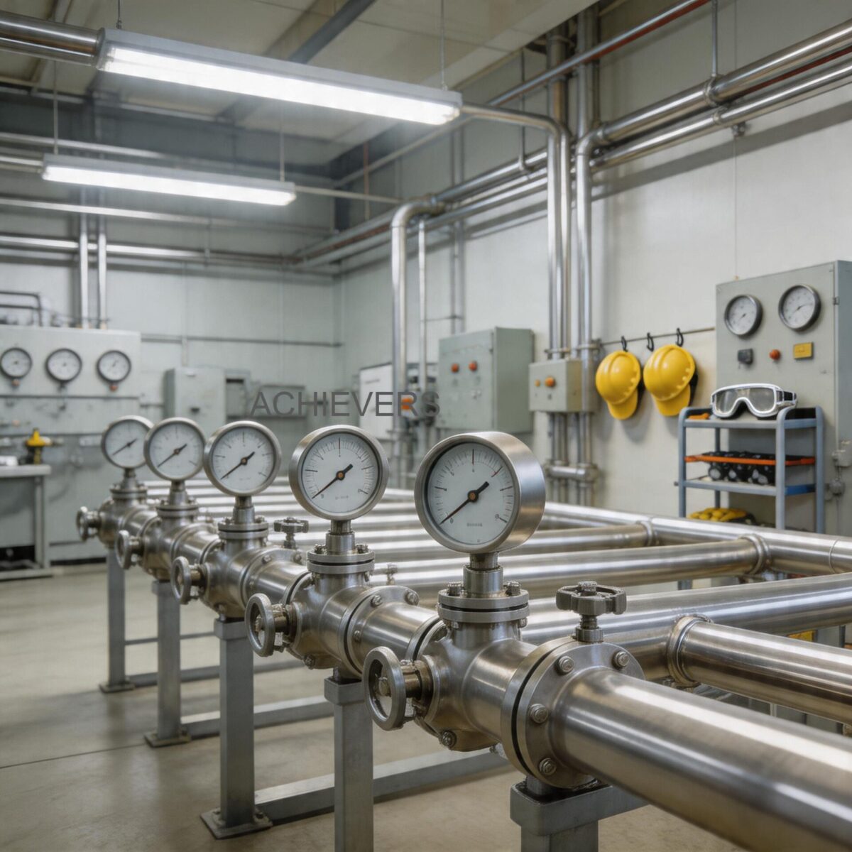
Downtime in industrial process control is measured not just in lost production hours, but in wasted energy, compromised batch quality, and severe financial penalties. When a flow measurement loop fails, plant managers and instrumentation engineers are forced into a reactive stance. Correctly diagnosing instrument faults before resorting to part replacement is critical for maintaining overall equipment effectiveness (OEE) and minimizing maintenance budgets across global operations.
Among the various technologies utilized in modern refineries, chemical plants, and power generation facilities, Vortex Flow Meters are highly regarded for their lack of moving parts, wide turndown ratios, and ability to handle gases, liquids, and steam. However, when these meters exhibit weak outputs, drop to a zero reading during active flow, or display erratic flow rates, the root cause is rarely a catastrophic sensor failure. More often, the issue lies in a complex interplay between fluid dynamics, pipeline installation geometries, Reynolds number limitations, and transmitter configuration.
This comprehensive engineering guide provides a systematic, step-by-step diagnostic workflow for isolating faults in Vortex Flow Meters. By understanding the fundamental physical principles of vortex shedding and examining the specific symptoms presented by the transmitter, industrial buyers and field technicians can quickly isolate root causes, apply targeted corrective actions, and restore reliable measurement integrity without unnecessary hardware replacements.
1. Quick Reference: How Vortex Flow Meters Work
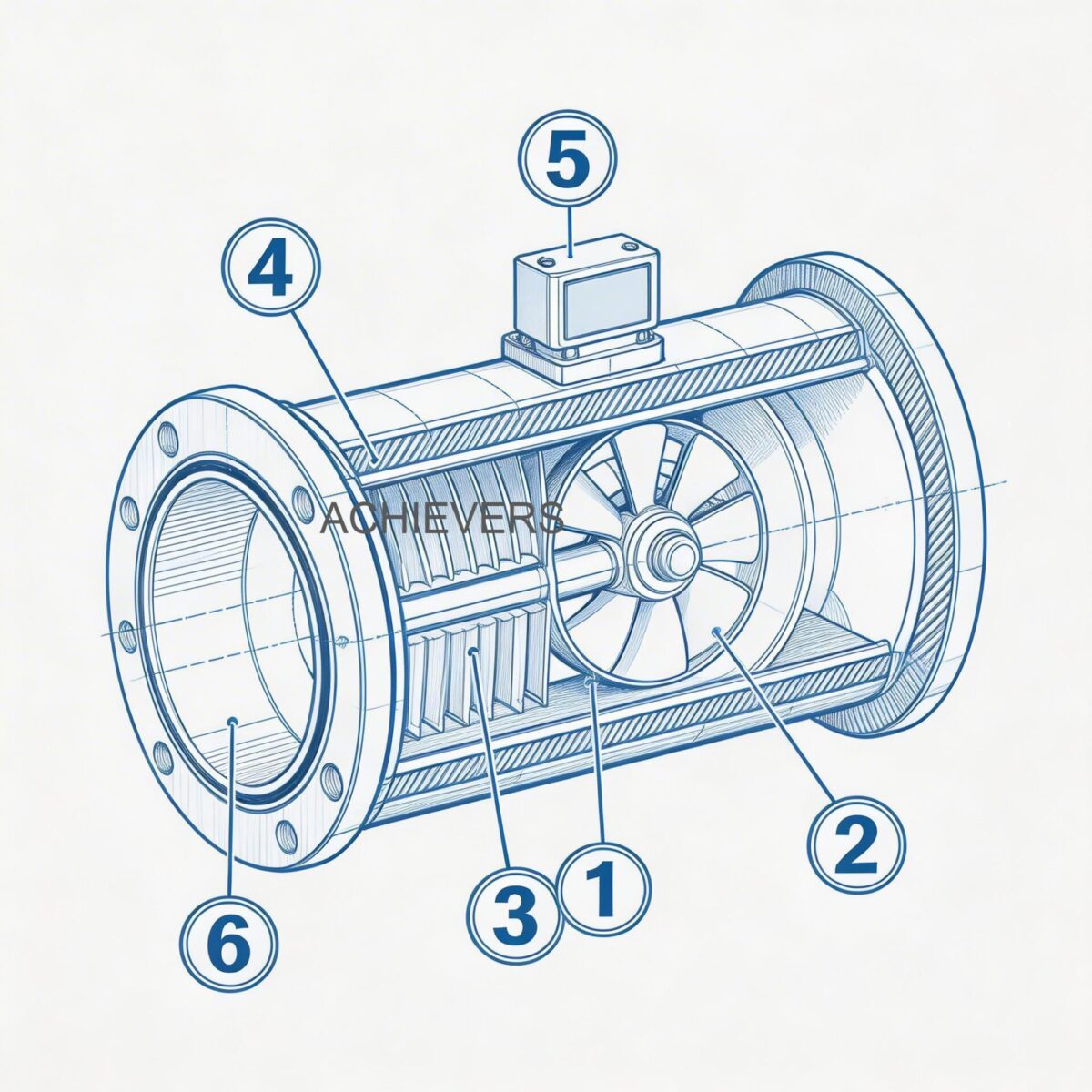
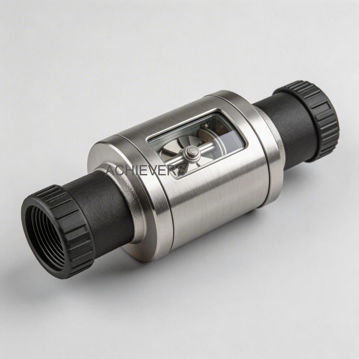
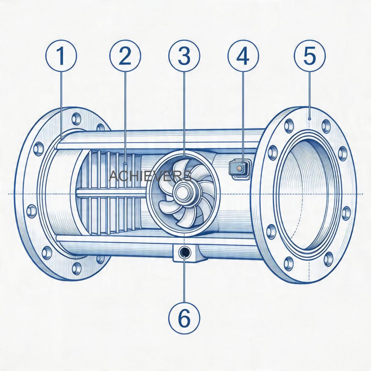
To troubleshoot a complex flow instrument, an engineer must first understand its foundational operating principles. Vortex Flow Meters operate on the Von Karman effect. When a fluid passes a bluff body (an unstreamlined obstacle, often referred to as a shedder bar) placed within the flow stream, alternating low-pressure zones (vortices) are created downstream.
The frequency of these shedding vortices is directly proportional to the fluid's velocity. A piezoelectric sensor or capacitance sensor detects these minute pressure variations and transmits them to the electronics board, which translates the frequency into a volumetric flow rate.
The relationship is defined by the formula:
f = (St * V) / d
Where:
- f is the shedding frequency of the vortices (in Hertz).
- St is the Strouhal number, a dimensionless calibration constant unique to the meter's bluff body design.
- V is the velocity of the fluid.
- d is the width of the bluff body.
For the Strouhal number to remain constant and provide a linear, accurate output, the flow profile must be fully developed, and the fluid's Reynolds number (Re) typically must exceed 10,000. If the flow rate drops and the Reynolds number falls below this threshold, the vortex formation weakens, leading directly to the "low signal" or "zero reading" anomalies commonly reported by operators.
Technical Specifications and Operating Thresholds
When diagnosing a meter, always verify that the process conditions do not exceed the instrument's nameplate ratings. Below are the standard operating specifications derived from advanced field models:
| Specification Parameter | Operating Range / Technical Data |
| — | — |
| Line Size Capability | DN 15 to DN 300mm |
| Temperature Rating | -50 to 350 deg C |
| Maximum Pressure | 20 kg/cm2 |
| Output Signals | 4-20 mA, Pulses, RS 485 Modbus |
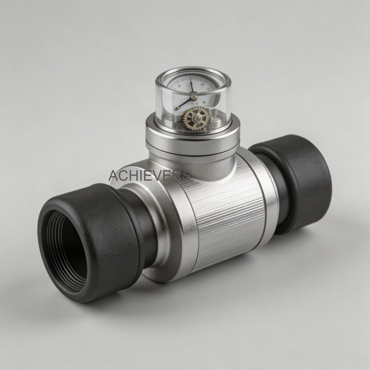
| Signal Compensation | Inbuilt pressure and temperature compensation |
| Power Supply | 24Vdc two-wire |
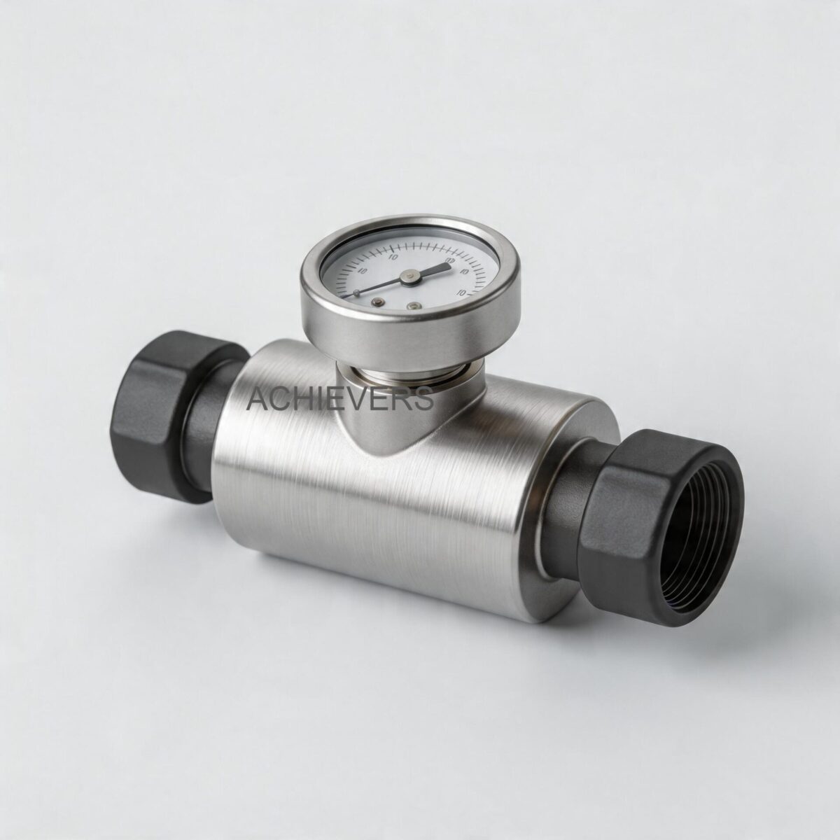
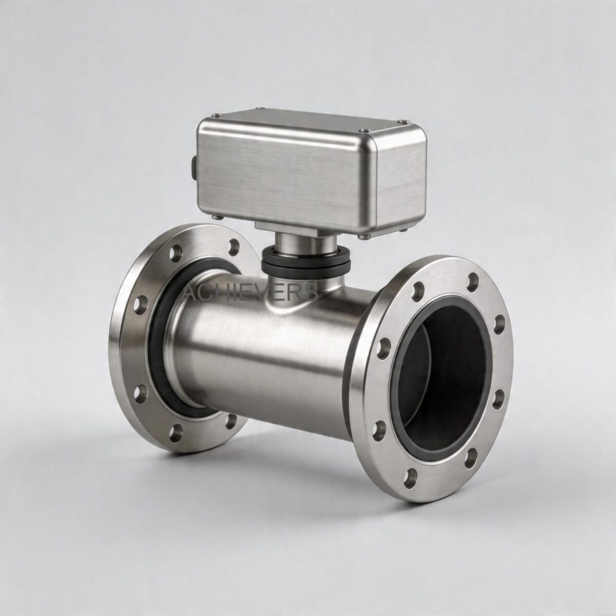
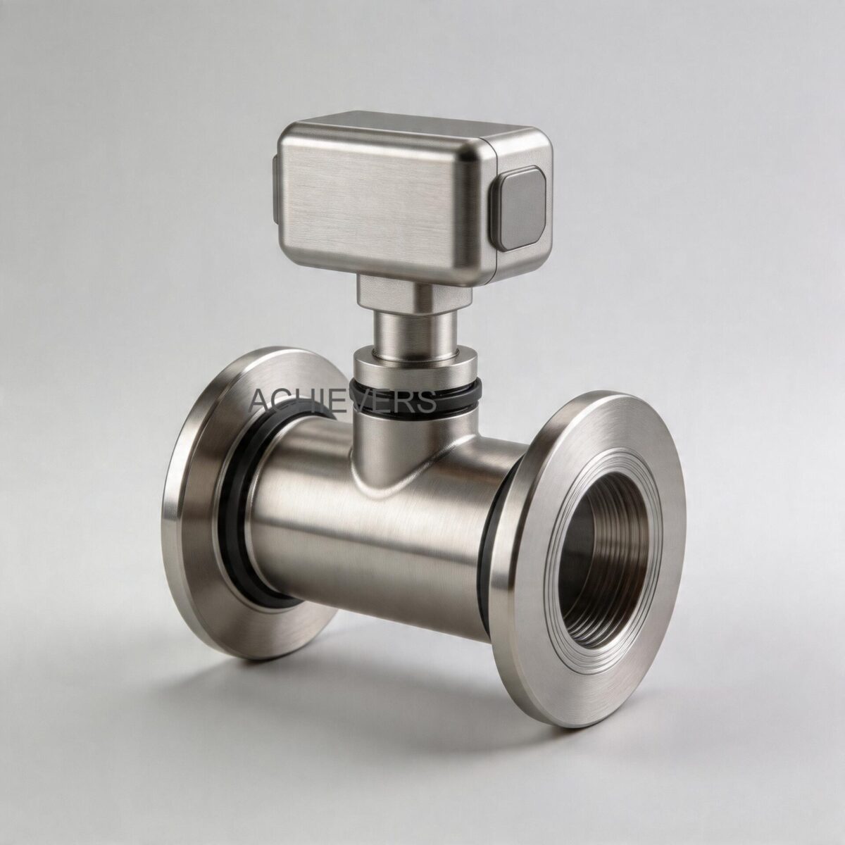
| Mounting Configurations | Flange type / Sandwich (Wafer) type / Clamp On |
2. Technology Comparison Table & Decision Matrix
Instrumentation engineers frequently face the challenge of determining whether Vortex Flow Meters are the correct technology for a failing application, or if the process dynamics demand a different measurement principle. Diagnosing a meter often reveals that it was misapplied from the start.
Cross-Technology Specification Comparison
| Parameter | Vortex Flow Meters | Electromagnetic Flow Meters | Turbine Flow Meters | Positive Displacement |
| — | — | — | — | — |
| Best Fluid Types | Liquids, Gases, Saturated/Superheated Steam | Conductive Liquids, Slurries, Wastewater | Clean, low-viscosity liquids, hydrocarbons | High viscosity oils, fuels, resins |
| Moving Parts | None | None | Rotor / Bearings | Gears / Rotors |
| Pressure Drop | Moderate (due to bluff body) | Zero (unobstructed bore) | Moderate to High | High |
| Reynolds Number Limit | Must be > 10,000 for linear output | Independent of flow profile | Sensitive to viscosity changes | Best at high viscosities |
| Straight Pipe Requirement | High (Typical 20D upstream / 5D downstream) | Moderate (5D upstream / 3D downstream) | High (10D upstream / 5D downstream) | None required |
"When to Use This Technology" Decision Matrix
- Select Vortex Technology when: The application involves utility steam, high-temperature gases (up to 350 deg C), or low-viscosity liquids where moving parts would fail and the fluid is non-conductive. The inbuilt pressure and temperature compensation makes it ideal for saturated steam mass flow calculations.
- Select Electromagnetic Technology when: You are pumping conductive chemical slurries, raw water, or corrosive acids where any pressure drop is unacceptable and the fluid is highly abrasive.
- Select Turbine Technology when: Custody transfer-level accuracy is required for clean hydrocarbons, cryogenic fluids, or aerospace fuels, and you can guarantee heavy filtration upstream to protect the bearings.
- Select Positive Displacement when: You are batching heavy diesel, bunker oil, or thick polymers where high viscosity would severely hinder the accuracy of velocity-based meters.
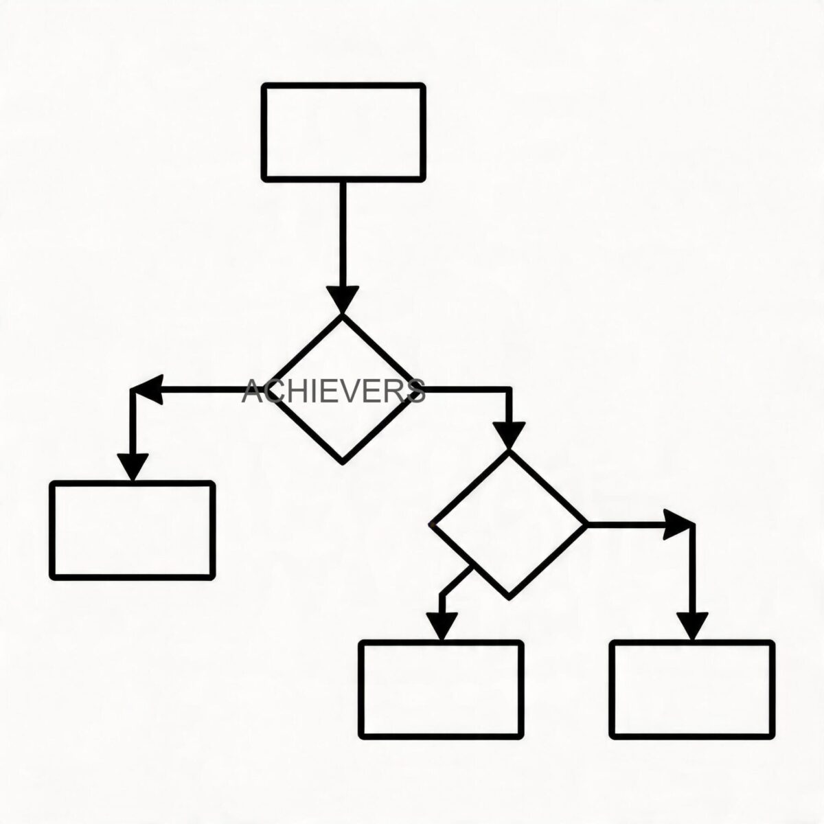
3. Troubleshooting Matrix: Diagnosing Signal Failures
When a Vortex Flow Meter fails in the field, the symptoms generally manifest in the output signal. Use the following diagnostic matrix to rapidly map control room symptoms to physical root causes.
| Symptom / Fault Observation | Likely Root Cause | Field Diagnosis Steps | Engineering Fix / Correction |
| — | — | — | — |
| Zero Flow Reading (While fluid is moving) | Low flow velocity / Low Reynolds Number. | Calculate theoretical velocity. Check if Re < 10,000. Verify low flow cut-off setting in transmitter. | Reduce pipe diameter to increase velocity. Lower the low-flow cut-off threshold (caution: may introduce noise). |
| Erratic / Unstable Flow Rate | Upstream flow disturbances or severe pipe vibration. | Check distance to nearest upstream valve/elbow. Measure pipe vibration frequency with accelerometer. | Re-pipe to ensure 20D straight run, or adjust digital signal processing (DSP) vibration filters in the transmitter. |
| Consistently Low Signal Output | Sensor fouling or incorrect K-factor configuration. | Inspect bluff body for scaling. Cross-reference programmed K-factor with calibration sheet. | Clean shedder bar. Reprogram the exact K-factor matching the specific pipe schedule's internal diameter. |
| Output Drift Over Time | Piezoelectric sensor degradation due to thermal shock. | Check continuity and capacitance of the sensor leads using a multimeter. | Replace sensor module. Implement gradual thermal ramp-up procedures for steam lines. |
| Over-ranging / Pegged at 20mA | Flashing, cavitation, or fluid velocity exceeding meter limits. | Calculate fluid pressure drop. Ensure downstream pressure > vapor pressure of liquid. | Install backpressure valve downstream to prevent cavitation. Resize meter if velocity is truly excessive. |
| Noisy Baseline (Reading flow when pumps are off) | Electrical grounding loop or structural vibration. | Check for continuity between meter body and earth ground. Observe baseline with process completely isolated. | Install dedicated grounding rings. Adjust the noise threshold/trigger level in the amplifier board. |
| 4-20mA Loop Fault / Dead Display | Power supply failure or water ingress in housing. | Measure voltage at terminals (must be 24Vdc). Inspect terminal block for corrosion. | Replace blown fuses, correct wiring polarity, or replace O-rings and use proper cable glands. |
| Modbus Communication Failure | Incorrect baud rate, parity, or termination resistance. | Poll the RS 485 bus with a network analyzer. Check slave ID and wiring topology. | Match baud/parity to DCS. Ensure daisy-chain topology with 120-ohm terminating resistors at ends. |
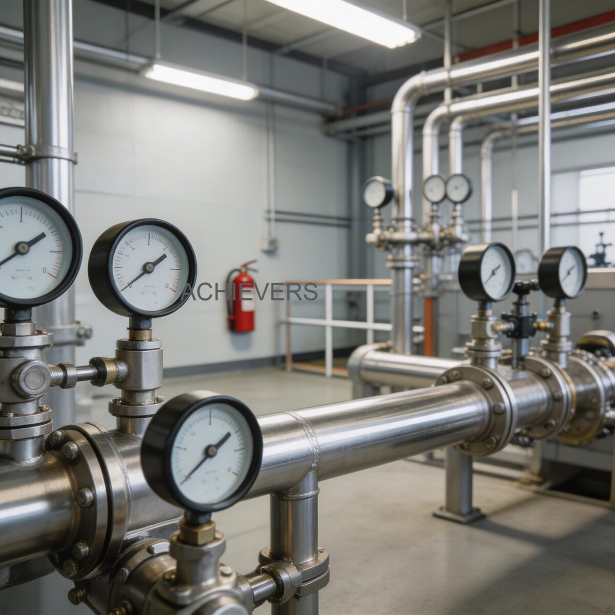
| Excessive Pressure Drop | Meter oversized for the process, creating choke flow. | Install pressure gauges up/downstream. Compare delta-P against manufacturer curves. | Upsize the meter, or evaluate switching to a full-bore electromagnetic meter if the fluid is conductive. |
| Loss of Temp/Press Compensation | Internal RTD or pressure transducer failure. | Navigate to raw sensor data in HART/display menu. Look for Open/Short circuit flags. | Replace the integrated multivariable sensor head. Revert to volumetric flow temporarily if permissible. |
4. Step-by-Step Field Diagnosis Procedure
When replacing parts on a guess, plants waste capital and extend downtime. Instead, follow this mandatory 8-step isolation procedure when dealing with low, zero, or unstable outputs.
Required Tools: High-impedance digital multimeter (DMM), portable oscilloscope, HART communicator or Modbus configuration software, and the meter's original calibration certificate.
- Verify the Process Window: Before touching the instrument, confirm that the fluid is actually flowing. Check upstream pump curves and downstream valve positions. Calculate the estimated Reynolds number. If the flow rate is generating a Reynolds number below 10,000, the meter is functioning correctly by dropping to zero; the physical phenomenon of vortex shedding has simply ceased.
- Check the Power and Loop Integrity: Use the DMM to measure the voltage across the power terminals. For a 24Vdc two-wire system, voltage must not drop below 14-16 Vdc under a full 20mA load. Verify the loop resistance does not exceed the power supply's capacity.
- Analyze the Raw Shedding Frequency: Connect an oscilloscope to the raw sensor output test pins on the amplifier board (if available). You should see a distinct, clean sine wave.
- If the wave is missing during flow, the sensor or bluff body is compromised.
- If the wave is present but the display reads zero, the fault is in the transmitter's microprocessor or analog-to-digital conversion.
- Interrogate the Low Flow Cut-Off (LFC): Connect your HART communicator. Navigate to the signal processing menu. The LFC is designed to mask pipe vibration noise when the line is empty. If the LFC is set too high (e.g., 5% of maximum range), legitimate low-end flow will be forced to read zero.
- Inspect Digital Signal Processing (DSP) and Noise Filters: If the output is unstable or reading flow when valves are closed, check the vibration filtering settings. Modern transmitters allow you to adjust the trigger level. Raise the trigger level slightly until the false flow reading drops to zero, being careful not to tune out actual low-flow signals.
- Verify the K-Factor and Pipe Schedule Match: A common commissioning error is failing to adjust the K-factor for the mating pipe. If the meter was calibrated for Schedule 40 pipe but installed in Schedule 80, the internal diameter difference will alter the flow profile, resulting in constant, low-signal inaccuracies.
- Check Sensor Isolation and Grounding: Vortex meters utilizing piezoelectric crystals are highly susceptible to common-mode electrical noise. Disconnect the sensor leads and check for resistance to the meter body; it should read as an open circuit (infinite resistance). Ensure the meter body is heavily bonded to a true earth ground.
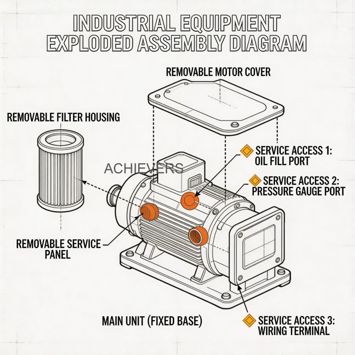
- Physical Inspection for Fouling and Damage: Depressurize the line, lock out the process, and remove the meter. Inspect the shedder bar edges. They must be sharp to generate precise vortices. If the edges are rounded by abrasion or coated with scale/paraffin, shedding will be weak and the output will drift.
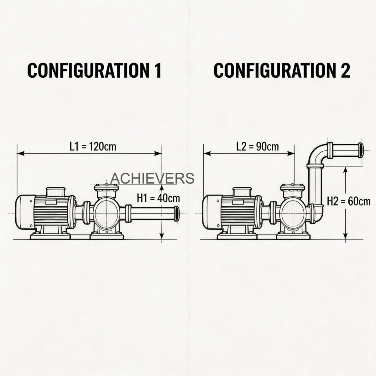
5. Installation and Setup Errors That Cause Ongoing Problems
An improperly installed vortex meter will never achieve its stated accuracy, regardless of how many times the transmitter is replaced. Fluid mechanics dictate that the flow profile must be symmetrical and swirl-free when it strikes the bluff body.
| Installation Error | Hydraulic Symptom | Required Correction |
| — | — | — |
| Inadequate Upstream Straight Pipe | Asymmetrical flow profile causes erratic shedding frequency. | Install minimum 20D straight run upstream, or utilize a high-performance flow conditioner. |
| Gasket Protrusion into Pipe Bore | Creates secondary, false vortices that confuse the sensor. | Re-center flanges. Ensure inner diameter of gaskets matches or slightly exceeds the pipe ID. |
| Control Valve Placed Upstream | Valve throttling introduces extreme noise and jetting velocity profiles. | Always position control valves downstream (minimum 5D) of the flow meter. |
| Meter Installed at High Point in Liquid Line | Entrained air bubbles become trapped, causing signal dropouts. | Relocate meter to a vertical run with upward flow, or a low horizontal section. |
| Poor Thermal Insulation on Steam Lines | Excessive condensation creates two-phase flow (water hammer and wet steam). | Heavily insulate the meter body (leaving transmitter electronics exposed to ambient air) and install steam traps upstream. |
| Misalignment of Wafer (Sandwich) Style Meter | Eccentric mounting shifts the bluff body off the pipe's center axis. | Use specialized alignment rings during installation. Tighten flange bolts in a strict star pattern. |
6. Preventive Maintenance to Avoid Recurrence
While Vortex Flow Meters boast a "no moving parts" design, they are not zero-maintenance devices, especially in harsh applications like saturated steam, dirty gases, or scaling chemical liquids. Implementing a preventive maintenance (PM) schedule will drastically reduce the occurrence of zero-flow dropouts and unstable readings.
Biannual Transmitter Verification:
Every six months, connect a frequency generator to the transmitter in place of the piezoelectric sensor. Sweep the frequency across the meter's operating range (e.g., 10 Hz to 1,000 Hz) to verify that the 4-20mA output scales linearly and exactly matches the DCS readings. This confirms the electronics are sound.
Annual Wet-Side Inspection:
During plant turnarounds, remove the meter and visually inspect the bluff body. In steam applications, boiler carryover can leave mineral deposits on the shedder bar, blunting its edges. Clean the shedder bar with appropriate, non-abrasive solvents. Do not use wire brushes, as scratching the shedding edges will permanently alter the calibration K-factor.
Vibration and Grounding Audits:
Industrial environments change over time. Newly installed pumps or compressors nearby can introduce mechanical resonances that mimic vortex shedding frequencies. Annually audit the piping for severe vibration and ensure that all bonding straps remain uncorroded and securely fastened to the earth ground network.
7. When to Call Service vs. Fix Yourself
Deciding whether to attempt a field repair or dispatch the instrument to a factory service center depends heavily on the root cause isolated during the diagnostic procedure.
Field Fixable:
Issues related to parameter configuration (K-factor, low flow cut-off, damping, 4-20mA scaling) are entirely fixable in the field using a HART communicator. Minor electrical issues, such as replacing a blown varistor, securing loose terminal block connections, or clearing water from the conduit housing, should be handled by site instrumentation technicians. Addressing installation geometry, adding flow conditioners, or correcting grounding loops are also typical field engineering tasks.
Requires Factory Service:
If the physical shedder bar is dented, deeply corroded, or structurally compromised, the meter must be sent to a flow laboratory for replacement and full wet-calibration. Similarly, if the piezoelectric sensor crystal has cracked due to severe thermal shock or water hammer, it requires highly specialized tooling to replace and precisely torque the new sensor assembly. Do not attempt to weld or file the bluff body in the field; altering its geometry by even a fraction of a millimeter invalidates the calibration.
FAQ
Q: Why does my vortex meter read zero when I know there is flow in the pipe?
A: The most common cause is a low fluid velocity resulting in a Reynolds number below 10,000. At this threshold, the fluid does not possess enough kinetic energy to generate vortices. Check the meter sizing; the pipe may be oversized for your flow rate.
Q: Can pipe vibration cause a false flow reading when valves are shut?
A: Yes. Piezoelectric sensors measure microscopic deflections. If the piping vibrates at a frequency similar to typical flow shedding, the transmitter will interpret it as flow. You must increase the low flow cut-off or adjust the digital noise filtering parameters.
Q: Does changing the pipe schedule affect the meter's accuracy?
A: Absolutely. A meter calibrated for Schedule 40 pipe will have a different internal diameter than Schedule 80. This changes the velocity profile and requires the K-factor to be recalculated and re-entered into the transmitter to prevent steady-state accuracy errors.
Q: Why is my meter's 4-20mA output fluctuating wildly but the local display is stable?
A: This usually points to an electrical grounding loop, induced electromagnetic interference (EMI) on the signal cable, or water ingress in the junction box. Ensure the cable shield is grounded at one end only (typically at the DCS cabinet) and not at the meter.
Q: How often should I calibrate a vortex flow meter?
A: Because there are no moving parts to wear out, the physical shedding geometry rarely changes unless subjected to highly abrasive fluids or severe corrosion. Electronics verification should be done annually, but full wet-calibration is typically only required every 3 to 5 years, depending on your local quality regulations (e.g., ISO 9001).
Q: Can a vortex flow meter handle two-phase flow, like wet steam?
A: No vortex meter operates well in continuous two-phase flow. Condensate droplets hitting the sensor cause extreme noise and over-ranging, often referred to as water hammer. Steam lines must be properly insulated and equipped with traps upstream of the meter to ensure the steam remains dry and saturated.
Q: My display is completely dead, but the loop has 24Vdc. What is the issue?
A: If the power supply is verified but the display is blank, the internal power board or LCD module has likely failed due to a voltage spike, lightning strike, or extreme ambient temperatures exceeding the transmitter's rating. The electronics module will need to be replaced.
If you are experiencing persistent flow measurement challenges, our team of engineers is ready to analyze your loop dynamics. Contact us with your application details—including fluid type, operating temperature, maximum pressure, and line size—to discover how properly configured Vortex Flow Meters can optimize your process control and eliminate costly downtime.