
Accurate measurement of fuel and lubricating oils is a critical operational parameter for industrial plants, marine vessels, and power generation facilities globally. Whether monitoring bunker fuel receipts, tracking boiler fuel oil consumption, or managing diesel generator day-tank draw-offs, relying on estimated levels or inaccurate meters results in significant financial losses and inventory discrepancies. Choosing the right Oil Flow Meters requires a deep understanding of fluid dynamics, particularly how high-viscosity hydrocarbons behave under varying temperatures and pressures.
Unlike water or low-viscosity chemicals, industrial oils present unique fluid handling challenges. Kinematic viscosity changes drastically with temperature shifts, pipeline pressure drops can halt gravity-fed systems, and entrained air from storage tank pumps can cause massive volumetric errors. This comprehensive engineering guide breaks down the selection criteria, comparative technologies, and installation specifications required to specify highly accurate, durable flow measurement systems for complex oil applications.
1. What Are Oil Flow Meters and What Do They Do
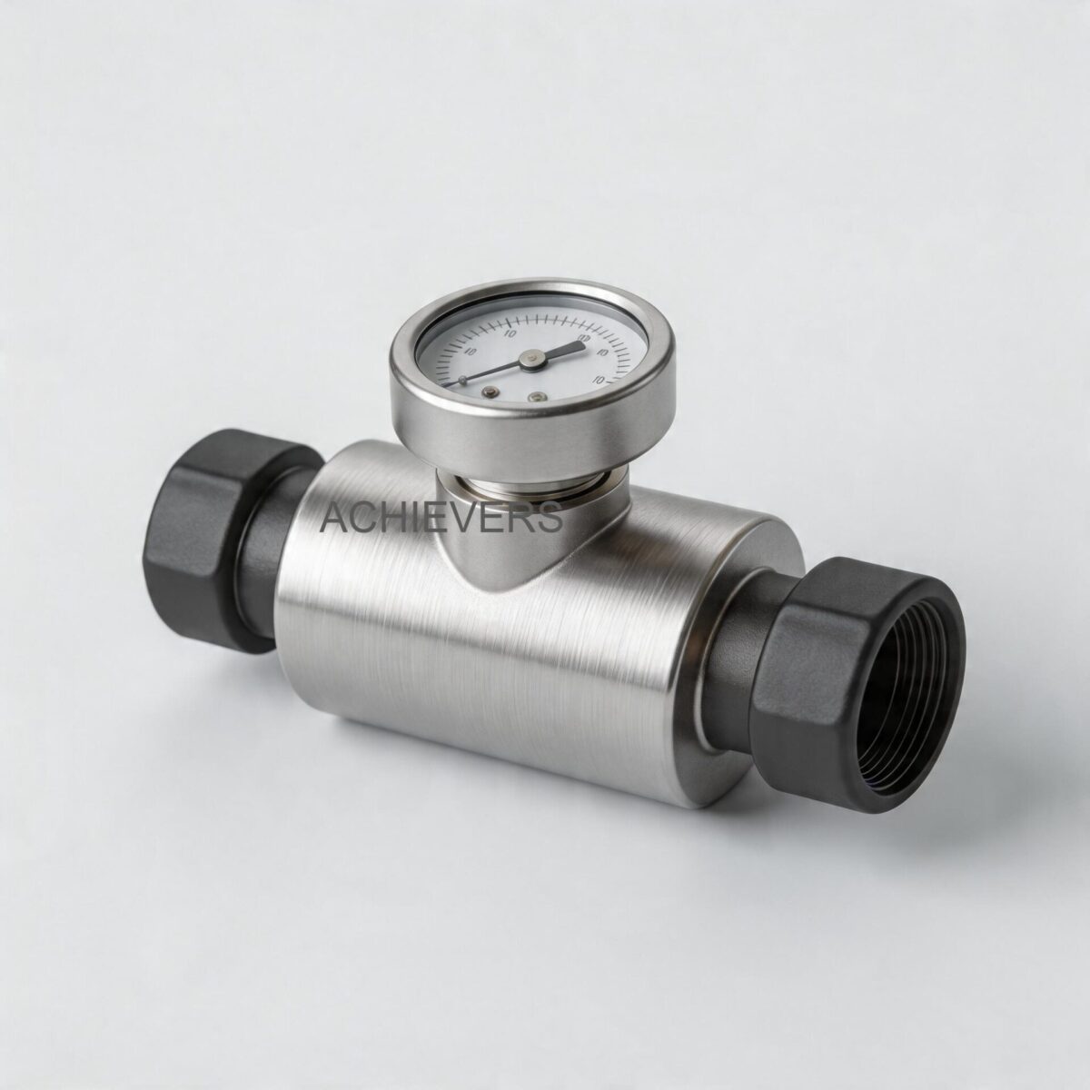
At their core, Oil Flow Meters are precision instrumentation devices designed to continuously quantify the volume or mass of viscous hydrocarbons passing through a pipeline. For boiler, generator, and tank draw-off lines, Positive Displacement (PD) technology—specifically volumetric rotary cylinder or oval gear designs—is the global industry standard.
Positive displacement meters operate by trapping a known volume of fluid between rotating mechanical components (gears or cylinders) and the meter casing. The fluid pressure physically forces these components to rotate. Because the internal measuring chamber has a fixed, exact volume, every rotation represents a highly precise amount of fluid transferred.
Engineering Principle & Calibration Note:
The basic flow equation for a positive displacement meter is:
Flow Rate (Q) = Volume of Chamber (V) x Rotational Frequency (N) + Slip Leakage (q)
Slippage (q) is the minute amount of fluid that passes through the mechanical clearances without causing rotation. In oil applications, higher viscosity actually improves accuracy because the thicker fluid seals these clearances, reducing slippage to near zero. This is why step-less alignment systems in high-quality meters provide exceptional repeatability.
Below are the standard technical specifications for industrial-grade volumetric oil meters:
| Specification | Rating / Parameter | Engineering Notes |
| — | — | — |
| Line Size Capability | 6mm to 150mm (1/4 inch to 6 inch) | Covers small generator lines up to main tank unloading |
| Standard Accuracy | +/- 0.5% of reading | Consistent across wide flow turndown ratios |
| High-Precision Accuracy | +/- 0.2% of reading | Available on request for custody transfer/receipts |
| Repeatability | Better than 0.02% | Critical for batching and precise draw-off records |
| Pressure Drop | Ultra-low (operates under 1 inch head) | Ideal for gravity unloading without external pumps |
| Strainer Requirement | Minimum 100 mesh | Mandatory to protect tight mechanical clearances |
2. Key Selection Criteria for Industrial Buyers
Specifying Oil Flow Meters requires matching the instrument's mechanical and electronic capabilities to the exact pipeline conditions. Plant managers and instrumentation engineers must evaluate the following critical parameters to prevent premature failure or measurement drift.
Viscosity and Fluid Density Profiles
Oils range from light diesel (LDO) to heavy furnace oils. As temperature drops, viscosity increases, which alters the velocity profile of the fluid from turbulent to laminar. Positive displacement meters are immune to these flow profile changes, making them superior for oils, but the meter must be rated for the maximum dynamic viscosity to prevent mechanical shearing or pressure chamber lock-up.
Pressure Drop and Available Head
In many bulk storage facilities, oil is unloaded from tanks via gravity rather than pumps. The meter must impose minimal restriction. Advanced rotary cylinder designs operate effectively under a mere 1-inch head of oil. For gravity emptying, an 80mm size meter is typically recommended, though 50mm can be utilized depending on the required flow rate. For pumped unloading, 50mm or 80mm meters are standard.
Electronics, Telemetry, and Automation Integration
Modern boiler and generator systems require integration into PLC/SCADA networks. While mechanical registers (which require no power and can be rotated to any 90-degree cardinal position) are excellent for remote areas, electronic integration is crucial for automation. Look for modular upgrades like:
- PG 1 (Pulse Generator): Requires a 12-24V DC supply, converting mechanical rotation into a pulse signal via a three-core cable.
- TF 200 (Remote Totalizer & Flow Rate Indicator): Takes the PG1 pulse, totalizes flow, and can output a 4-20 mA analog signal for process control loops.
- BTF 200 (Batching & Totalizer Unit): Features two set-points for dispensing pre-determined quantities, automating tank transfers and blending.
Pipeline Size vs. Flow Rate Optimization
Never size a meter based strictly on the existing pipeline diameter; size it based on the actual minimum and maximum flow rates. If the fuel consumption rate of a boiler is very low but the pipe size is large, you must use reducers and install a smaller meter (e.g., 15mm, 20mm, or 25mm) to maintain measurement accuracy within the meter's linear operating range.
Mechanical Contamination and Filtration
Oil lines invariably carry scale, rust, and particulate matter. Because PD meters rely on exceptionally tight machining tolerances to maintain accuracy, particulate contamination will stall the rotors. A dedicated strainer of at least 100 mesh must be installed immediately upstream of the meter.
Entrained Air Elimination
When unloading petroleum products via pumps, air is frequently drawn into the fluid stream as tanks empty. Volumetric meters measure total volume—fluid and air combined. Without an air release framework installed upstream, entrained air will cause severe over-registering and false fuel receipt records.
3. Technology Comparison & Decision Matrix
No single flow measurement technology fits every application. While positive displacement is the undisputed champion for viscous oils, it is essential to understand how it compares against other common instrumentation like Turbine Flow Meters or Coriolis meters.
Technology Comparison Table
| Parameter | Positive Displacement (Oval/Rotary) | Turbine Meters | Electromagnetic Meters | Vortex Meters |
| — | — | — | — | — |
| Best For | High-viscosity oils, diesel, furnace oil | Low-viscosity, clean fluids, water | Conductive fluids (Water/Slurries) | Steam, gases, low-viscosity liquids |
| Viscosity Tolerance | Excellent (Accuracy improves with viscosity) | Poor (High viscosity severely degrades accuracy) | N/A (Cannot measure non-conductive oils) | Poor (Requires high Reynolds numbers) |
| Straight Run Requirement | Zero (0D upstream / 0D downstream) | High (10D upstream / 5D downstream) | Moderate (5D upstream / 3D downstream) | High (10D-20D upstream) |
| Pressure Drop | Very Low (Suitable for gravity feeds) | Moderate to High | Zero (Full bore) | Moderate (Bluff body restricts flow) |
| Power Requirement | None (Mechanical register options) | Loop-powered or external | High (Requires active magnetic field) | Loop-powered |
"When to Use This Technology" Decision Matrix
- Choose Positive Displacement Meters when: You are measuring diesel, furnace oil, or lubricants; the fluid is non-conductive; pipeline straight-runs are unavailable; or the system operates on a low-pressure gravity feed.
- Choose Turbine Flow Meters when: You are measuring clean, low-viscosity fluids (like light solvents or water) at high velocities where pressure drop is not a critical constraint.
- Choose Electromagnetic Flow Meters when: You are measuring water or highly conductive water-based slurries. (Note: Mag meters will not work on hydrocarbons or oils as they lack electrical conductivity).
- Choose Vortex Meters when: You are measuring utility steam going to the boiler, rather than the fuel oil feeding the boiler burners.
4. Common Mistakes Buyers Make When Choosing
Procurement and engineering teams often face systemic measurement failures due to easily avoidable specification errors. Here are the most common pitfalls:
- Sizing the Meter by Pipe Diameter Instead of Flow Rate: Installing an 80mm meter on an 80mm line that only sees 10 liters per minute of flow will result in massive under-registration. Always size the meter based on the dynamic flow rate, using pipe reducers if necessary.
- Neglecting the Upstream Strainer: Installing a high-precision rotary cylinder meter without a 100-mesh strainer guarantees premature failure. Weld slag or tank rust will physically jam the rotors, causing production downtime and destroying the internal chamber.
- Ignoring Entrained Air in Pumped Lines: Failing to install an air release valve upstream of the meter during tank unloading means the facility ends up paying for "metered" air. This is a primary cause of inventory disputes between fuel suppliers and plant managers.
- Overlooking Pressure Drop in Gravity Systems: Specifying a meter with a complex internal flow path (like a Coriolis or Turbine) on a gravity-fed tank draw-off line will restrict flow to the point where the line barely trickles. Rotary cylinder PD meters are required because they operate on as little as 1-inch of liquid head.
- Failing to Plan for Return Flow in Generators: Diesel generators often pull more fuel than they consume, returning hot fuel back to the day tank. If only one meter is installed on the supply line, the consumption data will be wildly inaccurate. Differential metering (one meter on supply, one on return) is required.
5. Standard Installation Procedure for Oil Flow Meters
To guarantee the +/- 0.5% standard accuracy and ensure a long operational life, proper mechanical installation is strictly required. Follow these engineering steps for commissioning:
- Flush the Pipeline: Before the meter and strainer are fitted, the entire pipeline network must be flushed thoroughly at high velocity to remove construction debris, weld slag, and scale.
- Install a Bypass Loop: To simplify subsequent servicing and calibration without halting plant operations, install a bypass line with appropriate isolation valves around the meter station.
- Fit the Strainer: Install a strainer with a minimum of 100-mesh rating immediately upstream of the flow meter. Ensure the strainer basket is accessible for routine blowdowns.
- Install Air Elimination: If the oil is being unloaded via a pump (especially from mobile delivery tankers), install a mechanical air release mechanism at the highest point upstream of the meter to vent entrained gases.
- Align the Measuring Chamber: Mount the meter in the pipeline ensuring that the volumetric rotary cylinder or oval gears are oriented correctly according to the manufacturer's plane specifications. (Note: Lumen volumetric cylinder designs maintain accuracy irrespective of the mounting plane, but the register dial should be rotated and secured in one of the four cardinal positions for easy reading).
- Terminate Electronic Outputs: If utilizing a pulse generator (PG 1), route the three-core cable to the remote totalizer (TF 200) or batch controller (BTF 200). Ensure the 12 to 24-volt control supply is isolated from high-voltage AC lines to prevent signal interference.
6. Enquiry Specification Checklist
When requesting a quotation or designing a system layout, provide your flow measurement supplier with this exact data to ensure perfect meter matching:
- Fluid Composition: Exact type of oil (Diesel, HFO, LDO, Lubricants, Vegetable Oil).
- Kinematic Viscosity: Expected viscosity range at operating temperatures (in cSt or mPa·s).
- Flow Rates: Absolute minimum, normal operating, and maximum peak flow rates (LPM or m³/hr).
- Operating Pressure: Maximum line pressure and available head (specify if gravity fed or pumped).
- Operating Temperature: Minimum, normal, and peak fluid temperatures.
- Line Size and Connections: Pipe internal diameter and preferred flange standards (e.g., DIN ND10, ANSI, or screwed ends for smaller 15mm-25mm sizes).
- Accuracy Class: Standard (+/- 0.5%) or high-precision (+/- 0.2%) requirements.
- Output Signals Required: Mechanical display only, Pulse (PG1), 4-20mA analog, or Batch Control integration.
FAQ
Q: Do positive displacement oil flow meters require straight pipe runs for accurate measurement?
A: No. Unlike turbine or vortex meters, positive displacement meters mechanically trap and measure fluid volume. They are immune to swirl and velocity profile distortions, meaning zero straight pipe diameters are required upstream or downstream.
Q: How does fluid temperature affect the accuracy of the meter?
A: Temperature changes the fluid's viscosity. While PD meters handle high viscosity beautifully, extreme temperature shifts can cause thermal expansion of the mechanical internals or alter the fluid volume. For precision custody transfer, automatic temperature compensation electronics may be required.
Q: Can these meters operate without an external power supply?
A: Yes. When equipped with standard mechanical registers and totalizers, the fluid's own kinetic energy drives the meter and the display. This makes them perfectly suited for remote storage tanks or hazardous zones where running power cables is dangerous or impractical.
Q: What maintenance is required for a volumetric oil meter?
A: Maintenance is exceptionally low due to the single moving part exposed to the metered liquid via magnetic coupling. The primary maintenance task is regularly cleaning the upstream 100-mesh strainer and periodically verifying calibration accuracy.
Q: Why is my meter registering flow when the generator is off but the pump is running?
A: This is almost always caused by entrained air in the system or an incorrectly plumbed return line. The meter will measure air volume just as it measures liquid. Ensure an air release system is installed upstream.
Q: Can I use a single meter to track my diesel generator's fuel consumption?
A: Usually, no. Most large generators use a recirculating fuel system where fuel is pumped to the injectors, and the unburned hot fuel is returned to the day tank. To measure true consumption, you must use a differential metering setup: one meter on the supply line minus the readings from a second meter on the return line.
Q: What happens if I install the meter without a bypass line?
A: If the meter's internal chamber locks up due to a bypassed or ruptured strainer, flow will completely stop. Without a bypass line, you will have to shut down the boiler or generator entirely to remove and repair the meter.
To ensure you select the optimally sized, chemically compatible, and correctly calibrated oil flow meter for your specific boiler, generator, or tank infrastructure, speak with our instrumentation engineers today. Please provide your expected fluid viscosity, minimum/maximum flow rates, and available system pressure to receive a precise technical recommendation and quotation.