
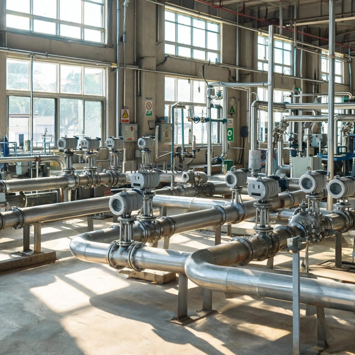
In heavy industries across India—from pharmaceutical manufacturing in Baddi to petrochemical refineries in Jamnagar—utility management dictates profitability. Steam and compressed air are among the most expensive utilities to generate. Accurately measuring these gases is critical for energy audits, boiler efficiency calculations, and departmental billing. When unplanned failures occur on utility lines, the cost is measured not just in replacement parts, but in lakhs of rupees lost to process downtime and wasted energy. Implementing a rigorous preventive maintenance schedule is the only engineering defense against instrument drift and sudden failure.
Unlike moving-part technologies, Vortex Flow Meters operate on the von Kármán effect, relying on a static bluff body to generate alternating vortices. While they are exceptionally robust, they are not completely immune to degradation. In Indian plant conditions, severe pipeline vibration, wet steam carryover, scaling from hard water treatment failures, and electrical fluctuations can degrade signal quality. A scheduled maintenance approach ensures that your Vortex Flow Meters remain highly accurate, stable, and responsive, preventing the slow calibration drift that often goes unnoticed until a major mass-balance discrepancy occurs.
By understanding the underlying physics, adhering to pressure and temperature ratings, and performing routine sensor diagnostics, plant instrumentation engineers can extend the service life of their Vortex Flow Meters well beyond a decade.
Engineering Decision Matrix: When to Use This Technology
Before committing to a maintenance regimen, it is vital to ensure the flow meter is correctly applied. Misapplication is the leading cause of premature failure.
- Ideal Applications: Saturated and superheated steam (up to 350°C), compressed air, nitrogen, boiler feed water, and low-viscosity petrochemicals. Excellent for lines where pressure drop must be minimized and moving parts are a liability.
- Poor Applications: Highly viscous fluids (heavy fuel oil, molasses) where the Reynolds number drops below 10,000, preventing consistent vortex shedding. Extremely abrasive slurries that erode the bluff body. In highly abrasive, conductive liquid applications, Electromagnetic Flow Meters are the standard choice.
- Pipeline Prerequisites: Requires strict adherence to straight pipe runs (typically 20D upstream, 5D downstream) to ensure a fully developed, symmetrical flow profile.
Technology Comparison Table: Steam and Gas Measurement
Selecting the right technology for utility lines involves balancing accuracy, pressure drop, and maintenance requirements.
| Parameter | Vortex Meter | Differential Pressure (Orifice) | Turbine Flow Meter |
| — | — | — | — |
| Primary Use Case | Steam, Gases, Clean Liquids | High-temp steam, large lines | Clean gases, high-accuracy liquids |
| Moving Parts | None (Static bluff body) | None | Yes (Rotor and bearings) |
| Turndown Ratio | 20:1 to 30:1 | Typically 3:1 to 4:1 | 10:1 to 15:1 |
| Pressure Drop | Low to Medium | High (Permanent pressure loss) | Medium |
| Wear Characteristics | Sensor fatigue, bluff erosion | Orifice edge dulling (drastic accuracy drop) | Bearing wear, blade damage |
| Maintenance Need | Low (Periodic cleaning) | High (Impulse line purging, zeroing) | High (Bearing replacement, calibration) |
(Note: For highly critical custody transfer of clean liquids with low viscosity, Turbine Flow Meters often provide superior accuracy, provided robust filtration is in place.)
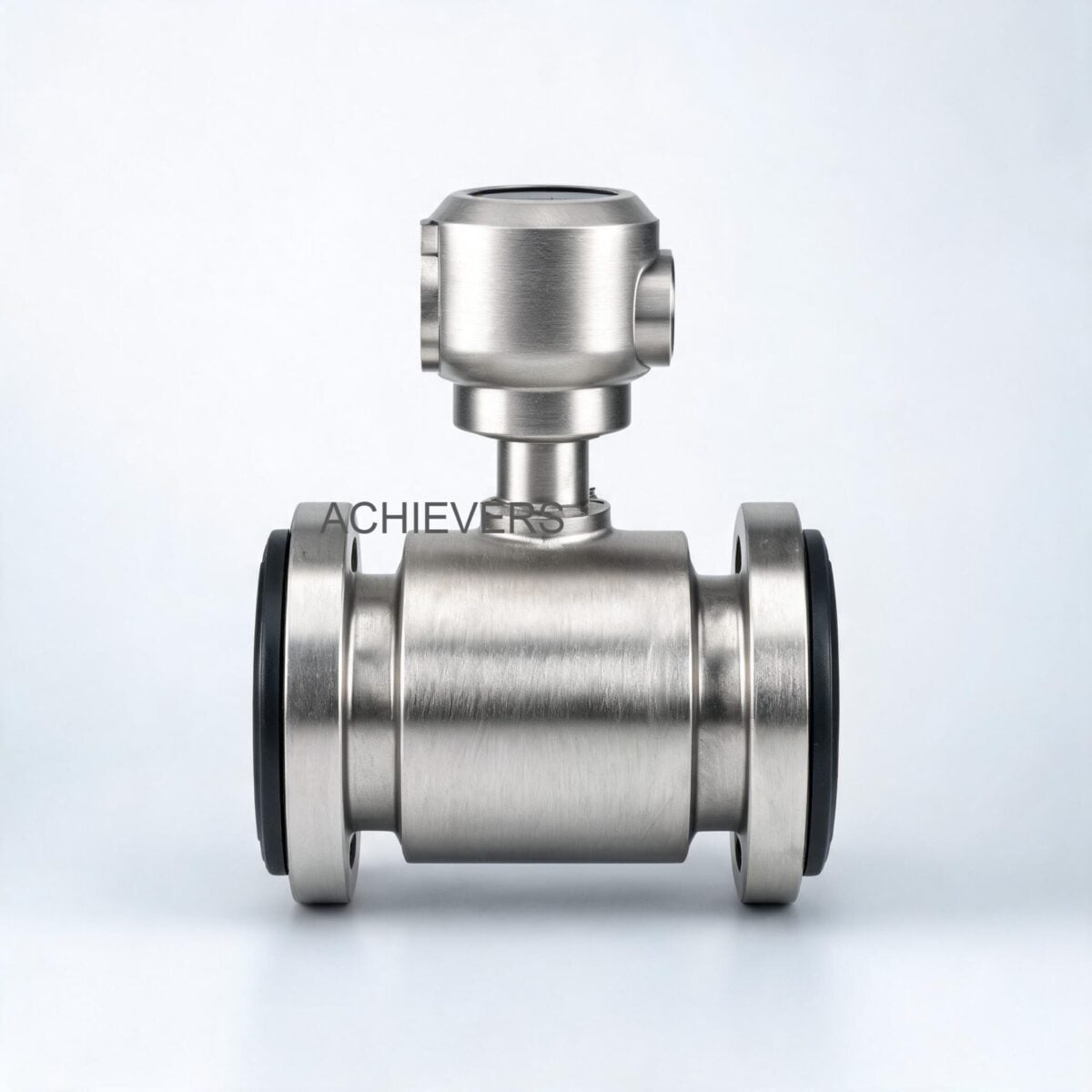
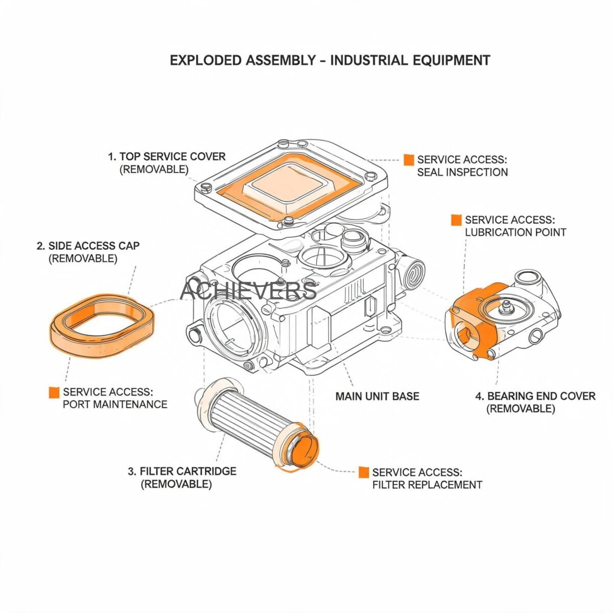
1. Product Overview and Critical Wear Components
The operational principle of a vortex meter relies on the Strouhal equation:
f = (St * V) / d
Where:
- f = Frequency of vortex shedding (measured in Hz by the sensor)
- St = Strouhal number (a dimensionless constant, typically ~0.2 over a wide range of Reynolds numbers)
- V = Flow velocity
- d = Width of the bluff body
Because the frequency is directly proportional to velocity, the meter calculates volumetric flow. With inbuilt pressure and temperature compensation, it instantly calculates mass flow for steam and compressed air. While the bluff body itself does not move, the piezoelectric sensor behind it undergoes continuous mechanical stress. Furthermore, the accuracy relies on the sharp edges of the bluff body; if these edges are rounded by wet steam erosion or coated by pipe scale, the Strouhal number shifts, causing calibration drift.
Technical Specifications Summary
The maintenance guidelines in this article are specifically calibrated for meters built to the following Lumen Instruments technical specifications:
| Specification Parameter | Rated Value / Detail |
| — | — |
| Line Size Range | DN 15 to DN 300mm |
| Temperature Rating | -50°C to 350°C |
| Maximum Pressure | 20 kg/cm2 |
| Output Signals | 4-20 mA, Pulses, RS 485 Modbus |
| Mass Flow Compensation | Inbuilt for Pressure and Temperature |
| Power Supply | 24Vdc two-wire |
| Mounting Configurations | Flange type / Sandwich (Wafer) type / Clamp On |
2. Preventive Maintenance Schedule
To guarantee stability in Indian industrial utilities—where line pressure fluctuates and boiler water chemistry can occasionally fail—adhere to this schedule.
| Task | Frequency | Responsible | Est. Time | Notes |
| — | — | — | — | — |
| Visual Display Check | Weekly | Field Operator | 5 mins | Verify flow readings, check for error codes or erratic bouncing in flow rate. |
| Enclosure Inspection | Monthly | Instrument Tech | 10 mins | Ensure IP65/67 seals are intact. Check cable glands for moisture ingress (crucial during Indian monsoons). |
| Vibration & Noise Check | Monthly | Mechanical Tech | 15 mins | Check pipe supports and lagging. Excessive pipeline vibration induces false vortex readings. |
| Zero Verification | Quarterly | Instrument Tech | 20 mins | Close upstream/downstream valves. Ensure 4-20mA output drops to exactly 4.00mA at zero flow. |
| Grounding Integrity | Quarterly | Electrical Tech | 15 mins | Test earth loop resistance. Poor grounding causes RS485 communication failures and erratic pulses. |
| Filter/Strainer Blowdown | Quarterly | Mechanical Tech | 30 mins | Purge upstream Y-strainers on steam lines to prevent weld slag or scale from impacting the bluff body. |
| Analog Output Calibration | Bi-Annually | Instrument Eng. | 45 mins | Inject frequency signal into transmitter, verify 4-20mA loop accuracy against plant DCS/SCADA. |
| Bluff Body Inspection | Annually | Plant Maintenance | 2 hours | Depressurize line, remove meter, inspect bluff body edges for erosion, pitting, or scaling. |
| Gasket/Seal Replacement | Annually | Plant Maintenance | 1 hour | Replace flange/sandwich mounting gaskets to prevent high-pressure (20 kg/cm2) leaks. |
| Complete Recalibration | Every 2 Years | Metrology Lab | 3-5 days | Send to NABL-accredited flow lab for wet/gas calibration to maintain ISO 9001 compliance. |
3. Step-by-Step Procedures for Key Tasks
Proper execution of maintenance tasks prevents accidental damage to the delicate piezoelectric sensors.
Procedure 1: Upstream Strainer and Pipeline Purging
Scale and debris are lethal to flow profiling. This procedure must be executed during planned shutdowns, especially on aging mild-steel steam lines.
- Coordinate with Boiler House: Ensure the steam or compressed air line is bypassed or isolated. Verify zero pressure via local gauges.
- Lockout/Tagout (LOTO): Apply LOTO procedures to both upstream and downstream isolation valves.
- Allow Cooling: On steam lines rated up to 350°C, allow the pipe and surrounding lagging to cool below 50°C to prevent thermal burns.
- Locate Upstream Strainer: Find the Y-strainer installed upstream of the required straight pipe run.
- Remove Blowoff Valve/Cap: Slowly crack the blowdown valve to ensure no residual trapped pressure exists, then remove the cap.
- Extract and Clean the Mesh: Pull the stainless steel mesh filter. Use a wire brush and industrial solvent to remove hard water scale, rust, and pipe dope.
- Inspect for Damage: Check the mesh for tears. A torn mesh will allow pipe scale to travel at high velocity and strike the bluff body, potentially cracking the piezoelectric crystal.
- Reassemble and Test: Reinstall the mesh, fit a new gasket to the strainer cap, tighten to torque specs, and slowly open the upstream valve to check for leaks.
Procedure 2: Piezoelectric Sensor and Bluff Body Inspection
Erosion of the bluff body alters the Strouhal number, directly degrading the ±1.0% accuracy specification.
- Isolate and Depressurize: Safely isolate the flow meter and drain all residual fluid or vent all gas.
- Disconnect Power: Isolate the 24Vdc two-wire power supply at the junction box or DCS panel.
- Dismount the Meter: For Flange or Sandwich type meters, remove the flange bolts evenly. Support the meter weight (heavy sizes up to DN 300mm require chain blocks).
- Visual Inspection of Bluff Body: Use a high-lumen flashlight to inspect the shedder bar. The leading edges must be sharp, not rounded or pitted.
- Clean the Sensor Area: If boiler chemical carryover has left a calcium/magnesium scale on the body, clean it carefully using a soft brush and a mild acidic descaler.
- Do Not Use Abrasives: Never use grinding wheels, files, or hard wire brushes on the bluff body. Altering its geometry destroys the factory calibration.
- Inspect Piezo Assembly: Check the external housing of the piezoelectric sensor for hair-line cracks or steam leaks.
- Reinstall with New Gaskets: Remount the flow meter using new, correctly sized spiral-wound gaskets. Ensure gaskets do not protrude into the inner diameter of the pipe, as this will generate false vortices.
4. On-Site Spare Parts to Stock
Procurement heads should maintain an inventory of critical spares to prevent a ₹500 gasket failure from halting a ₹5,00,000 daily production run.
| Part Description | Type / Application | Recommended Qty | When to Replace |
| — | — | — | — |
| Spiral Wound Gaskets | High Temp (-50 to 350°C) | 4 sets per meter | Every removal / Annually |
| Piezoelectric Sensor | Sensing Element | 1 per 5 meters | If flow reads zero despite actual flow |
| Transmitter Board | Electronics (4-20mA/Pulse) | 1 unit | Lightning strike, power surge |
| O-Rings / Seals | Enclosure weatherproofing | 2 sets | Whenever enclosure is opened |
| Desiccant Packets | Internal moisture control | 10 packets | Quarterly, post-monsoon |
5. Diagnosing Maintenance-Related Failures
When a meter fails, operators often blame the instrument. In most cases, the failure is a symptom of neglected pipeline maintenance.
| Failure Symptom | Missed Maintenance Task | Corrective Action |
| — | — | — |
| Flow reading at zero actual flow | Pipe vibration dampening check | Install robust pipe supports; adjust low-flow cutoff threshold in electronics. |
| Erratic or jumping output | Grounding integrity check | Repair earth pit; ensure 24Vdc shield wire is grounded at one end only. |
| Consistently low reading | Filter/Strainer blowdown | Clean upstream strainer; inspect bluff body for heavy scale buildup reducing pipe ID. |
| No 4-20mA output signal | Enclosure seal inspection | Check for water ingress in terminal block; replace blown 24Vdc fuse or transmitter board. |
| Communication loss (RS485) | Cable gland tightening | Check Modbus terminals for corrosion; verify cable shielding against electrical noise. |
| Unexplained pressure drop | Pipeline blowdown / purging | Remove blockage from upstream pipe; ensure line size matches DN rating correctly. |
6. Extending Service Life in Indian Conditions
Indian industrial environments present unique challenges that Western operating manuals rarely address. To ensure longevity from your flow measurement investments, implement these site-specific adaptations:
- Combating Monsoon Humidity: High humidity in coastal areas (Mumbai, Chennai) or during the monsoon leads to condensation inside the transmitter housing. Always ensure the meter cover is tightened fully. Route the electrical conduit with a "drip loop" so water runs away from the cable glands, not into them.
- Managing High Ambient Heat: While the meter is rated for process temperatures up to 350°C, the ambient temperature around the transmitter electronics should not exceed 65°C. In foundries or open-sun installations in Rajasthan or Gujarat, install a simple metallic sun-shade over the transmitter head to prevent LCD degradation and PCB thermal fatigue.
- Electrical Surges and Brownouts: Grid fluctuations are common. Always power the 24Vdc loop using a high-quality Switch Mode Power Supply (SMPS) with built-in surge protection. If utilizing the RS485 Modbus output, install data-line surge protectors to shield the transmitter from lightning-induced transients.
- Wet Steam and IBR Compliance: In sugar and paper mills, boiler load swings often cause water carryover (wet steam). Water droplets traveling at 30 m/s act like sandblasting media against the bluff body. Ensure thermodynamic steam traps and moisture separators are installed upstream of the vortex meter, and ensure all installations comply with Indian Boiler Regulations (IBR).
- Vibration in Aging Infrastructure: Older Indian plants often suffer from poor pipe-racking. Vortex meters are highly sensitive to pipe vibration, which mimics vortex frequencies. Install the meter as close to a rigid pipe anchor as possible, and utilize the meter's internal electronic filter adjustments to mask background vibration noise.
FAQ
Q: What is the typical cost range for a vortex meter for steam applications in India?
A: Depending on the line size (DN 15 to DN 300), high-temperature ratings, and IBR certification requirements, industrial-grade vortex meters range from ₹40,000 to ₹3,50,000.
Q: Can a vortex meter measure both liquids and gases?
A: Yes. The underlying physics applies to both. However, the internal density settings and low-flow cutoff parameters must be correctly configured in the transmitter for either liquid, gas, or steam.
Q: Why does my flow meter read a flow rate when the main valve is closed?
A: This is almost always caused by pipeline vibration being picked up by the piezoelectric sensor. You must increase the "low flow cutoff" parameter in the transmitter settings or install physical pipe supports.
Q: How often should we send the meter out for third-party calibration?
A: For critical mass-balance, ISO energy audits, or inter-departmental billing, NABL-traceable calibration is recommended every 12 to 24 months. Standard process monitoring units can go longer if field verification checks pass.
Q: What happens if we don't have enough straight pipe run?
A: The flow profile will be skewed by turbulence from elbows or valves, leading to inaccurate readings (often drifting by 5% to 10%). If space is constrained, you must install an inline flow conditioner upstream of the meter.
Q: Are clamp-on vortex meters as accurate as flanged ones?
A: Flanged or sandwich (wafer) types provide the highest accuracy (usually ±1%) because the bluff body sits perfectly in the stream. Clamp-on or insertion types are excellent for retrofitting large pipes (DN 200+) where cutting the line is difficult, but they sacrifice slight accuracy (typically ±1.5% to ±2%).
Q: Do I need external pressure and temperature sensors for steam mass flow?
A: Not with this specific model. These meters feature inbuilt pressure and temperature compensation, allowing the internal CPU to calculate and output true mass flow directly without external flow computers.
To request a customized technical proposal or discuss site-specific challenges, please contact our engineering team with your required product name, pipeline size, minimum/maximum flow rates, operating pressure, and media temperature. Our experts will help you select the precise configuration to ensure decades of reliable measurement.