
In the rigorous environment of Indian industrial operations—from remote mining sites in Odisha to high-throughput transport hubs in Delhi—equipment downtime carries an exponential cost. When dispensing equipment valued between ₹35,000 and ₹86,000 begins to fail, the immediate ripple effect is idle fleets, delayed shifts, and compromised productivity. For instrumentation engineers and plant managers, diagnosing fuel transfer issues requires a methodical approach that goes beyond blindly replacing parts.
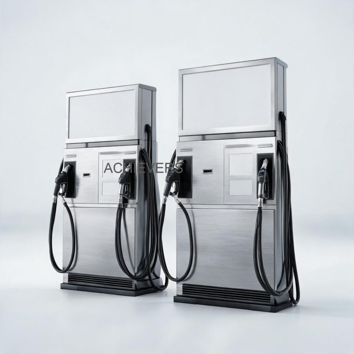
Accurate fuel accounting relies entirely on the integrity of your Fuel Dispensers. Whether you are dealing with a stationary AC unit at a construction depot or a mobile 24V DC bowser, symptoms like inaccurate meter readings, premature nozzle shutoff, and degraded flow rates share common root causes: air ingress, particulate fouling, voltage drops, and bypass valve maladjustment. This guide provides a systematic, engineering-led diagnostic framework to isolate and resolve these faults under harsh Indian site conditions—accounting for high ambient heat, monsoon-induced water ingress, heavy dust loads, and fluctuating power quality.
1. Quick Reference: How Fuel Dispensers Works
Understanding the operational sequence of Fuel Dispensers is critical for isolating faults. A modern commercial dispenser is not a single mechanism, but a finely tuned sequence of hydraulic and electronic stages:
- Prime and Suction: A continuously running electric motor (AC 220V/440V or DC 12V/24V) drives a high-capacity rotary gear pump. This creates a partial vacuum at the pump inlet, lifting fuel from the storage tank or barrel.
- Filtration and Air Elimination: Before entering the pump chamber, fuel passes through an inline strainer/filter to remove suspended solids. Concurrently, an air eliminator vents entrained air bubbles to prevent the meter from registering "phantom" volume.
- Pumping and Pressure Regulation: The rotary gear pump pressurizes the fluid. A built-in bypass valve (relief valve) ensures that if the nozzle is closed while the pump is running, fuel safely recirculates within the pump head without dead-heading the motor.
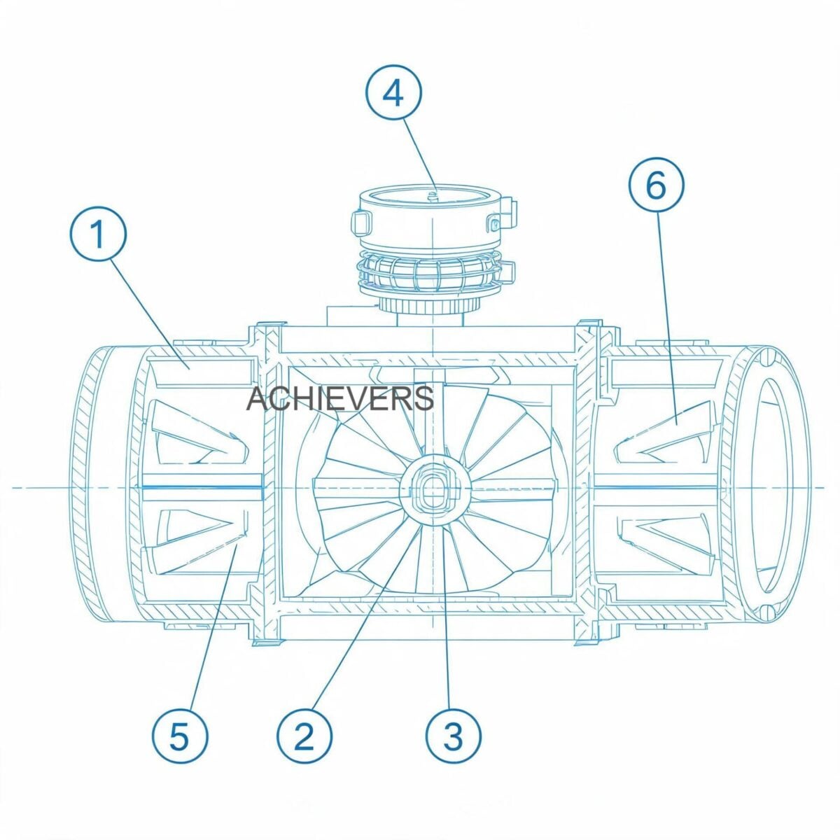
- Metering: Fuel enters the high-accuracy flow sensor (metering unit). The fluid forces internal mechanical components (typically gears or pistons) to rotate. An encoder translates this mechanical rotation into electronic pulses.
- Dispensing: Fuel travels through a 4-meter flexible rubber hose and exits via an auto-shutoff nozzle. The nozzle contains a venturi tube that detects changes in air pressure; when fuel hits the tip (indicating a full tank), the vacuum trips a mechanical latch, snapping the valve shut.
Technology Comparison: Metering Sensors in Dispensers
While Fuel Dispensers generally rely on positive displacement (PD) technology for high-accuracy commercial billing, it is important to understand how they compare to alternative metering mechanisms when designing a site's fuel architecture.
| Parameter | Positive Displacement (Gear/Oval) | Turbine Flow Meter | Notes for Indian Sites |
| :— | :— | :— | :— |
| Operating Principle | Measures discrete, trapped fluid volumes | Rotor speed proportional to fluid velocity | PD is standard for commercial dispensers due to precision. |
| Accuracy Standard | +/- 0.5% (Repeatability +/- 0.1%) | +/- 1.0% to 2.0% | PD meets stringent Indian Legal Metrology requirements. |
| Viscosity Immunity | Excellent (Higher viscosity improves seal) | Poor (Requires recalibration for fluid changes) | PD is superior for Indian diesel, which changes viscosity across seasons. |
| Pressure Drop | Moderate to High | Low | PD requires a robust, high-capacity gear pump to overcome restriction. |
| Susceptibility to Air | Measures air as liquid (Requires Eliminator) | Measures air as liquid | Both require mandatory air eliminators upstream of the meter. |
| Wear & Tear (Contaminated Fuel) | Susceptible to jamming from particulates | Bearings wear out quickly in dirty fuel | PD requires strict intermediate filtration, especially with adulterated fuel. |
'When to Use This Technology' Decision Matrix
- Choose Positive Displacement Dispensers When: You need Legal Metrology-compliant accuracy (+/- 0.5%), are dispensing expensive fluids (diesel, petrol), require batch tracking with resettable totalisers, and pump at consistent flow rates (up to 60 LPM). Ideal for fixed storage tanks and company transport hubs.
- Choose Turbine Meters When: You are monitoring unmetered bulk transfers at high flow rates (e.g., pipeline unloading) where +/- 1.0% accuracy is acceptable, and pressure drop must be minimized. Not recommended for precision retail-style dispensing.
2. Troubleshooting Matrix
When a dispenser fails, isolation is key. Below is an engineering-level diagnostic matrix to trace symptoms to their electro-mechanical roots.
| Symptom | Likely Cause | Diagnosis Steps | Fix / Corrective Action |
| :— | :— | :— | :— |
| Slow Flow Rate (< 20 LPM) | Clogged intermediate filter or strainer | Measure differential pressure across filter, or visually inspect mesh. | Remove, wash in clean solvent, blow with compressed air, and reinstall. |
| Slow Flow Rate (Motor Groaning) | Premature opening of internal bypass valve | Check if relief valve spring has lost tension or is jammed open by debris. | Disassemble bypass assembly, clean poppet, adjust spring tension screw. |
| Inaccurate Volume (Over-registering) | Air ingress in suction line | Inspect all suction pipe joints, unions, and PTFE tape for vacuum leaks. | Tighten fittings, replace damaged O-rings, ensure suction pipe is below fuel level. |
| Inaccurate Volume (Under-registering) | Meter wear or bypassed fuel | Perform a volumetric drawdown test into a calibrated 20L proving can. | Recalibrate the K-factor on the display. Replace flow sensor gears if heavily worn. |
| Premature Nozzle Shutoff | Blocked venturi port in nozzle tip | Inspect the small sensing hole at the tip of the dispensing nozzle. | Clear the sensing hole with a fine wire or compressed air. Do not enlarge the hole. |
| Dispenser Won't Start (No Display) | Power supply / voltage drop | Check incoming AC/DC voltage at the terminal block under load. | Correct wire gauge (especially for 12V/24V DC units), ensure secure ground. |
| Pump Runs, Zero Flow | Loss of prime / Cavitation | Check foot valve in the storage tank; listen for high-pitched whining. | Replace faulty foot valve. Ensure suction lift does not exceed pump specifications. |
| Display Flickers / Erratic Digits | EMI/RFI or loose encoder cable | Inspect connection between flow sensor pulser and main display PCB. | Reseat ribbon cables. Ensure the dispenser chassis is properly earthed. |
| Fuel Leakage from Pump Head | Blown shaft seal | Inspect for fuel weeping from the motor-pump coupling area. | Replace mechanical rotary shaft seal. Ensure bypass valve is not seized closed. |
| Batch Totaliser Fails to Reset | Keypad membrane failure | Test tactile feedback of the membrane switch. Check for moisture ingress. | Replace keypad membrane. Install a weather shield for monsoon protection. |
Engineering Note: Calibration and The K-Factor
Volumetric inaccuracy is rarely a total hardware failure; it is usually a calibration drift caused by minor mechanical wear over time. The electronic display calculates volume based on pulses received from the sensor:
Volume = Total Pulses / K-Factor
To determine the True Error Percentage during a proving run (using a Legal Metrology certified 20L measure):
True Error % = [(Indicated Volume – True Volume) / True Volume] * 100
If you dispense exactly 20.00 Liters into the proving can, but the dispenser display reads 20.20 Liters, the error is:
[(20.20 – 20.00) / 20.00] * 100 = +1.0%
To correct this, you must enter the dispenser's administrative menu and increase the K-Factor proportionally so the display requires more pulses to register a single liter, bringing the accuracy back within the +/- 0.5% specification.
3. Step-by-Step Field Diagnosis Procedure
When an operator reports a malfunctioning dispenser—whether it is slow flow, false readings, or erratic shutoffs—follow this sequential isolation procedure.
Tools Required: Digital multimeter, calibrated 20L proving measure, pressure/vacuum gauge, wire brush, fine needle/wire, compressed air, and standard spanners.
- Verify Power Quality Under Load: Do not just measure open-circuit voltage. Connect your multimeter to the incoming terminals and pull the nozzle trigger. For a 12V DC mobile dispenser, voltage dropping below 10.5V under load indicates insufficient wire gauge or a dying battery, which directly causes slow motor RPM and slow flow.
- Inspect the Nozzle Venturi (Premature Shutoff Check): If the pump runs well but the nozzle keeps clicking off, examine the auto-shutoff nozzle. Locate the small vacuum sensing port near the tip. If Indian site dust or mud has clogged this port, the nozzle acts as if it is submerged in fuel. Clear it carefully with a fine pin.
- Assess Suction Vacuum & Prime Integrity: If the pump runs but delivers zero or erratic flow, attach a vacuum gauge to the pump inlet. A high vacuum reading indicates a blocked suction line or stuck foot valve. A zero vacuum reading indicates an air leak in the suction piping (air is easier to pull than heavy diesel).
- Service the Intermediate Filter: Isolate the system and open the large capacity filter housing. Heavily adulterated diesel or rusted tank scaling will blind this filter rapidly. Wash the reusable mesh in clean solvent. A clogged filter is the #1 cause of slow flow and pump cavitation.
- Evaluate the Bypass (Relief) Valve: If the nozzle is fully open but flow is weak and the motor sounds strained, the internal bypass valve may be stuck open. This allows pressurized fuel to recirculate directly back to the suction side rather than pushing through the flow sensor. Disassemble, inspect the spring, and clean the poppet valve.
- Check the Flow Sensor Encoder: If fuel is flowing normally but the backlit display remains at 0.00, the mechanical meter is turning, but the electronic pulser is failing. Unplug and inspect the sensor cable. Look for corrosion from monsoon humidity or vibration-induced wire breaks.
- Perform a Legal Metrology Volumetric Test: Using a certified 20L proving measure, dispense fluid precisely to the zero mark on the can's sight glass. Compare the can's true volume to the dispenser's backlit display.
- Adjust Calibration: If the error exceeds +/- 0.5%, follow the manufacturer's specific key-sequence to enter calibration mode and adjust the K-Factor electronically. If the dispenser uses mechanical gear calibration, adjust the calibration screw on the meter head accordingly.
4. Installation and Setup Errors That Cause Ongoing Problems
Many troubleshooting calls originate from the day the equipment was installed. Commercial dispensers require specific hydraulic and electrical conditions to function reliably.
| Installation Error | Resulting Symptom | Engineering Correction |
| :— | :— | :— |
| Excessive Suction Lift | Cavitation, loud gear noise, highly erratic flow meter readings. | Move pump closer to tank. Maximum vertical lift should not exceed 3 meters. |
| Omission of a Foot Valve | Loss of prime. Pump runs dry for several minutes before dispensing starts. | Install a high-quality non-return valve (foot valve) at the bottom of the suction pipe. |
| Inadequate Wire Gauge (DC Models) | Motor overheats, flow rate drops from 60 LPM to <20 LPM. | Use minimum 4 sq.mm or 6 sq.mm copper cables for 12V/24V DC mobile installations. |
| No Vibration Isolation | Micro-fractures in pipe joints, leading to air ingress and fuel leaks. | Use flexible stainless steel bellows between hard site piping and the dispenser inlet. |
| Improper Earth Grounding | Erratic display jumps, static discharge risks, PCB burnout. | Drive a dedicated copper earth pit. Ensure ground resistance is < 2 ohms. |
| Direct Exposure to Elements | UV degrades the 4m rubber hose; heat fries the LCD screen. | Install a simple canopy. Indian summer sun (45°C+) causes severe vapor lock and electronics failure. |
5. Preventive Maintenance to Avoid Recurrence
Reactive maintenance is expensive. To maintain the +/- 0.5% accuracy and ensure continuous up to 60 LPM flow rates, implement a strict preventive schedule tailored to Indian site conditions.
- Weekly: Inspect the 4-meter rubber hose for bulges, cuts, or weeping at the crimps. Check the Fuel Nozzles for smooth trigger operation and clear venturi holes.
- Monthly: Drain water from the bottom of your bulk storage tanks. Water ingress is the primary destroyer of the high-accuracy flow sensor's internal machined surfaces. Wipe down the backlit display with a non-abrasive cloth to remove industrial dust.
- Quarterly (Pre-Monsoon): Open and thoroughly clean the internal large-capacity filter. Verify the integrity of weather seals around the electronic display housing. Ensure that Mobile Diesel Dispensers mounted on construction bowsers have secure mechanical mountings and zero cable chafing.
- Annually: Perform a formal calibration check against a Legal Metrology certified proving can. Replace the mechanical shaft seals if any weeping is detected.

6. When to Call Service vs. Fix Yourself
Knowing your team's limitations prevents accidental damage to expensive dispensing systems.
Fix Yourself (Site Engineer Level):
- Cleaning blocked nozzle venturi ports.
- Removing and washing the intermediate filter.
- Adjusting the bypass valve tension.
- Replacing damaged rubber hoses or auto-shutoff nozzles.
- Tightening suction lines and replacing standard O-rings.
- Performing electronic K-Factor calibration.
Call Factory Service / Lumen Instruments:
- Meter Head Seizure: If the internal positive displacement gears lock up due to hard particulates, the meter requires factory rebuilding and recalibration.
- PCB/Display Burnout: If a 440V phase-to-phase fault fries the main board, attempting to solder bypasses compromises the intrinsic safety of the unit.
- Legal Metrology Re-stamping: If your dispenser is used for commercial trade (selling to third parties), breaking the lead seal on the calibration unit requires a certified technician to recalibrate and re-stamp the unit legally.
- Motor Rewinding: Flameproof (FLP) motors used in hazardous zones must be repaired by PESO-certified workshops to maintain their explosion-proof integrity.
FAQ
Q: Why does my dispenser stop dispensing after 10 liters even when the trigger is pulled fully?
A: This is typically caused by a restricted suction line or a heavily clogged internal filter. The pump temporarily cavitates, dropping the flow rate and pressure so low that the auto-shutoff nozzle thinks the flow has stopped, releasing the latch. Clean the filter and check the foot valve.
Q: How frequently must we calibrate dispensers for internal accounting?
A: For internal company vehicles or mining equipment, calibrating once every 6 months is standard best practice. However, if you are pumping highly contaminated fuel, mechanical wear increases, and quarterly calibration checks using a 20L proving can are highly recommended.
Q: Can I use a 12V DC dispenser continuously for filling a 5000L tank?
A: No. Standard 12V/24V DC mobile dispensers typically have a 30-minute duty cycle. Running them continuously for hours will overheat the motor coils and degrade the bypass valve. For continuous bulk transfer, use a heavy-duty AC 220V/440V unit.
Q: What causes the flow rate to suddenly drop from 60 LPM to 20 LPM?
A: A sudden drop is usually a mechanical restriction: either the intermediate filter has blinded with debris/sludge, or the internal bypass valve spring has failed, causing fuel to loop internally rather than exiting the nozzle.
Q: How does voltage fluctuation affect the flow sensor?
A: Low voltage reduces motor RPM, dropping the flow rate, but it generally does not affect the accuracy of the positive displacement sensor, which measures volumetric displacement, not speed. However, severe voltage spikes can fry the encoder or reset the cumulative totaliser.
Q: Is premature shutoff always a faulty nozzle?
A: Not always. While a blocked venturi hole in the nozzle is the most common cause, excessive foaming in the diesel (caused by air leaks in the suction line) can cause foam to hit the nozzle tip, triggering the shutoff mechanism prematurely.
Q: How do I fix a backlit display that flickers during pumping?
A: Flickering under load points to a voltage drop or poor electrical grounding. Check the power terminal connections inside the dispenser. On mobile units, ensure the vehicle chassis ground is clean, tight, and free of rust.
Ensure your fuel accounting remains accurate and your fleet stays moving. If you are experiencing persistent flow rate drops, display errors, or require an upgrade to high-accuracy batching, our technical team is ready to assist. Contact Lumen Instruments today with your required flow rate, fluid type, and specific site conditions to get expert guidance on selecting or troubleshooting your Achievers fuel dispensing systems.