
In Indian industrial plants, mining sites, and large-scale commercial facilities, diesel generator sets are the backbone of continuous operations. However, unmonitored fuel consumption can lead to massive operational losses through inefficiency, mechanical degradation, or outright pilferage. When a Fuel Consumption Meters array begins to output zero readings, drops totalizer data, or displays erratic flow oscillations, the financial blind spot can cost a facility anywhere from ₹50,000 to ₹10,00,000 per month in untracked diesel usage.
Replacing an entire metering system at the first sign of trouble is a costly mistake. In many cases, the root cause lies in power fluctuations (common in Indian industrial grids), improper sensor orientation, air ingress in the fuel lines, or heavy contamination from adulterated diesel. This systematic engineering guide provides a rigorous diagnostic workflow for troubleshooting dual-sensor flow measurement systems, ensuring your plant maintenance team can isolate faults down to the specific sensor, cable, or hydraulic loop.
1. Quick Reference: How Fuel Consumption Meters Work
To effectively troubleshoot, one must understand the thermodynamic and mechanical principles governing the Fuel Consumption Meters. Modern high-capacity diesel engines (from 200 HP up to 2500 HP) do not consume all the fuel drawn by the lift pump. A significant portion of the fuel is circulated through the engine block to act as a coolant and lubricant for the injectors, returning to the diesel tank at a higher temperature.
To measure the net consumption accurately, an Achievers Fuel Consumption Meters employs a differential measurement architecture. It utilizes two distinct aluminum anodized positive displacement oval gear flow sensors.
The Engineering Formula for Net Consumption:
Net Diesel Consumed (C) = Inlet Fuel Volume (A) – Return Fuel Volume (B)
Where:
Volume (Liters) = Total Pulses Generated / Sensor K-Factor
The calculator continuously polls the pulse outputs from both the inlet sensor (a) and the return sensor (b). Because positive displacement meters trap exact volumetric pockets of fluid between the oval gears and the housing, the measurement accuracy is extremely high—rated at 0.1% Full Scale Deflection (FSD) per sensor, yielding a cumulative system accuracy of 0.5% of genuine consumption.
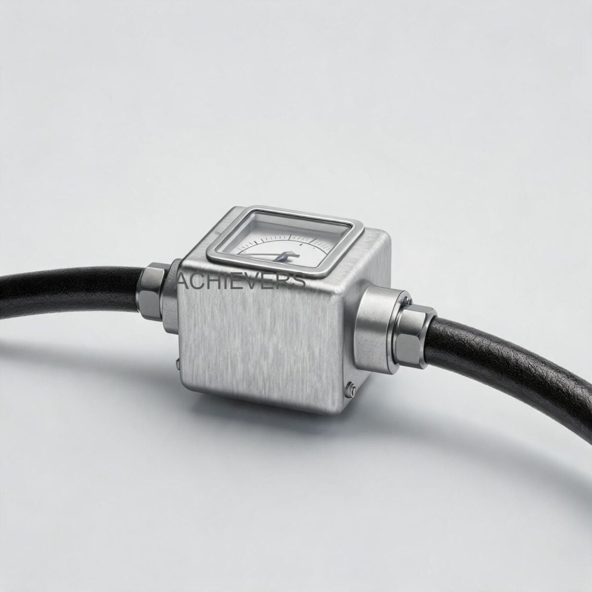
Technology Comparison Table: Why Oval Gear PD Meters?
Understanding why positive displacement technology is utilized for this application helps in ruling out environmental factors during troubleshooting. Here is how it compares to other technologies like Electromagnetic Flow Meters or Positive Displacement Flow Meters of varying types.
| Parameter | Oval Gear PD (Used in FCM) | Turbine Flow Meter | Electromagnetic Meter | Vortex Meter |
| — | — | — | — | — |
| Operating Principle | Volumetric trapping via gears | Velocity-based rotor | Faraday's Law of Induction | Von Karman effect |
| Viscosity Dependency | Accuracy improves with higher viscosity | High dependency (accuracy drops) | Independent | Requires low viscosity |
| Accuracy Rating | 0.1% FSD per sensor | 0.5% to 1.0% | 0.2% to 0.5% | 0.75% to 1.0% |
| Conductivity Requirement | None (Ideal for Diesel) | None | Requires conductive fluid (Not Diesel) | None |
| Straight Pipe Requirement | None (0D upstream/downstream) | High (10D upstream, 5D down) | Moderate (5D upstream) | High (10D to 15D) |
| Vibration Tolerance | Very High | Moderate | High | Poor |
When to Use This Technology: Decision Matrix
- Use Dual-Sensor Oval Gear PD Meters When: Measuring net consumption on modern Common Rail Direct Injection (CRDI) diesel engines, locomotive generators, earth-moving equipment, or marine engines where a high volume of return fuel exists.
- Use Single Sensor Inline Meters When: Transferring fuel from a storage tank to a day tank, where there is no return line loop.
- Do NOT Use This Technology When: Pumping heavily abrasive slurries, highly corrosive acids, or ultra-pure water (low lubricity will cause gear wear).
Specifications of Achievers Series Models
| FCM Model Number | Engine Capacity Match | Compatible Sensor Size | Material Construction | Power Supply Range |
| — | — | — | — | — |
| FCM:006 | Up to 200 HP | CE-006 (x2) | Aluminum Anodize | 5 Vdc to 24 Vdc |
| FCM:008 | 200 HP to 400 HP | CE-008 (x2) | Aluminum Anodize | 5 Vdc to 24 Vdc |
| FCM:012 | 400 HP to 1000 HP | CE-012 (x2) | Aluminum Anodize | 5 Vdc to 24 Vdc |
| FCM:020 | 1000 HP to 1500 HP | CE-020 (x2) | Aluminum Anodize | 5 Vdc to 24 Vdc |
| FCM:025 | 1500 HP to 2000 HP | CE-025 (x2) | Aluminum Anodize | 5 Vdc to 24 Vdc |
2. Troubleshooting Matrix
When encountering instrumentation failure on site, use the following matrix to identify the root cause before dismantling the pipework.
| Symptom | Likely Cause | Diagnosis Steps | Fix |
| — | — | — | — |
| Totalizer Reads Absolute Zero | No DC power reaching the flow calculator. | Check engine battery voltage and wiring terminals for 5 Vdc to 24 Vdc. | Replace blown fuse; reconnect loose battery terminals. |
| Flow Rate is Zero but Powered On | Oval gears mechanically jammed. | Isolate sensors. Open Y-strainer. Inspect for debris or rust. | Clean Y-strainer. Manually flush sensors with clean diesel. |
| Unstable/Oscillating Flow Rate | Air ingress in the inlet fuel line. | Check for foaming in the fuel lines or loose hose clamps upstream. | Tighten all upstream fittings; bleed air from the fuel system. |
| Negative Consumption Reading | Inlet and Return sensors swapped. | Compare pulse rates of Sensor A (inlet) vs Sensor B (return). | Re-terminate the wiring at the calculator or physically swap lines. |
| Readings Drifting Higher Over Time | Return line restriction or blockage. | Monitor engine backpressure. Check return line routing to the tank. | Clear return line blockages to allow unhindered flow back to tank. |
| Missing RS-485 / GPRS Data | Communication cable EMI interference. | Check shielding on data cables. Verify baud rate settings. | Reroute data cables away from alternator; ground the shield at one end. |
| Engine Stalling / High Pressure Drop | Undersized meter or severely clogged strainer. | Check model capacity (e.g., CE-006 on a 500HP engine is incorrect). | Upgrade to correct model (e.g., CE-012); clean 60-micron Y-strainer. |
| Fuel Leakage from Sensor Body | O-ring failure due to over-pressurization. | Check lift pump output pressure against meter specifications. | Replace O-rings; install a pressure regulating valve if necessary. |
| Abnormal Mechanical Noise | Vertical installation of gear shafts. | Visually inspect sensor orientation against gravity. | Remount sensor block so oval gear shafts are strictly horizontal. |
| Erratic Calculator Display | Voltage spikes from generator starter. | Measure voltage during engine crank. Look for drops below 5V. | Install an isolated DC-DC converter for the meter power supply. |
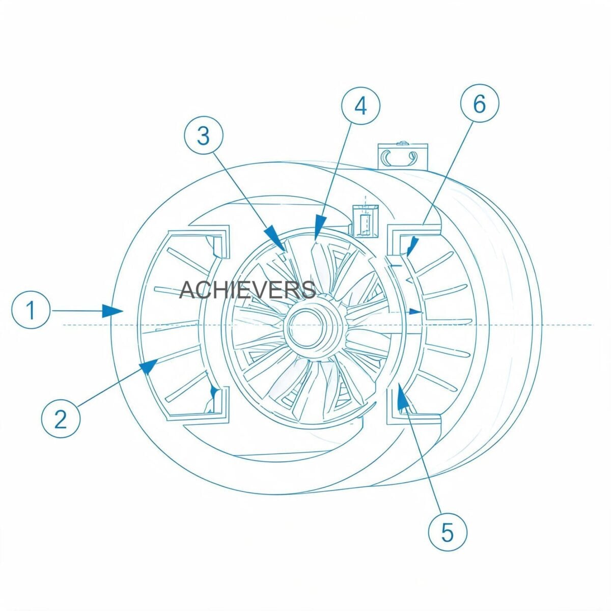
3. Step-by-Step Field Diagnosis Procedure
When a zero reading, missing totals, or unstable flow rate is reported, Indian maintenance teams should execute the following 8-step diagnostic workflow using a digital multimeter (DMM), a set of Allen keys, a precision screwdriver, and a calibrated volumetric flask.
Step 1: Validate DC Power and Grounding Integrity
Using a DMM, probe the power input terminals at the flow calculator. The Achievers system is designed to operate on an onboard engine battery supply ranging from 5 Vdc to 24 Vdc (capable of handling up to 29 Vdc peak). Ensure that voltage does not sag below 5 Vdc during engine cranking. A floating ground can cause erratic pulse counting; verify that the negative terminal is securely bonded to the engine chassis ground.
Step 2: Inspect the Upstream Y-Strainer
Indian diesel is frequently subject to dust ingress and heavy sediment. Isolate the fuel lines using the block valves. Open the Y-type strainer installed upstream of both the inlet and return sensors. Extract the mesh and inspect for rust flakes, sludge, or biological growth (diesel bug). A clogged strainer causes fuel starvation and zero readings. Clean the mesh with compressed air and a solvent.
Step 3: Verify Oval Gear Mechanical Freedom
If the calculator is powered but registers zero flow while the engine is running, the oval gears may be seized. Bypass the engine, remove the sensor cover, and gently push the aluminum anodized gears with a non-metallic probe. They should spin freely. If they are bound, clean the internal chamber of any particulate matter that bypassed the strainer.
Step 4: Execute a Pulse Signal Check (Hall Effect Verification)
Disconnect the signal wires from the flow calculator. Provide 5-24 Vdc to the sensor directly. Connect your DMM (set to frequency or DC voltage) across the signal and ground wires. Slowly blow compressed air through the sensor to rotate the gears. You should observe a rapid fluctuation in voltage (square wave pulse) corresponding to gear rotation. If there is no pulse, the Hall effect pickup board requires replacement.
Step 5: Check for Air Entrainment and Cavitation
Unstable, oscillating flow rates are almost always hydraulic, not electronic. Check the suction side of the lift pump. Even a microscopic pinhole in a fuel hose will draw air under vacuum. Because positive displacement meters measure total volume, they will measure entrained air bubbles as fuel, causing erratic spikes in the reading. Bleed the fuel lines completely.
Step 6: Confirm Correct Sensor Orientation
A critical but common installation error. The flow sensors must be installed such that the internal rotor shafts are perfectly horizontal. If installed vertically, the weight of the rotors rests unevenly on the thrust bearings, causing premature wear, mechanical drag, and eventually a seized meter (resulting in a zero reading).
Step 7: Analyze the Inlet vs. Return Differential
If the fuel consumption totals appear wildly inaccurate, check the differential logic. The system uses Total = (a) – (b). If the flow rate of the return line (b) is erroneously reading zero due to a broken wire, the calculator will assume 100% of the inlet fuel is being consumed, resulting in massive over-reporting. Conversely, if the wires are swapped, you will get a negative consumption error.
Step 8: Volumetric Bucket Test (Calibration Verification)
To prove system accuracy (rated at 0.5% of genuine consumption), perform a bucket test. Route the engine return line into a calibrated 20-liter jerry can instead of the main tank. Run the engine from a secondary calibrated container. Compare the physical volume difference between the two containers against the digital output on the flow calculator. If a discrepancy exists, recalibrate the K-factor via the device's setup menu.
4. Installation and Setup Errors That Cause Ongoing Problems
A large percentage of measurement failures stem from the day the unit was installed. Below are common setup errors that plague industrial sites.
| Installation Error | Symptom Manifestation | Corrective Engineering Action |
| — | — | — |
| Mounting close to high-heat exhaust manifolds | Electronics failure, vapor lock, blank screen. | Relocate meter to a cooler zone; max operating temp usually 80°C. |
| Running signal cables parallel to 415V AC power lines | High erratic flow rates even when engine is off (EMI noise). | Use shielded twisted-pair cables. Route DC signal lines perpendicular to AC power lines. |
| Omitting the required Y-Type Strainer | Oval gears jamming frequently with rust/debris. | Install the provided Y-strainer directly upstream of the inlet sensor. |
| Installing sensors with vertical gear shafts | Scraping noises, drifting accuracy, premature lock-up. | Reorient the mechanical block so gear shafts lie flat horizontally. |
| Sharing DC power source with heavy inductive loads (starter motors) | Calculator reboots randomly, missing batch totals. | Provide an isolated 24 Vdc power supply or use a voltage stabilizer. |
| Incorrect K-factor entered during setup | Consistent under-reporting or over-reporting of fuel usage. | Recalculate and input correct K-factor specific to the CE-series sensor. |
5. Preventive Maintenance to Avoid Recurrence
Maintaining a high-accuracy instrumentation system requires routine care, especially when subjected to the harsh ambient heat, heavy monsoon humidity, and dusty environments characteristic of Indian mining, telecom, and construction sites.
Weekly Maintenance:
- Perform a visual inspection of the Y-type fuel strainer. Drain any accumulated water from the fuel-water separators upstream of the meter.
- Check the flow calculator display for error codes or warning lights.
Monthly Maintenance:
- Inspect the electrical harnesses. Heavy vibrations from massive 1500 HP to 2000 HP diesel engines can fray cable insulation. Verify that the M12 connectors or terminal blocks are tight.
- Cross-reference the mechanical totals on the meter with the engine’s stated fuel consumption curve at a specific load factor (e.g., 75% load) to spot early signs of drift.
Annual Maintenance:
- Schedule a complete calibration verification.
- Open the aluminum anodized sensor body and inspect the oval gears for pitting or abrasive wear.
- Verify the integrity of the O-rings and replace them to prevent seepage.
- Test the RS-485 / RS-232 / Pulse outputs to ensure the GPS and GPRS remote tracking modems are receiving accurate telemetry data.
6. When to Call Service vs. Fix Yourself
Knowing the limits of field maintenance prevents accidental destruction of precision instruments.
Fix Yourself:
- Clearing clogged strainers and bleeding air from hydraulic lines.
- Tightening loose electrical terminals and checking battery voltage.
- Adjusting the display parameters (changing units from Liters to Gallons or M3).
- Correcting the physical orientation of the sensor body.
Call Lumen Instruments / Factory Service:
- If the aluminum oval gears show deep gouges or structural damage from pumping hard particulate matter.
- If the flow calculator PCB is burnt out due to a massive voltage surge (e.g., lightning strike or alternator regulator failure).
- If the unit consistently fails the volumetric bucket test even after manual K-factor adjustments, indicating severe internal volumetric bypass (slip).
FAQ
Q: Why does my flow calculator turn off when the generator starts cranking?
A: During cranking, the starter motor draws massive current, causing the engine battery voltage to drop below the meter’s 5 Vdc minimum threshold. Install a dedicated 12V/24V power supply or a DC-DC converter with a wide input range to stabilize power.
Q: Can I use this meter to track fuel theft directly?
A: Yes. Because the system continuously calculates Total Consumption = Inlet - Return, any sudden drop in fuel tank levels that does not correspond with the meter's consumption data heavily indicates physical theft or a severe tank leak. You can transmit this data via the RS-485 output to your GPS/GPRS tracking software.
Q: The display shows a flow rate, but the totalizer isn't accumulating. What's wrong?
A: This is typically a software parameter issue or a memory failure. Ensure the device isn't in a 'calibration' or 'test' mode. If settings are correct and totals still don't accumulate, the internal EEPROM chip may be damaged, requiring a calculator replacement.
Q: How often do I need to clean the Y-strainer on an Indian construction site?
A: Due to high levels of dust and potential fuel adulteration in remote areas, inspect the strainer weekly during the first month. Adjust the frequency based on the debris found. In highly contaminated environments, weekly cleaning is mandatory to prevent gear jamming.
Q: My return line flow rate is higher than my inlet flow rate. How is this possible?
A: This is physically impossible unless the engine is producing fuel. The electrical wiring for the inlet and return sensors has been swapped at the calculator terminals, or the inlet sensor is clogged/jammed while the return sensor is freely spinning due to fuel expanding under heat.
Q: Does ambient heat (up to 45°C in Indian summers) affect the meter's accuracy?
A: The aluminum anodized construction handles high ambient heat exceptionally well. However, fuel expands with heat. If the return fuel is significantly hotter than the inlet fuel, volumetric expansion occurs. The dual-sensor system is calibrated to handle standard engine differentials, but extreme cases may require temperature compensation algorithms.
Q: I have a 1200 HP diesel engine. Which model do I need?
A: According to the selection guide, you require the FCM:020 model, which utilizes the CE-020 flow sensors designed to handle flow rates for 1000 HP to 1500 HP diesel engines without causing excessive backpressure on the lift pump.
Are you dealing with persistent measurement errors, or are you looking to upgrade your fleet's fuel tracking to prevent diesel theft? Contact our engineering team with your engine horsepower, maximum flow rate requirements, and operating site conditions. We will help you select, calibrate, and install the exact fuel consumption metering system to secure your bottom line.