Accurate steam measurement in Indian boiler houses has historically been a persistent challenge for plant engineers. Given the high cost of boiler fuels—whether coal, bagasse, or furnace oil—steam is no longer treated as a cheap utility; it is a premium energy commodity costing anywhere from ₹2,000 to ₹4,000 per ton to generate. Relying on outdated differential pressure (DP) orifice plates often results in massive energy accounting errors, high pressure drops, and poor turndown ratios. When boiler load fluctuates during batch processes, traditional meters fail to capture the peaks and valleys, leading to skewed mass-balance calculations and hidden energy losses.
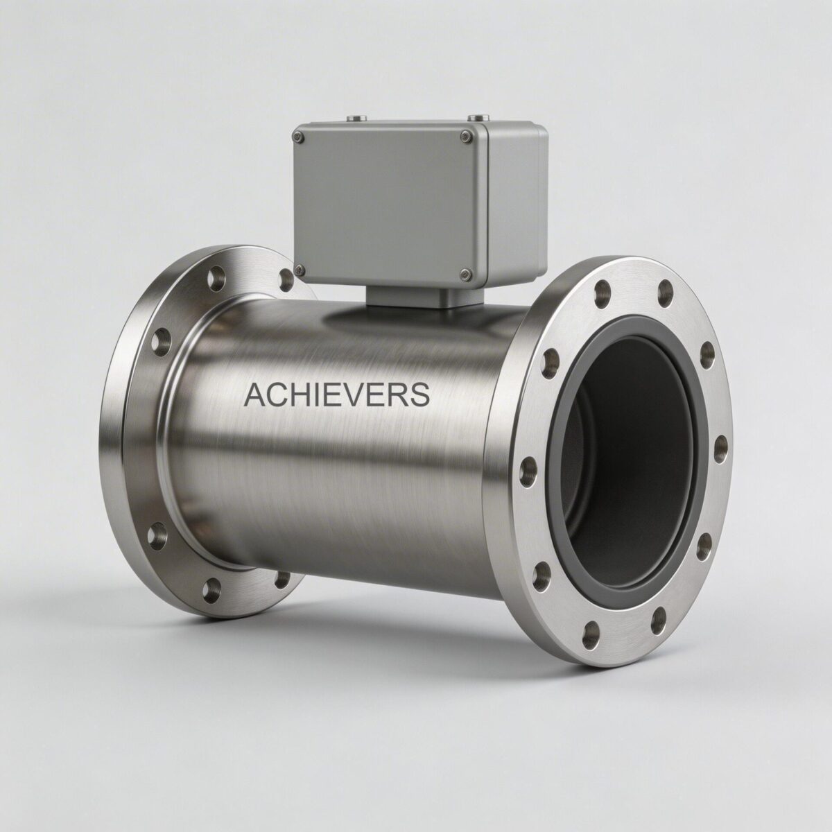
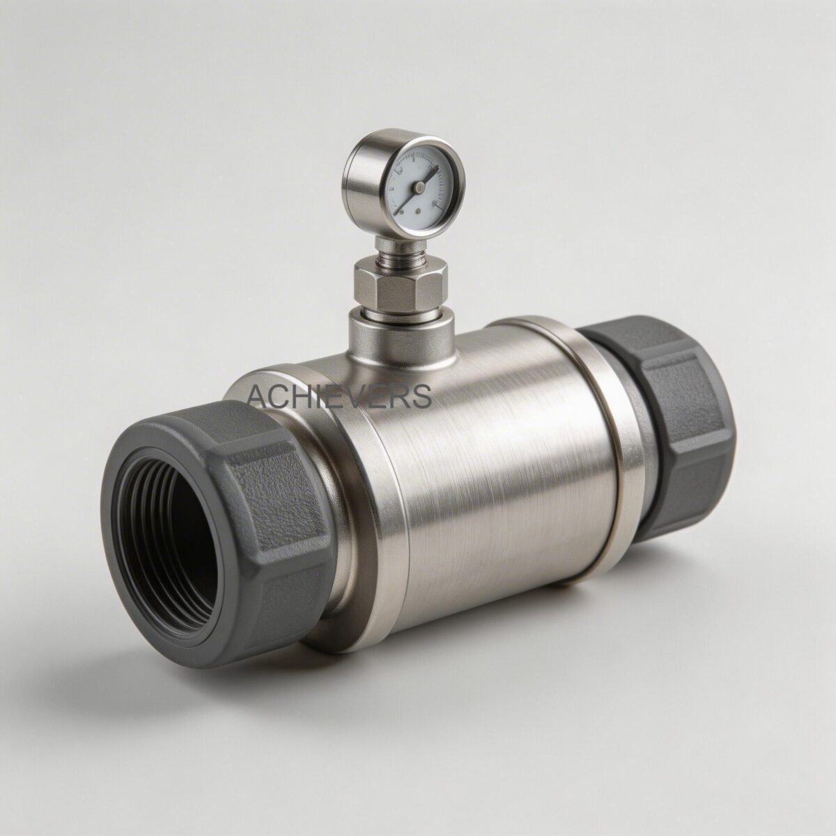
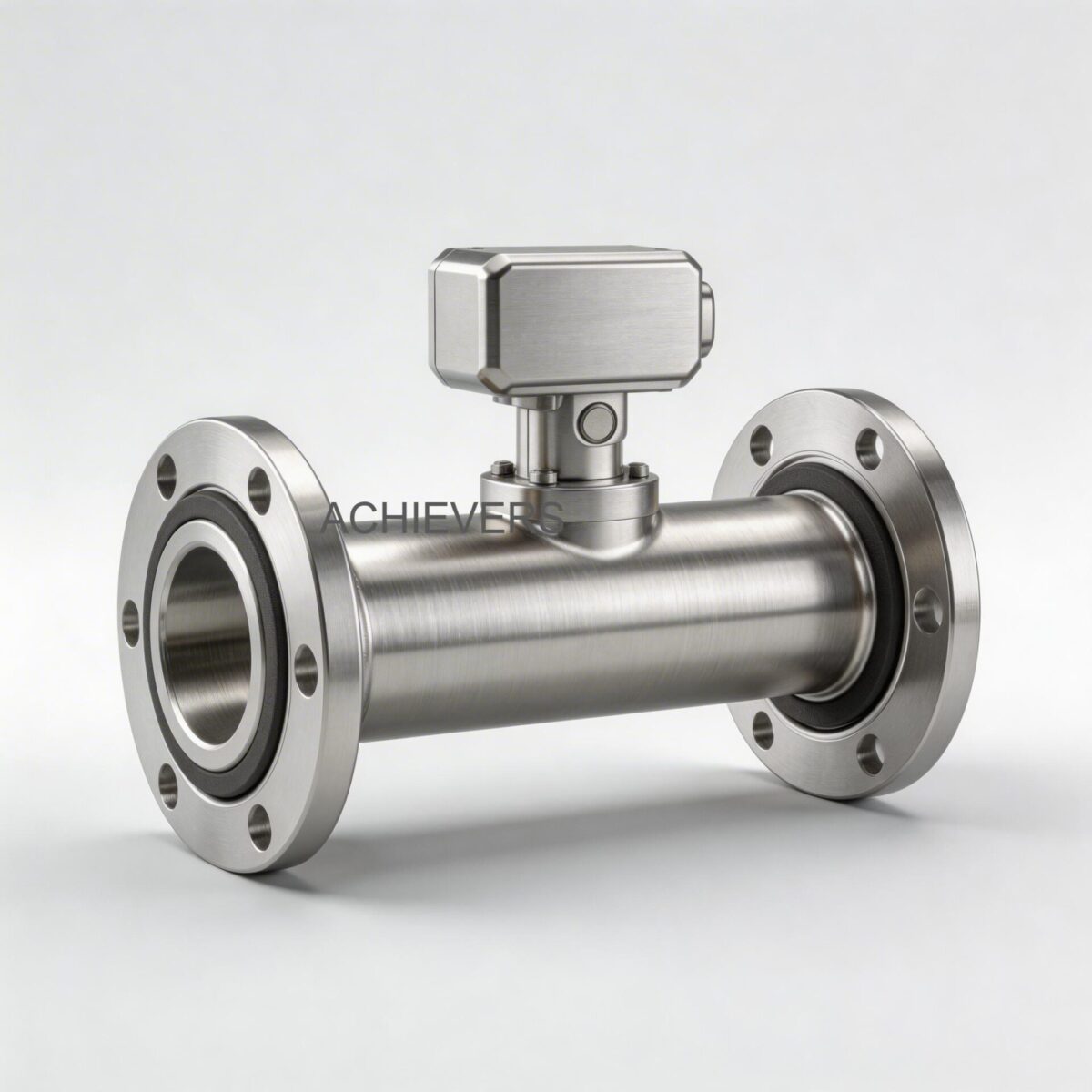
Modern instrumentation engineers recognize that solving this requires technology capable of handling the dynamic states of steam. Vortex Flow Meters have emerged as the industry standard for steam flow measurement. Operating on the principle of the Karman vortex street, these meters provide direct volumetric flow measurement with high turndown ratios and no moving parts to wear out. For Indian steam plants, integrating meters with inbuilt pressure and temperature compensation is critical. This ensures that as boiler headers experience standard pressure fluctuations, the instrument dynamically calculates the exact steam density, delivering accurate mass flow data to the DCS or SCADA system.
1. Industry Overview: The Fluid Challenge
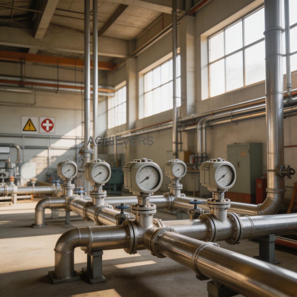
Steam generation and distribution in India span across diverse sectors, from the pharmaceutical hubs in Baddi to the textile processing units in Tirupur and the massive petrochemical complexes in Gujarat. Across these industries, the fundamental fluid challenge remains the same: steam is a compressible fluid. Its density changes drastically with variations in pressure and temperature.
In a typical Indian process plant, a boiler might be rated to deliver saturated steam at 10.5 kg/cm². However, due to sudden steam draw from process vessels, header pressure frequently dips to 8 kg/cm² or surges when valves close. If a flow meter assumes a constant pressure (as uncompensated DP meters do), a 10% drop in pressure can result in up to a 5% error in mass flow readings. Over a month, this translates to lakhs of rupees in unaccounted thermal energy.
Furthermore, poor insulation and long pipe runs in Indian plants often lead to wet steam conditions. Water droplets entrained in the steam line can erode moving parts in mechanical meters and cause erratic readings in sensitive electronic sensors. The industrial environment itself is harsh, characterized by high ambient temperatures up to 50°C during summers, 95% humidity during the monsoons, and frequent voltage fluctuations. Measuring instruments must strictly comply with the Indian Boiler Regulations (IBR) and feature robust enclosures and electronics to survive.
2. Product Capabilities Matched to Industry Needs
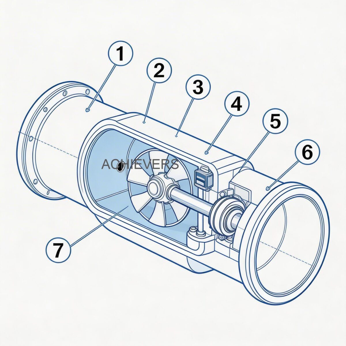
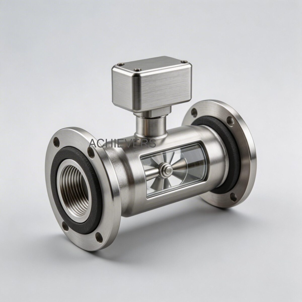
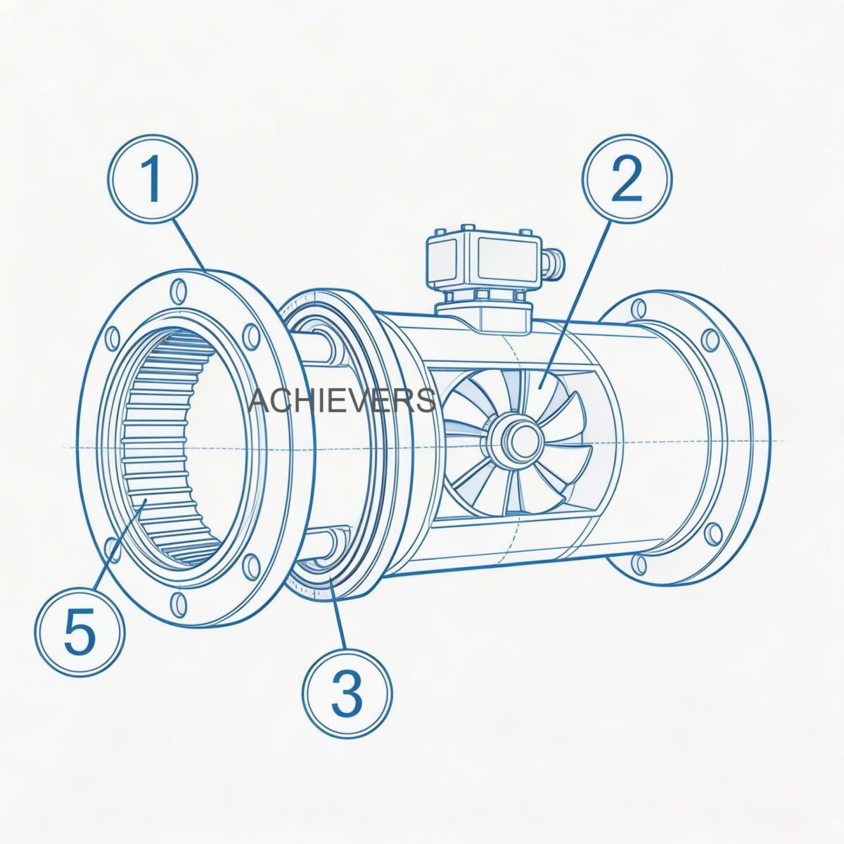
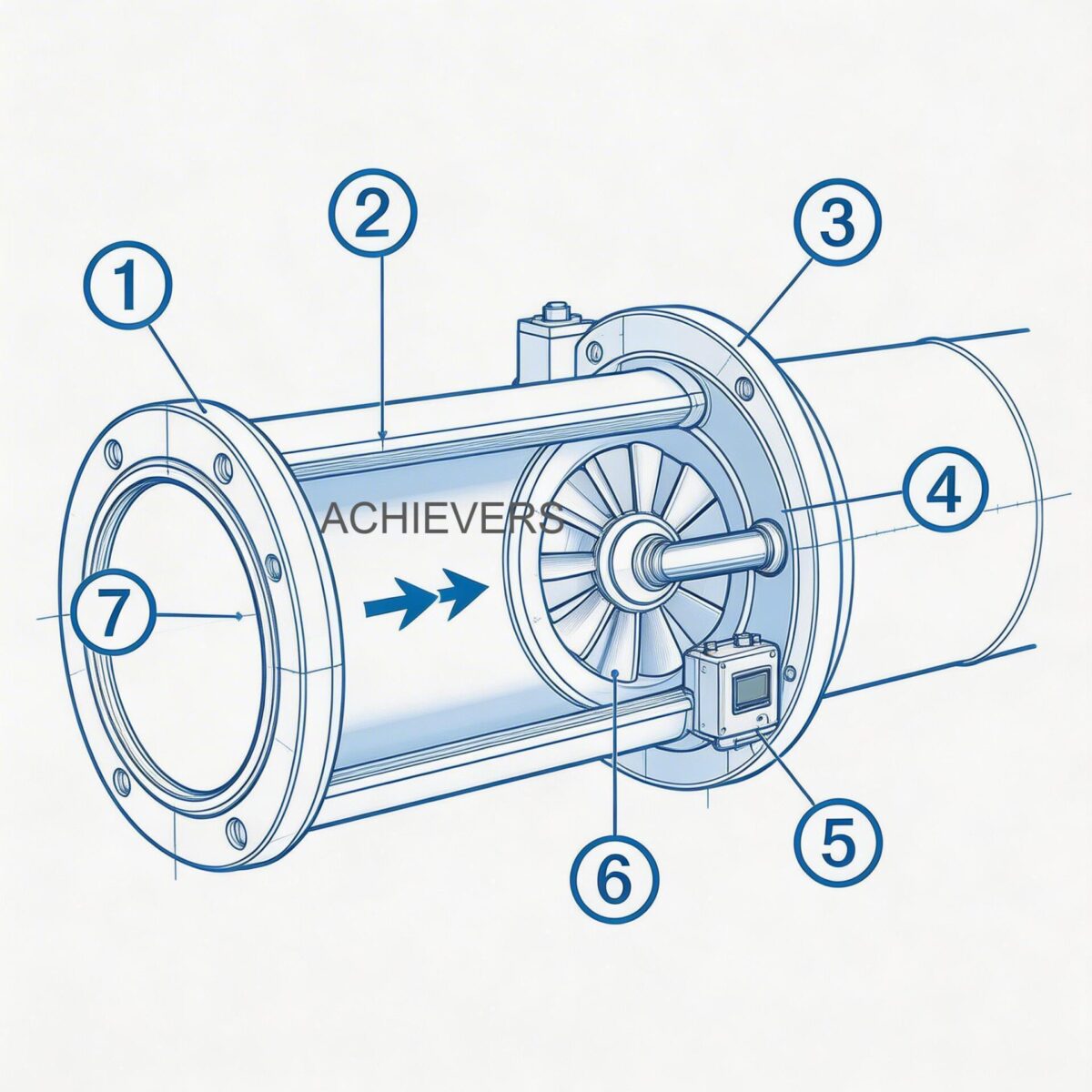
The core technology behind Vortex Flow Meters relies on a physical phenomenon known as the von Karman effect. When a bluff body (a non-streamlined obstacle) is placed in the path of the steam flow, it causes the fluid to separate and generate alternating vortices downstream.
Engineering Principle:
The frequency of these shedding vortices is directly proportional to the fluid velocity. The mathematical relationship is expressed as:
f = (St x V) / d
Where:
- f = Frequency of vortex shedding (Hz)
- St = Strouhal number (a dimensionless calibration constant unique to the bluff body design)
- V = Velocity of the steam flow (m/s)
- d = Width of the bluff body (m)
Because the Strouhal number remains constant over a wide range of Reynolds numbers, the vortex meter provides excellent linear accuracy. To calculate mass flow, the meter uses its inbuilt temperature and pressure compensation to determine real-time density, multiplying the calculated volume by this dynamic density value.
Industry Needs vs. Lumen Instruments Specifications
| Industry Requirement | Vortex Flow Meter Feature | How It Addresses the Need |
| :— | :— | :— |
| Wide Pipe Size Variations | Line Size: DN 15 to DN 300mm | Covers everything from small process heating jackets (DN 15) to massive main boiler distribution headers (DN 300). |
| High Thermal Stress | Temp Rating: -50 to 350°C | Safely handles high-temperature superheated steam in cogeneration power plants without sensor degradation. |
| Standard Boiler Pressures | Pressure Rating: 20 kg/cm² | Ideal for 90% of industrial process steam applications in India (typically 3 to 15 kg/cm²). |
| Dynamic Density Changes | Inbuilt P & T Compensation | Automatically corrects mass flow readings when boiler pressure fluctuates, preventing energy billing errors. |
| DCS / SCADA Integration | Output: 4-20 mA, Pulses, RS 485 Modbus | Allows seamless integration into plant automation systems for real-time energy monitoring and data logging. |
| Power Fluctuation Resilience | Power: 24Vdc two-wire | Industry-standard loop-powered design minimizes wiring costs and is easily isolated against voltage spikes. |
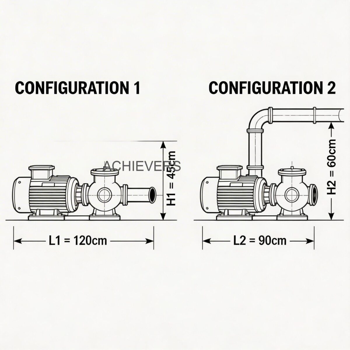
| Space & Piping Constraints | Mounting: Flange / Sandwich (Wafer) / Clamp On | Sandwich type saves face-to-face space and installation cost, while Flange type ensures high-pressure IBR compliance. |
| No Moving Parts | Solid-state bluff body sensor | Eliminates mechanical wear from wet steam, avoiding the frequent recalibrations required by turbine meters. |
Technology Comparison Matrix
To understand why this is the preferred choice, engineers must compare it against other common flow technologies. While Electromagnetic Flow Meters are exceptional for conductive liquids like cooling water, they cannot measure gases or steam.
| Parameter | Vortex Flow Meter | Orifice Plate (DP) | Turbine Flow Meter |
| :— | :— | :— | :— |
| Primary Steam Use | Excellent for Saturated & Superheated | Good, but outdated | Poor (Bearings fail) |
| Turndown Ratio | 20:1 to 30:1 | 3:1 to 4:1 (Very narrow) | 10:1 |
| Pressure Drop | Low to Moderate | Very High (Wastes energy) | Moderate to High |
| Maintenance Need | Very Low (No moving parts) | High (Impulse lines clog/freeze) | High (Bearing wear) |
| Accuracy Rating | ±1.0% of reading (with compensation) | ±2.0% to ±3.0% of full scale | ±1.0% but degrades over time |
| Installation Cost | Moderate | High (Needs manifolds, DP transmitters) | Low to Moderate |
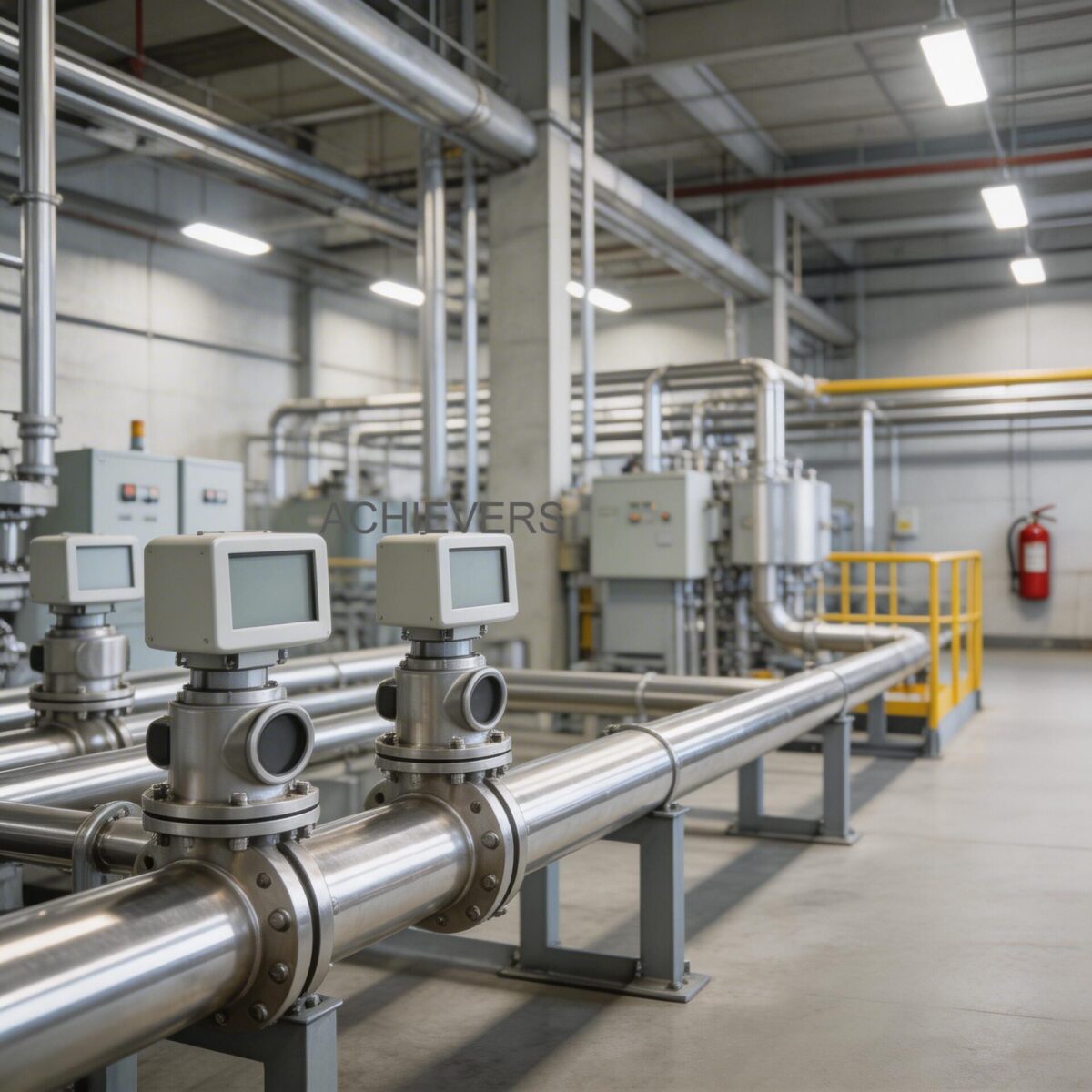
3. Typical Installation Scenarios in This Industry
Implementing Vortex Flow Meters correctly depends heavily on the specific application within the utility infrastructure. Here are three standard scenarios in Indian industrial plants.
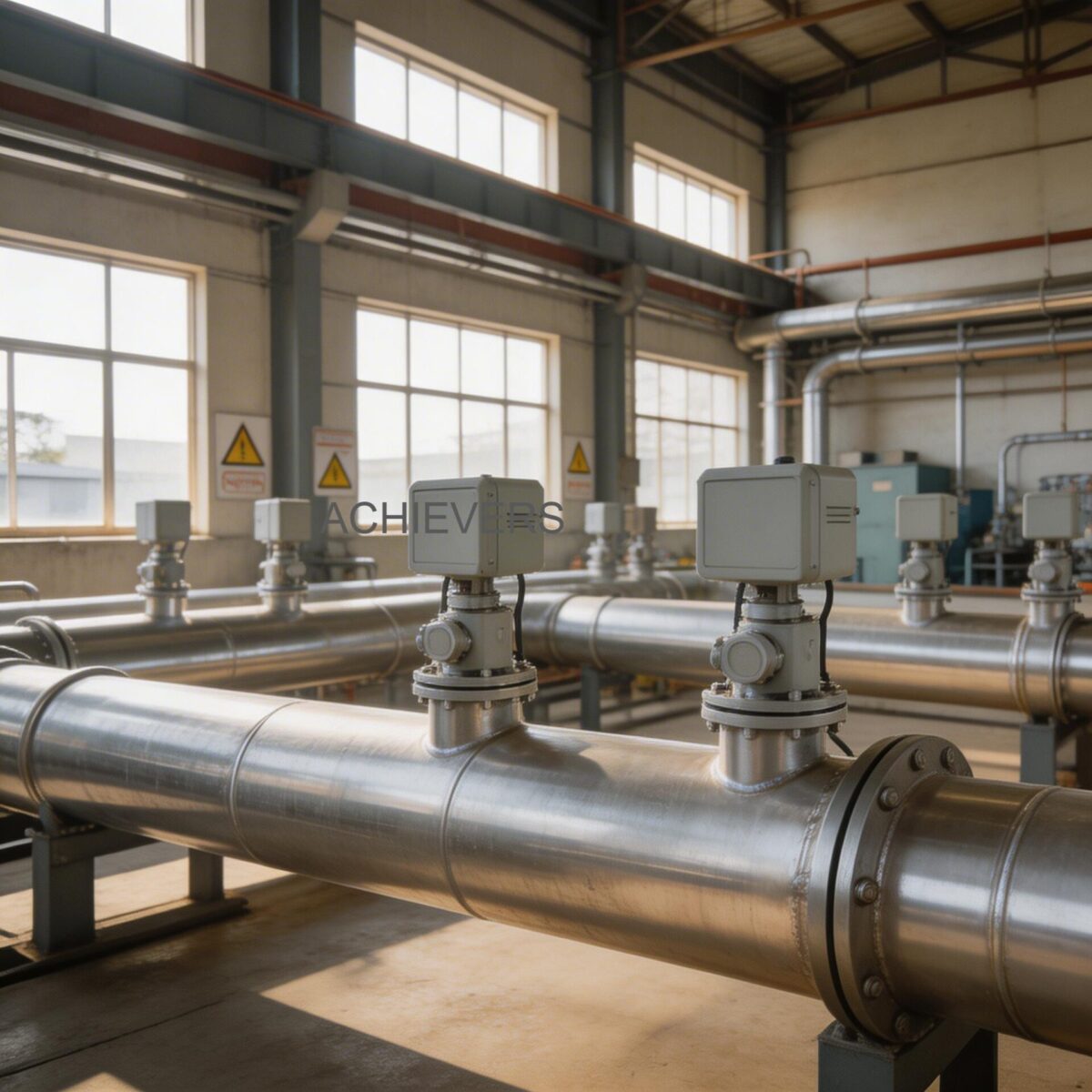
Scenario A: Main Boiler Header (Saturated Steam)
In a 10 TPH (Tonnes Per Hour) coal-fired boiler, the main steam header distributes energy to the entire plant.
- Challenge: Pressure fluctuates based on load, and any pressure drop across the flow meter wastes boiler fuel.
- Configuration: Flange type, DN 150 to DN 200 size, utilizing inbuilt pressure and temperature compensation.
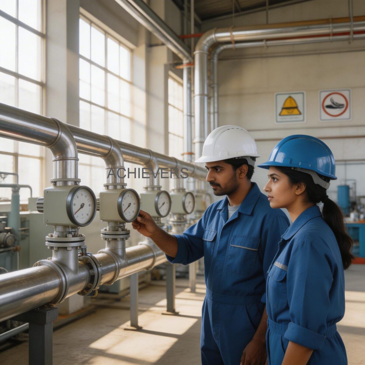
- Key Setting: The meter is configured via RS 485 Modbus to transmit compensated mass flow (kg/hr or TPH) directly to the boiler house DCS. A straight pipe run of at least 15D upstream and 5D downstream is strictly enforced to ensure a uniform flow profile.
Scenario B: Individual Process Utility Lines (Textiles & Pharma)
Different departments (e.g., dyeing in textiles or sterilization in pharma) are billed internally for the steam they consume.
- Challenge: Limited space in pipe racks and the need for cost-effective, multi-point measurement.
- Configuration: Sandwich type (wafer style) meters for DN 50 to DN 80 lines. Sandwich mounting reduces the overall face-to-face dimension, allowing insertion into tight piping layouts.
- Key Setting: Pulse output is fed to a local batch controller or totalizer. Pressure compensation is often localized based on a standard known PRV (Pressure Reducing Valve) setting to optimize instrumentation budgets.
Scenario C: Co-Generation Power Plants (Superheated Steam)
Sugar mills and large chemical plants generate their own power using back-pressure turbines.
- Challenge: Temperatures can exceed 300°C, and velocities are exceptionally high.
- Configuration: High-temperature Flange type rated for 350°C and up to 20 kg/cm² pressure.
- Key Setting: 4-20 mA output mapped tightly to the turbine feed rates. The bluff body must be meticulously specified to handle the acoustic noise and high Reynolds numbers associated with superheated steam flows.
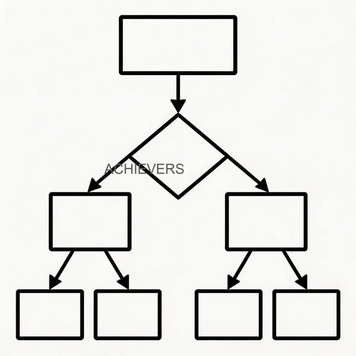
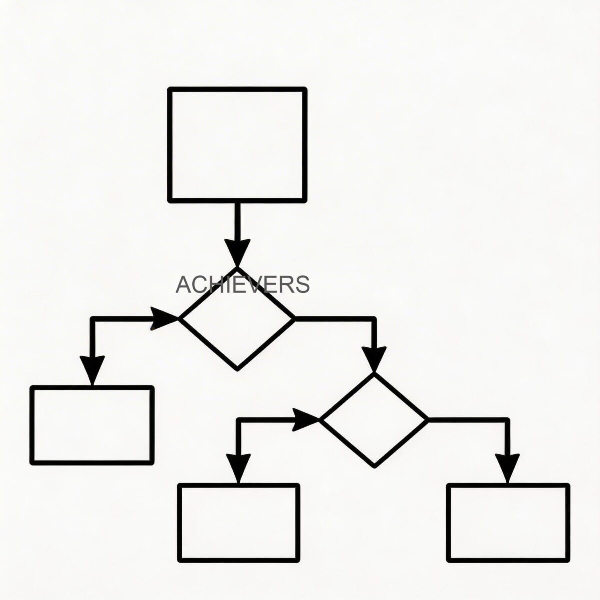
"When to Use This Technology" Decision Matrix
- Use Vortex IF: You are measuring saturated steam, superheated steam, or compressed air; you need a high turndown ratio (to capture both peak loads and weekend minimums); and you want to eliminate impulse line maintenance.
- Do NOT Use Vortex IF: The fluid velocity is extremely low (below the critical Reynolds number required to form vortices); the fluid is highly viscous (heavy fuel oils); or the pipe vibrates excessively at the exact resonant frequency of the sensor.
4. Compliance, Accuracy, and Certification Requirements
Procurement for steam applications in India is heavily regulated. A ₹1,00,000 meter is useless if the boiler inspector rejects it.
Indian Boiler Regulations (IBR):
Any pipe or fitting attached to a boiler or steam line operating above 3.5 kg/cm² generally falls under IBR purview. Vortex flow meters used in these applications must often feature IBR-certified flanges (such as WCB carbon steel or SS316 with appropriate heat certificates).
Accuracy and Legal Metrology:
For custody transfer—where a utility company sells steam to a neighboring plant in an industrial park—Legal Metrology compliance may be required. The inbuilt compensation ensures that the mass flow calculation maintains an accuracy of ±1.0% to ±1.5% of the reading. Without inbuilt density compensation, uncompensated volumetric meters can drift by 5-10% during pressure shifts, resulting in massive financial disputes.
Environmental Protection:
Given the Indian monsoon, the electronics housing must be IP65 or IP67 rated. The 24Vdc two-wire system must also feature robust galvanic isolation to protect the sensitive piezoelectric sensors from ground loops and voltage transients common in semi-urban industrial grids.
5. ROI and Operational Benefits
The capital expenditure for upgrading from an old orifice plate to a compensated vortex meter is typically recovered within 3 to 6 months through energy savings and accurate billing alone.
| Operational Benefit | Typical Improvement | Indian Industry Context |
| :— | :— | :— |
| Energy Mass-Balance | Reduces unaccounted steam losses from 8% to under 2%. | Crucial for ISO 50001 audits and optimizing the Steam-to-Fuel ratio of expensive imported coal. |
| Maintenance Reduction | Eliminates weekly blowing down of impulse lines. | Frees up boiler operators from hazardous maintenance tasks, reducing labor costs and downtime. |
| Turndown Ratio Expansion | Captures accurate flow even at 10% of maximum load. | Indian plants often run at partial capacity during night shifts; DP meters read zero at low flows, whereas vortex meters keep measuring. |
| Pressure Drop Recovery | Permanent pressure loss is drastically lower than orifice plates. | Saves boiler feed pump energy and allows boilers to be run at slightly lower header pressures, saving fuel. |
6. Selection Checklist for This Industry
To ensure you procure the correct specification for your plant, use this engineering checklist before contacting your supplier:
- Specify the Exact Fluid State: Is it saturated steam, superheated steam, or wet steam? State the estimated wetness fraction if known.
- Determine Operating Pressure & Temperature: Note the normal, minimum, and maximum values. Ensure the maximum pressure does not exceed the 20 kg/cm² rating and the max temperature is within 350°C.
- Calculate Line Size vs. Flow Rate: Do not merely match the existing pipe size. Calculate the steam velocity to ensure it falls within the meter's linear measuring range. Sometimes a DN 100 pipe requires a DN 80 meter (with reducers) to keep velocity optimal.
- Choose the Mounting Style: Select Flange type for IBR high-pressure lines, or Sandwich (wafer) type to save cost and space on low-pressure process lines.
- Verify Compensation Requirements: Confirm that the model ordered includes inbuilt pressure and temperature compensation to deliver mass flow output.
- Select Output Protocol: Decide between 4-20 mA, pulse outputs for local totalizers, or RS 485 Modbus for multi-parameter DCS integration.
- Confirm Power Availability: Ensure your control panel can supply stable 24Vdc two-wire power, and specify if intrinsic safety barriers are needed for hazardous zones.
- Plan Piping Layout (Straight Run): Ensure your installation site allows for a minimum of 15 x Pipe Diameter (15D) upstream and 5 x Pipe Diameter (5D) downstream of straight, unobstructed piping to prevent flow profile distortion.
FAQ
Q: Can this meter measure wet steam accurately?
A: Wet steam alters the density and velocity profile. While vortex meters are robust enough not to be physically damaged by water droplets (unlike turbine meters), high moisture content can skew mass flow readings. It is highly recommended to install a moisture separator and steam trap upstream of the flow meter.
Q: Why is inbuilt pressure and temperature compensation so important?
A: Steam is a compressible gas; its density changes with pressure. If boiler pressure drops by 1 kg/cm², the actual mass of the steam changes. Inbuilt compensation automatically measures these live variables and corrects the flow equation, ensuring your DCS receives true kg/hr or TPH mass flow data.
Q: Are clamp-on vortex meters viable for steam?
A: While clamp-on technologies exist for ultrasonic meters, vortex measurement relies on an internal bluff body to generate physical vortices. Therefore, a true vortex meter requires an inline installation (Flange or Sandwich type). Clamp-on options mentioned in product catalogs typically refer to specialized mounting brackets for secondary sensors, not non-intrusive pipe mounting for steam.
Q: Does pipe vibration affect the accuracy of the flow meter?
A: Yes, severe mechanical vibration can mimic the frequency of vortex shedding, causing false flow readings (especially at zero flow). To mitigate this, ensure the pipe is properly supported on both sides of the meter, and use the instrument's low-flow cutoff settings to ignore ambient plant vibrations.
Q: How does the pressure drop compare to a traditional orifice plate?
A: The pressure drop across a vortex meter is significantly lower—often only a fraction of the pressure lost across an orifice plate. This permanent pressure loss recovery means more usable thermal energy reaches your process equipment, ultimately saving boiler fuel.
Q: What is the calibration frequency required?
A: Because there are no moving parts to wear down, the Strouhal number (the primary calibration factor) does not change over time. Under clean steam conditions, mechanical recalibration is rarely needed. Annual verification of the electronics and RTD/pressure sensors is usually sufficient for ISO and energy audit compliance.
Q: Can I integrate the RS 485 Modbus output with my existing PLC?
A: Absolutely. The RS 485 Modbus RTU output is standard across most industrial automation platforms. It allows you to read volumetric flow, mass flow, line temperature, line pressure, and totalized flow over a single two-wire network, drastically reducing instrumentation cabling costs.
To solve your steam measurement challenges and prevent energy losses, contact Lumen Instruments for a customized engineering evaluation. Please provide your line size, minimum/maximum flow rate (in TPH or kg/hr), operating pressure and temperature, and current site piping constraints so our engineers can recommend the exact configuration and mounting style required for your boiler application.