
For instrumentation engineers and plant managers across India, the selection of a flow measurement technology for industrial fuel and oil metering is rarely a simple catalog choice. From the high-vibration environment of a remote mining site in Jharkhand to the sophisticated, PLC-driven petrochemical blending lines in Gujarat, the operating conditions dictate the technology. Among the most reliable solutions for measuring non-conductive fluids like diesel, light oils, and solvents are Turbine Flow Meters. However, a critical design crossroads exists: should you specify a traditional mechanical counter totalizer, or integrate an electronic RS485-enabled transmitter?
This decision impacts not just your initial procurement budget—ranging anywhere from ₹20,000 to over ₹3,00,000 depending on line size and material—but also your plant's long-term automation strategy, maintenance schedules, and calibration accuracy. While mechanical registers offer unmatched simplicity and power-independence, RS485 variants provide the real-time SCADA integration required for modern Industry 4.0 applications. This guide provides a rigorous engineering comparison to help you match the right Turbine Flow Meters configuration to your specific Indian site conditions, PLC architecture, and process fluids.
1. Overview of the Turbine Flow Meter Family
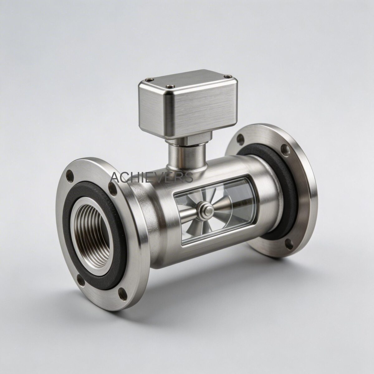
The principle of operation for Turbine Flow Meters relies on the extraction of kinetic energy from the flowing fluid. As liquid enters the meter, it is conditioned by a straightening section. These internal vanes remove undesired swirl and asymmetric velocity profiles before the fluid impacts the rotor. The dynamic forces of the fluid cause the multi-bladed turbine wheel—mounted on a high-precision, low-friction shaft—to rotate at an angular velocity directly proportional to the fluid velocity.
Because fluids like diesel and furnace oil are non-conductive, technologies like Electromagnetic Flow Meters cannot be used, making the turbine mechanism the industry standard for these hydrocarbons.
The divergence in technology occurs at the output stage:
Mechanical Counter Variants:
The rotating turbine wheel drives an index head via a physical gear train and magnetic coupling. The angular rotation is stepped down through gears to physically turn an 8-digit mechanical counter. This provides a direct, visual readout of cumulative volume without the need for external power.
Electronic / RS485 Output Variants:
Instead of a gear train, a proximity sensor (magnetic pickoff coil) detects the passing of each helical blade. Each pass generates a pulse. The local electronics process these pulses using a device-specific K-factor.
Engineering Calibration Note: The K-Factor
The relationship between rotor rotation and fluid volume is expressed by the K-factor.
Formula: K = N / V
Where:
- K = Pulses per unit volume (e.g., pulses/liter)
- N = Total number of pulses generated
- V = True volume measured via a reference prover
In electronic variants, this K-factor is programmed into the microprocessor to convert raw frequency into instantaneous flow rate (L/H) and cumulative volume (m3). The data is then transmitted via analog (4-20mA), pulse (NPN open connector), or digital RS485 Modbus protocols to the plant's central control system.
2. Head-to-Head Specification Comparison
When specifying equipment for an industrial application, understanding the exact material, pressure, and electrical ratings is paramount. Below is a comparative technical matrix based on standard Achivers brand industrial models (CE-TFS series).
| Specification / Parameter | Mechanical Counter Variant | Electronic (Pulse / 4-20mA / RS485) Variant |
| :— | :— | :— |
| Enclosure Material | S.S-304 / S.S-316 | S.S-304 / S.S-316 |
| Rotor & Shaft Material | S.S-304 / 316 Rotor; Hard SS-316 Shaft with Carbon Bush | S.S-304 / 316 Rotor; Hard SS-316 Shaft with Carbon Bush |
| Accuracy Standard | +/- 1% FSD | +/- 0.5% or 1% FSD |
| Repeatability | 0.1% | 0.1% |
| Max Working Pressure | Up to 6 Mpa (60 Bar) | Up to 6 Mpa (60 Bar) |
| Temperature Rating | -20 to 120 °C | -20 to 120 °C (Heat sinks required for electronics >80°C) |
| Power Requirement | None (Fluid kinetic energy drives gears) | 12V/24V DC or 3.3V 10AH Lithium Battery (5+ years life) |
| Output Signals | Visual dial only (8-digit cumulative) | LCD Display, NPN Pulse, 4-20mA, RS485 Modbus RTU |
| Data Protection | Inherent mechanical memory | Non-volatile EEPROM (10-year power-fail protection) |
Note: Models range from the CE-TFS-004 (4mm line size, 40~400 L/H) up to the massive CE-TFS-150 (150mm line size, handling up to 8,00,000 L/H).
3. Application Comparison Table
Different plant zones demand different instrumentation architectures. Use this decision matrix to evaluate which technology fits specific Indian industrial scenarios.
| Application Scenario | Recommended Option | Engineering Reasoning |
| :— | :— | :— |
| Remote DG Set Fuel Tank Monitoring | Battery Operated LCD / Mechanical | Grid power is unreliable; battery units operate 5+ years, while mechanical requires zero power. |
| Centralized Boiler Fuel Feed | RS485 Modbus Output | Requires real-time mass/volume flow data fed into the SCADA for combustion efficiency optimization. |
| High Viscosity Furnace Oil Lines | Alternative Tech Needed | Turbines lose linear accuracy above 50 cSt. Use Positive Displacement Flow Meters instead. |
| High Vibration Heavy Earth Moving Machinery | Mechanical Counter | Gear trains are generally less susceptible to high-frequency micro-vibrations than sensitive PCB pickoffs unless heavily potted. |
| Multi-line Batch Blending (Chemicals) | Pulse / NPN Open Connector | High-speed batch controllers require instantaneous raw pulse data rather than polled Modbus data for millisecond shutoff accuracy. |
| Hazardous Area (Zone 1/Zone 2) | Mechanical | Intrinsically safe. Electronic versions require expensive PESO/ATEX certified flameproof (Ex-d) enclosures. |
| VFD-Heavy Pumping Stations | RS485 Modbus RTU | Analog 4-20mA signals can suffer from EMI noise generated by VFDs. RS485 digital differential signals reject common-mode noise. |
| Monsoon Exposed Outdoor Manifolds | Mechanical (IP68) | Intense Indian monsoons cause water ingress in standard electronic enclosures. Mechanical registers with sealed magnetic couplings cannot short-circuit. |
4. Total Cost Comparison
Procurement heads must look beyond the initial capital expenditure (CAPEX) and evaluate the total cost of ownership (TCO) across a typical 5 to 10-year lifecycle in an Indian facility.
| Option Variant | Estimated Purchase Range (INR)* | Annual Maintenance Cost | Expected Life | Best Suited For |
| :— | :— | :— | :— | :— |
| Mechanical (Small Line <25mm) | ₹18,000 – ₹35,000 | ₹2,000 (Gear lubrication, calibration) | 5-7 Years | Basic fuel transfer, mobile bowsers |
| Mechanical (Large Line >80mm) | ₹65,000 – ₹1,50,000 | ₹4,000 (Bearing inspection) | 5-7 Years | Terminal loading, gravity decanting |
| Electronic / Pulse Output | ₹25,000 – ₹80,000 | ₹1,500 (Sensor check, cleaning) | 7-10 Years | Standard PLC integration |
| RS485 / Modbus RTU Variant | ₹35,000 – ₹2,50,000 | ₹1,000 (Software validation only) | 8-10 Years | Full SCADA, Industry 4.0 automation |
(Note: Pricing is highly dependent on precise material selection (SS304 vs SS316), line size, and specific calibration certifications required by the Legal Metrology Department).
5. Decision Guide: Which One for Your Plant?
When you are signing off on an instrumentation P.O., consider these 8 critical field scenarios:
- Power Quality and Availability: If your site suffers from frequent brownouts, voltage dips, or you lack dedicated UPS power at the piping manifold, a battery-operated LCD variant or a pure mechanical counter is mandatory to prevent data loss. The CE-TFS series offers 3.3V 10AH lithium batteries lasting over 5 years.
- Plant Automation Maturity: If your facility utilizes a central DCS (Distributed Control System) or Siemens/Allen-Bradley PLCs, the RS485 output is the logical choice. It allows you to read totalized flow, instantaneous flow, and diagnostic parameters over a single two-wire daisy chain, drastically reducing cabling costs compared to running individual 4-20mA cables.
- Custody Transfer and Legal Metrology: For buying or selling fuel (e.g., decanting from tanker trucks), Indian Legal Metrology requires high accuracy and tamper-evident sealing. Electronic variants with password-protected K-factors and dual-pulse verification offer higher security against fuel pilferage than mechanical dials, which can sometimes be mechanically manipulated or "rolled back".
- Maintenance Infrastructure: Mechanical gear trains wear out. The carbon bush and hard SS-316 shaft endure friction. If your plant lacks skilled instrumentation technicians for frequent tear-downs, pickoff-sensor electronic meters have fewer moving parts (only the rotor spins) and therefore a longer Mean Time Between Failures (MTBF).
- Fluid Contamination: Indian diesel often contains suspended particulate matter or rust from old storage tanks. While strainers are mandatory for all Turbine Flow Meters, heavy contamination will jam a mechanical gear train faster than it will break an electronic rotor.
- Operating Temperature Profile: For high-temperature boiler feed water or hot furnace oil (approaching 120°C), local LCD displays can black out or fail. In these scenarios, use a blind pickoff sensor with a remote-mounted transmitter, or stick to a heat-resistant mechanical register.
- Signal Transmission Distance: If the control room is 500 meters away from the pump house, 4-20mA signals may suffer from loop resistance drops, and mechanical meters are useless for remote viewing. RS485 Modbus can reliably transmit data up to 1,200 meters without a repeater.
- Budget Allocation: For a simple pipeline where an operator manually writes down the reading on a clipboard once a shift, spending ₹50,000 on an RS485 meter plus integration programming is engineering overkill. A sturdy mechanical flow meter is perfectly sufficient.

6. Field Calibration & RS485 PLC Integration Procedure
For engineers opting for the electronic RS485 variant, physical installation is only half the battle. Proper integration into the plant's PLC requires strict adherence to protocol. Follow this 6-step procedure for flawless commissioning:
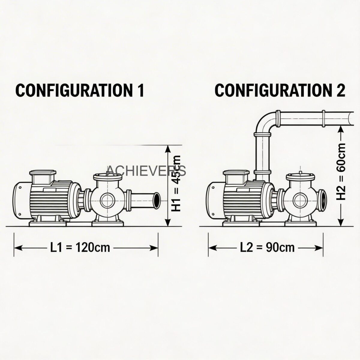
- Verify Straight Pipe Runs: Install the flow meter with a minimum of 10D (ten times the pipe diameter) of straight pipe upstream and 5D downstream. This ensures the fluid flow profile is fully developed, maximizing the straightening vanes' effectiveness and ensuring the +/- 0.5% accuracy.
- Install Upstream Filtration: Install a Y-strainer (usually 40 to 60 mesh for diesel) immediately before the upstream straight pipe section to protect the SS-316 rotor blades from weld slag and particulate damage.
- Establish Proper Grounding: Connect the SS-304/316 enclosure to the plant's instrumentation earth grid (resistance < 1 ohm). RS485 networks are highly susceptible to common-mode voltage differences; proper grounding prevents communication chip failure.
- Wire the RS485 Network: Use shielded, twisted-pair instrumentation cable (e.g., Belden 9841). Daisy-chain the connections (A to A, B to B) from the meter's output terminals to the PLC. Install a 120-ohm termination resistor at the last meter on the line to prevent signal reflection.
- Configure Modbus Parameters: Power up the meter (24V DC). Access the local display to set the Modbus Slave ID (e.g., 01), Baud Rate (commonly 9600 or 19200), Parity (None/Even/Odd), and Stop Bits. Ensure these exactly match the PLC's master port configuration.
- Map Registers and Validate Flow: In the PLC software, map the holding registers (usually 4xxxx series) to read Instantaneous Flow (floating point) and Totalized Flow (double integer). Run a known volume of fluid (e.g., using a calibrated proving tank) to verify that the physical volume matches the PLC readout. Adjust the internal K-factor if a deviation exists.
FAQ
Q: Can a mechanical turbine flow meter be upgraded to an RS485 output later?
A: Typically, no. The internal housing of a mechanical meter is machined to accommodate a magnetic coupling and gear train. Electronic meters use a threaded port for a proximity sensor. It is more cost-effective to purchase the correct variant initially.
Q: Will voltage fluctuations in my plant damage the electronic meter?
A: Standard industrial electronic meters require a stable 12V or 24V DC supply. If your plant's SMPS drops voltage frequently, the NPN pulse or 4-20mA output will become erratic. Always power these instruments through a dedicated UPS or use the 3.3V lithium battery-operated variant for standalone logging.
Q: How often should I calibrate my flow meter handling industrial diesel?
A: In Indian conditions, particulate wear on the carbon bush and SS-316 shaft can subtly shift the K-factor over time. For critical batching or custody transfer, recalibration every 12 months is recommended. For general inventory monitoring, every 24 to 36 months suffices.
Q: Why does my RS485 meter show flow when the pump is off?
A: This is usually caused by pipeline vibration turning the highly sensitive low-friction rotor, or by EMI noise inducing phantom pulses in unshielded cables. Ensure cables are shielded and separated from high-voltage motor wires, and install a check valve to prevent fluid backflow.
Q: Can I use this turbine meter for high-viscosity furnace oil (FO)?
A: Standard turbine flow meters are calibrated for low-viscosity fluids (up to approx 10-50 cSt). Thick furnace oil at ambient Indian temperatures will cause viscous drag on the rotor, destroying accuracy. You must either pre-heat the FO to lower its viscosity or switch to a Positive Displacement meter.
Q: Is PESO certification required for measuring diesel?
A: While diesel has a higher flash point than petrol, if the flow meter is installed in a designated hazardous area (Zone 1 or 2) within a refinery, chemical plant, or enclosed pump house, Indian regulations mandate PESO-approved flameproof (Ex-d) enclosures for all electronic variants. Mechanical meters are inherently safe.
Q: Does hard water scaling affect the meter's accuracy?
A: Yes. If used for utility water, calcium and magnesium deposits will build up on the helical blades, changing their aerodynamic profile and altering the K-factor. Regular cleaning schedules and upstream water softening are highly recommended.
Choosing the right instrumentation is the foundation of plant efficiency and accurate inventory control. If you require expert assistance in sizing the correct line diameter, selecting between mechanical and RS485 outputs, or integrating a flow meter into your existing PLC infrastructure, reach out to our engineering team. Provide your target fluid, maximum flow rate (L/H), operating pressure, and site conditions, and we will configure the precise Turbine Flow Meter for your application.