
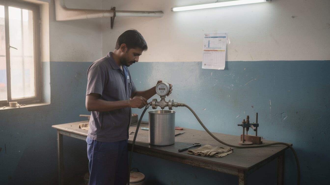
How does the CE-110 turn moving diesel into litres? It counts measuring-element cycles and applies a calibrated volume per cycle to calculate the total.
How does a positive-displacement meter measure diesel?
A positive-displacement meter measures diesel by letting each bounded portion of fuel move a measuring element. Fuel enters, advances the element, and leaves through the outlet. Each completed measuring cycle represents another portion of fuel passed.
The CE-110 positive-displacement diesel flow meter uses this principle. Its display presents the measurement result. It does not change how the fuel moves the element.
Conceptual diagram — measurement principle, not a specific model’s internal construction:
`Inlet → measured fuel pocket → moving element → outlet` ` ↓` ` counted cycles → volume total`
A pocket must stay bounded long enough for its movement to represent a repeatable volume. Fuel that leaks past the measuring element without moving it is called slip. Slip affects the relation between counted cycles and delivered litres, so the meter needs checking under the intended fluid and flow conditions.
How does fuel movement become a volume reading?
Fuel movement becomes a volume reading when the meter applies a calibrated volume per counted cycle. The basic relation is:
Measured volume (L) = counted cycles × calibrated volume per cycle (L/cycle).
Twice the counted cycles gives twice the indicated volume, if the calibration factor stays unchanged. That factor comes from calibration. Pocket size alone does not account for slip.
A rate display works the same way, using volume change over time: flow rate (LPM) = change in volume (L) ÷ elapsed time (min). Positive displacement counts volume directly. Other principles sense a different physical effect first, then infer volume.
| Measurement parameter | Positive displacement | Coriolis | Vortex | Electromagnetic |
|---|---|---|---|---|
| Primary effect | Repeated displaced volumes | Coriolis force in vibrating tubes | Vortices shed behind a bluff body | Voltage induced as conductive fluid crosses a magnetic field |
| Primary measured quantity | Volume | Mass flow | Shedding frequency | Fluid velocity |
| Route to volume | Count cycles and apply calibration | Use mass flow and fluid density | Apply a calibrated frequency-to-flow relation | Apply velocity and meter cross-section |
| Moving measuring parts | Yes | Vibrating tubes | No rotating measuring element | No rotating measuring element |
| Key fluid condition | Slip depends on clearance and fluid | Fluid must pass through the vibrating tubes | Vortices must form and be detected | Fluid must conduct electricity |
These technologies are not interchangeable. Pick one only after checking the actual fluid, flow range and required reading.
How are measurement cycles shown as totals?
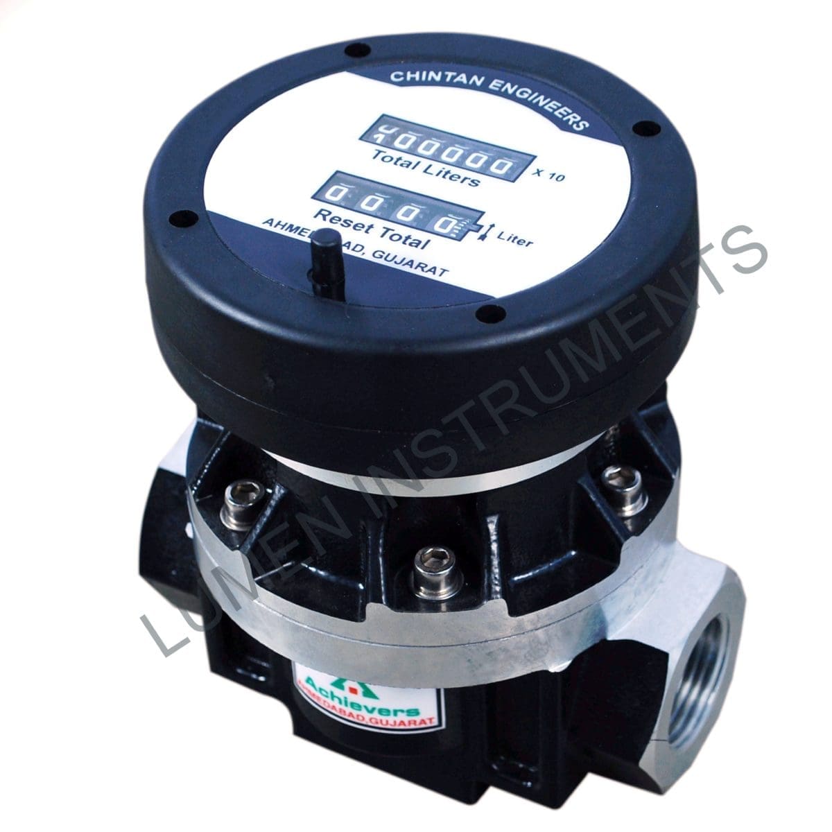
The CE-110 has a four-digit reset total and a six-digit cumulative total. Reset the first for a delivery. Use the second to track accumulated throughput.
The CE-111 and CE-119 show flow rate plus totalized flow. Both carry resettable and cumulative totals. A resettable total answers how much passed during one interval; a cumulative total tracks the running count.
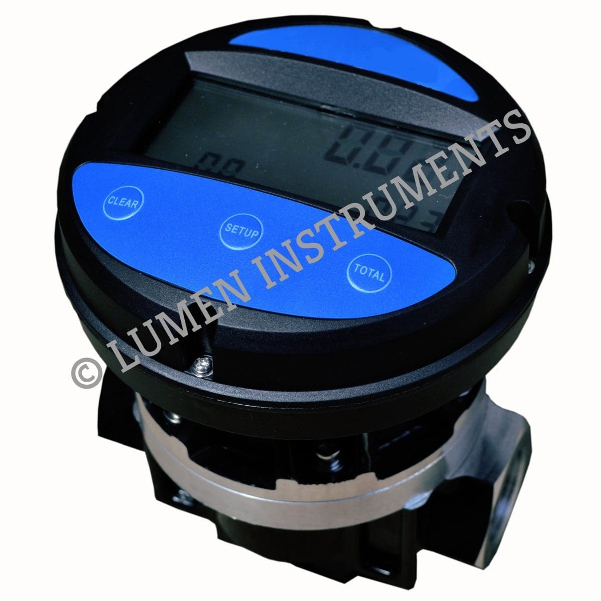
These displays report the result of measurement, not the raw cycle count itself. Confirm the display’s units and resolution before comparing its reading against a calibration measure.
What do the CE meter specifications report?
The CE-110, CE-111 and CE-118 variants have +0.5% accuracy and <0.03% repeatability. Flow range, connection size and pressure limit change with the variant. The table below keeps each model’s figures separate.
| Model | Flow range (LPM) | Connection | Accuracy | Repeatability | Max. viscosity | Max. working pressure |
|---|---|---|---|---|---|---|
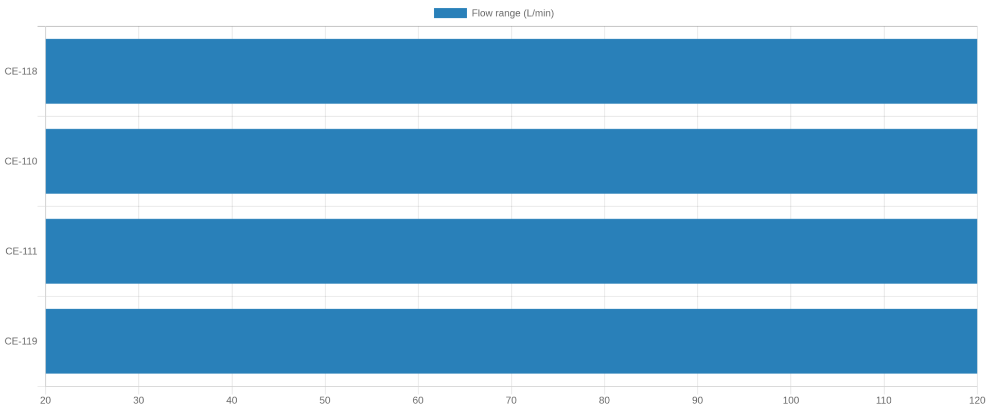
| CE-110-25 | 20–120 | 25 mm | +0.5% | <0.03% | 1 Pa·s | 3.4 MPa |
| CE-110-40 | 25–250 | 40 mm | +0.5% | <0.03% | 1 Pa·s | 1.8 MPa |
| CE-110-50 | 30–300 | 50 mm | +0.5% | <0.03% | 1 Pa·s | 1.8 MPa |
| CE-111-25 | 20–120 | 25 mm | +0.5% | <0.03% | 1 Pa·s | 3.4 MPa |
| CE-111-40 | 25–250 | 40 mm | +0.5% | <0.03% | 1 Pa·s | 1.8 MPa |
| CE-111-50 | 30–300 | 50 mm | +0.5% | <0.03% | 1 Pa·s | 1.8 MPa |
| CE-118-25 | 20–120 | 25 mm | +0.5% | <0.03% | 1 Pa·s | 3.4 MPa |
| CE-118-40 | 25–250 | 40 mm | +0.5% | <0.03% | 1 Pa·s | 1.8 MPa |
| CE-118-50 | 30–300 | 50 mm | +0.5% | <0.03% | 1 Pa·s | 1.8 MPa |
The viscosity limit of 1 Pa·s equals 1000 cP. An installation needing 110 LPM falls within all three variant ranges here.
Flow rate alone can’t settle that choice, so check connection size and working pressure too. At 260 LPM, only the -50 variant’s range extends high enough.
Accuracy and repeatability answer different questions here. The catalog’s +0.5% accuracy figure concerns closeness to a reference volume, while the <0.03% repeatability figure concerns agreement between repeated readings under the same conditions. Both figures are stated as catalog specifications, not as a guarantee under every installation or operating condition.
Repeatability of <0.03% is much tighter than the ±0.5% accuracy band. A meter can give closely repeated readings while remaining near the edge of its accuracy band. Before setting an acceptance limit, confirm the reference, flow rate and viscosity used for each figure.
For a volume check, compare the meter reading against a traceable reference volume at representative flows. Record fluid, temperature, flow rate and indicated litres for each run.
Calculate indication error (%) = 100 × (meter volume − reference volume) ÷ reference volume. Repeat the runs to assess repeatability separately from accuracy.
OIML R117 concerns measuring systems for liquids other than water and may apply to a regulated fuel-measurement requirement. ISO 4064 and OIML R49 concern water meters, so neither counts as a diesel-meter approval. Confirm the standard and approval your application actually requires.
How does engine fuel-consumption measurement differ?
An inline transfer meter totals fuel passing through one line. Engine consumption needs both supply and return volumes, because fuel returned from an engine was supplied but not used. Fuel used equals fuel supplied minus fuel returned, over the same interval.
The diesel generator and vehicle engine fuel-flow meter uses an oval-gear flow sensor. Its display shows in-flow, out-flow and fuel used in litres with time. That separates supply and return readings, instead of treating supply alone as consumption.
The engine unit’s sensor is selected by engine power rating, not by the CE inline meters’ 20–300 LPM variant ranges. Check both the line flow rate and the engine unit’s sensor rating before fitting it. The supply-and-return measurement explanation covers the netting logic in more detail.
When to use this technology
| Measurement need | Suitable starting point | Check before selection |
|---|---|---|
| One-line diesel transfer total | CE-110 or CE-111 | Flow range, connection and pressure |
| Live rate plus transfer totals | CE-111 | Required display units and calibration basis |
| Positive-displacement measurement for an oil line | CE-118 | Actual fluid, viscosity and operating range |
| Engine fuel used after return | Engine consumption meter | Supply and return measurement points |
The CE-118 positive-displacement flow meter offers the same three flow-range choices shown above. Confirm the actual fluid and operating conditions for that line; its name alone is not a compatibility test.
Frequently asked questions
What does a positive-displacement diesel flow meter count?
It counts repeated measuring-element cycles as fuel passes through the meter; those cycles are used to accumulate the measured volume.
What flow ranges are listed for the CE-110 variants?
The catalog lists 20–120lpm for CE-110-25, 25–250lpm for CE-110-40 and 30–300lpm for CE-110-50.
What totals are listed for the CE-110?
Its catalog description lists a four-digit reset total and a six-digit cumulative total.
What does the diesel engine fuel-consumption meter display?
It displays fuel flowing in, fuel returning and fuel used in liters with time.
Quick pick
- Choose CE-110 for a four-digit reset total and six-digit cumulative total.
- Choose CE-111 when the operator also needs a flow-rate display.
- Choose -25 for 20–120 LPM, -40 for 25–250 LPM, or -50 for 30–300 LPM, then check pressure and connection.
- Choose the engine consumption meter if the reading must subtract returned fuel from supplied fuel.