
Accurate fluid measurement in industrial environments is not merely a matter of installing a sensor in a pipe; it is an exercise in fluid dynamics, mechanical precision, and signal integrity. For Indian plant managers and instrumentation engineers dealing with costly utilities like furnace oil, high-speed diesel (HSD), and raw water, understanding the underlying physics of measurement technology is critical. Procurement decisions ranging from ₹20,000 to ₹10,00,000 hinge on matching the right physical measurement principle to the specific fluid dynamics of the site.
Among the various technologies available, Turbine Flow Meters remain one of the most reliable, high-precision instruments for clean, non-acidic liquids. However, achieving their rated accuracy—often up to 0.5% or 1% Full Scale Deflection (FSD)—requires a deep understanding of rotor dynamics, flow conditioning, and K-factor linearization. This technical deep dive explains exactly how these meters operate, how to interpret their specifications, and how to deploy them successfully in the demanding operating conditions typical of Indian industrial sites, from petrochemical refineries to large-scale pharmaceutical plants.
1. Working Principle: How Turbine Flow Meters Operate
At its core, a Turbine Flow Meters is a velocity-based measurement device. The operation relies on extracting kinetic energy from the flowing fluid to drive a mechanical rotor. When a liquid such as diesel or furnace oil enters the meter housing, it is first conditioned by the straightening section.
Indian pipelines, especially those retrofitted into existing factory layouts, often suffer from poor piping geometry, creating swirl, turbulence, and asymmetrical velocity profiles. The internal straightening vanes act as flow conditioners, breaking down these large turbulent eddies and flattening the velocity profile before the fluid impacts the rotor. This ensures that the dynamic forces of the flowing fluid hit the turbine blades uniformly.
Once conditioned, the accelerated liquid encounters the turbine wheel. This wheel is mounted on a main shaft supported by high-precision, low-friction bearings. The turbine features helical blades machined at a specific, known angle relative to the fluid flow vector. The fluid imparts a driving torque on these blades, causing the rotor to spin. The angular velocity of the turbine wheel becomes directly proportional to the fluid velocity.
Mathematically, the relationship is governed by the flow equation:
Volumetric Flow Rate (Q) = Velocity (V) x Cross-sectional Area (A)
Because the cross-sectional area of the meter is constant, the rotor's rotational speed (RPM) is directly proportional to the volumetric flow rate.
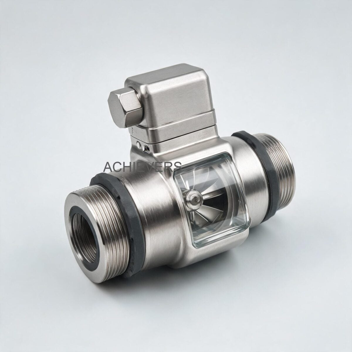
To translate this mechanical rotation into actionable data, the meter employs a pickoff sensor. Most modern Turbine Flow Meters use a magnetic proximity probe or variable reluctance sensor. As each ferromagnetic turbine blade passes through the magnetic field of the pickoff coil, it disturbs the flux lines, generating a sinusoidal alternating current (AC) voltage pulse.
The frequency of these pulses is directly proportional to the flow rate. By accumulating these pulses over time, the total volumetric flow is calculated. The critical calibration parameter here is the K-Factor, defined as the number of pulses generated per unit volume of fluid passed (e.g., Pulses per Liter).
Engineering Formula for Pulse-to-Volume Conversion:
Frequency (Hz) = (K-factor * Volumetric Flow Rate) / 3600
Where Flow Rate is in Liters per Hour (L/H) and K-factor is in Pulses per Liter.
2. Complete Technical Specifications
Selecting the correct meter requires matching the instrument's materials and electrical characteristics to the process fluid and site infrastructure. The data below reflects the exact engineering specifications for Lumen Instruments' (Achivers brand) series of turbine meters.
| Parameter | Specification | Engineering Notes |
| :— | :— | :— |
| Enclosure Material | S.S-304 / S.S-316 | Provides excellent corrosion resistance for outdoor Indian site conditions. |
| Rotor Material | S.S-304 / S.S-316 | Resists deformation under high flow velocity and dynamic fluid forces. |
| Shaft Material | Hard Stainless Steel-316 | Outfitted with a carbon bush for low-friction rotation and extended bearing life. |
| Accuracy | +/- 0.5% or 1% FSD | Valid in standard installation positions with fully developed flow profiles. |
| Repeatability | 0.1% | Highly stable for batching operations in pharma and chemical dosing. |
| Maximum Working Pressure | 6 Mpa (approx. 60 Bar) | Suitable for high-pressure transfer lines and heavy oil pumping stations. |
| Fluid & Ambient Temp. | -20 to 120 °C | Easily handles heated furnace oil applications and intense Indian summer ambient heat. |
| Pulse Output Power | 12 V DC | Standard low-voltage requirement for safe industrial environments. |
| Pulse Output Signal | NPN open connector | High level > 8 VDC; Low level < 0.8 VDC. Compatible with most PLCs. |
| Connections | Thread (M/F) or Flange | Flange preferred for larger lines (above 50mm) to prevent leakages. |
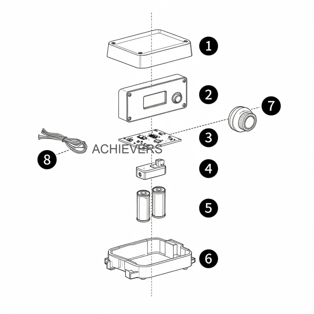
| Battery Operated Option | 3.3 V 10AH Lithium Battery | Dual row LCD display. Battery lasts over 5 years. Power-fail protection retains 10-year total flow data. |
| Analog Output Option | 4 to 20 mA (24 V DC power) | Ideal for long-distance signal transmission to SCADA systems without voltage drop. |
Model-Wise Technical Flow Range Data:
| Model Number | Line Size (mm) | Flow Range (Liters / Hour) |
| :— | :— | :— |
| CE-TFS-004 | 04 MM | 40 ~ 400 L/H |
| CE-TFS-012 | 12 MM | 600 ~ 6,000 L/H |
| CE-TFS-025 | 25 MM | 1,000 ~ 10,000 L/H |
| CE-TFS-040 | 40 MM | 2,000 ~ 20,000 L/H |
| CE-TFS-050 | 50 MM | 4,000 ~ 40,000 L/H |
| CE-TFS-080 | 80 MM | 10,000 ~ 100,000 L/H |
| CE-TFS-100 | 100 MM | 20,000 ~ 200,000 L/H |
| CE-TFS-150 | 150 MM | 30,000 ~ 300,000 L/H |
| CE-TFS-150 (High Cap) | 150 MM | 80,000 ~ 800,000 L/H |
3. Technology Comparison & Decision Matrix
No single flow meter is universal. While turbine technology excels in low-viscosity, clean fluids, it is essential to compare it against other dominant technologies like Electromagnetic Flow Meters and Positive Displacement Flow Meters to make an informed procurement decision.
Technology Comparison Table
| Evaluation Parameter | Turbine Flow Meter | Electromagnetic Meter | Positive Displacement |
| :— | :— | :— | :— |
| Measurement Principle | Fluid velocity driving a rotor | Faraday’s Law of Induction | Trapping discrete fluid volumes |
| Fluid Conductivity | Not required (works on oils/fuels) | Required (> 5 microSiemens/cm) | Not required |
| Viscosity Tolerance | Best for low to medium viscosity | Independent of viscosity | Excellent for high viscosity |
| Pressure Drop | Moderate (due to rotor/vanes) | Zero (unobstructed flow tube) | High (due to tight internal clearances) |
| Accuracy Profile | Very high (up to 0.5%) | High (up to 0.5%) | Extremely high (up to 0.1%) |
| Particulate Tolerance | Low (requires Y-strainer/filter) | High (can handle slurries) | Low (gears can jam) |
| Cost to Scale | Highly economical at large sizes | Moderate to high | Very expensive for large line sizes |
"When to Use This Technology" Decision Matrix:
- Use Turbine Meters When: You are measuring clean hydrocarbons (diesel, furnace oil, petrol), raw cooling water, or low-viscosity non-acidic chemicals. You need high accuracy at a moderate cost, especially in line sizes from 25mm to 150mm. They are the standard for diesel dispenser integration.
- Use Electromagnetic Meters When: You are measuring conductive liquids like wastewater, sewage, acids, or slurries. Never use mag meters for diesel or oils, as hydrocarbons lack the necessary electrical conductivity.
- Use Positive Displacement Meters When: You are dealing with highly viscous fluids (heavy gear oils, molasses, resins) where the viscosity would severely shift the K-factor of a turbine meter, or when you need custody-transfer level accuracy (0.1%) and possess the budget for it.
4. Performance Characteristics and Error Sources
Understanding the internal dynamics of turbine meters is crucial for preventing measurement errors. The accuracy of this instrument relies heavily on a stable Reynolds number.
Kinematic Viscosity and the K-Factor Shift
The K-factor is not perfectly linear across all flow rates. At very low flow rates, the driving torque is minimal, and the mechanical drag torque from the carbon bush bearings has a disproportionate effect, causing the rotor to under-register. Furthermore, if the fluid's kinematic viscosity changes due to temperature fluctuations—common with furnace oil in Indian winter mornings versus summer afternoons—the boundary layer thickness on the turbine blades changes. High viscosity creates a drag effect that shifts the calibration curve. For highly viscous heavy oils, the meter must be specifically factory-calibrated at the operating viscosity.
Signal Integrity and Power Quality
Indian industrial environments are notorious for severe voltage fluctuations and heavy electromagnetic interference (EMI) from Variable Frequency Drives (VFDs) and large induction motors. The 12 V DC NPN open collector output or the 4 to 20 mA (24 V DC) analog output must be shielded. For digital data acquisition, these meters integrate well with RS485 communication standards. RS485 uses differential signaling over twisted pair cables, meaning it effectively cancels out the ambient electrical noise common in Indian factories, ensuring the pulse count reaching the PLC or batch controller is exactly what the pickoff sensor generated.
Air Entrainment and Cavitation
Because turbine meters measure velocity, any air or vapor bubbles mixed with the liquid will spin the rotor faster, causing over-registration (charging you for air instead of fuel). In high-temperature installations (approaching the 120 °C limit), a drop in pipeline pressure can cause the liquid to flash into vapor (cavitation). This not only destroys accuracy but can mechanically shatter the SS-316 rotor blades. Backpressure valves and air eliminators are essential in such setups.
5. Materials, Chemical Compatibility & Installation Procedure
The structural integrity of these meters relies on SS-304 and SS-316 stainless steel. These alloys offer immense tensile strength and excellent resistance to pitting and oxidation. The shaft utilizes hard SS-316 with a carbon bush, providing self-lubricating properties which are essential when measuring non-lubricating fluids like water, while holding up perfectly under the lubricating nature of heavy oils.
Fluid Compatibility Table
| Process Fluid | Compatible? | Engineering Notes |
| :— | :— | :— |
| High Speed Diesel (HSD) | Yes | Excellent performance. Fluid naturally lubricates the carbon bush. |
| Furnace Oil (FO) | Yes | Ensure temperature is high enough to reduce viscosity into the linear flow range. |
| Light Diesel Oil (LDO) | Yes | Ideal application. Highly repeatable measurement. |
| DM Water / Raw Water | Yes | SS-316 enclosure prevents rusting. Carbon bush handles lack of lubrication. |
| Sulfuric / Nitric Acid | No | Corrosive action will destroy the internals. Use Mag meters or specialized alloys. |
| Edible Oils | Yes | SS-304/316 is food grade. Excellent for food processing batching. |
| Mining Slurries | No | Abrasive particulates will destroy the rotor blades and jam the bearings instantly. |
| Alcohols / Solvents | Yes | Highly compatible, but requires PESO-certified explosion-proof electronics. |
Standard Installation Procedure for Maximum Accuracy:
Turbine meters are sensitive to flow profile distortions. Adhering to strict piping geometry is mandatory.
- Isolate and Depressurize: Ensure the pipeline is completely depressurized and locked out before cutting into the line.
- Install Upstream Straight Run: Install a minimum of 10 times the nominal pipe diameter (10D) of straight, unobstructed pipe upstream of the meter. Do not install elbows, valves, or T-joints in this section.
- Install Downstream Straight Run: Install a minimum of 5 times the pipe diameter (5D) of straight pipe downstream of the meter to prevent flow separation and back-eddies.
- Fit a Y-Strainer / Filter: Install a high-quality strainer (typically 40 to 100 mesh, depending on the fluid) before the 10D upstream run. Indian diesel often contains suspended rust and particulates from transport tankers that will jam the tight clearances of the turbine rotor.
- Align Flanges: Carefully align the meter flanges with the pipe flanges. The internal bore must match exactly. Any gasket protruding into the fluid stream will create severe turbulence and destroy the meter's accuracy.
- Electrical Grounding: Connect the SS-304/316 enclosure to the plant earth grid. Run the 12V DC power and NPN output signal cables in dedicated, shielded metal conduits away from high-voltage AC cables to prevent induced EMF noise.
- Purge the Line: Slowly open the upstream valve to fill the line. Do not subject the meter to a sudden burst of pressurized air (air shock), which can spin the rotor past its maximum RPM limit and shatter the carbon bush.
6. Calibration, Verification, and Certification
Before a turbine meter leaves the factory, it undergoes a wet calibration process on a gravimetric or volumetric proving rig. Water or a calibration fluid is pumped through the meter at varying flow rates across its specified range (e.g., from 2,000 L/H to 20,000 L/H for the CE-TFS-040). The actual volume collected is compared against the pulses generated to establish the unique K-factor.
For Indian applications, especially in custody transfer (buying or selling fuel) or tax-related fuel consumption logging, meters may need to comply with the Legal Metrology Act of India. While internal process meters don't strictly require Legal Metrology stamping, having a meter calibrated to standard reference norms (like those set by BIS or OIML) ensures that internal audits and mass-balance equations in chemical plants tally correctly.
Furthermore, when utilized in hazardous areas—such as transferring ethanol, petrol, or aviation turbine fuel—the electrical components (the pickoff sensor and digital display enclosure) must hold PESO (Petroleum and Explosives Safety Organisation) certification to ensure intrinsically safe or flameproof operation.
The lithium battery-operated variant (3.3 V 10AH) is incredibly popular in remote Indian mining or construction sites where reliable grid power is unavailable. The fact that it stores the cumulative flow values and instrument coefficients for ten years in non-volatile memory ensures that sudden battery failures do not result in the loss of critical production data.
FAQ
Q: Why is my turbine flow meter reading higher than the actual volume delivered?
A: Over-registration is almost always caused by air or vapor entrained in the liquid. Because air has a much lower density than liquid, it passes through the meter at a higher velocity, spinning the rotor faster. Ensure you have an air eliminator installed upstream.
Q: Can I use a turbine flow meter for highly viscous liquids like cold furnace oil?
A: It is not recommended unless the oil is heated. High viscosity drastically increases the drag on the rotor blades, which causes the meter to under-register and pushes the K-factor out of its linear range. For cold, heavy oils, positive displacement meters are superior.
Q: How often should I clean the upstream filter?
A: In Indian industrial conditions, especially with diesel received from road tankers, the Y-strainer should be checked and cleaned weekly during the first month of operation to gauge the contamination level, and then integrated into a monthly preventive maintenance schedule.
Q: What is the significance of the 10D and 5D straight piping rule?
A: 10 pipe diameters upstream and 5 pipe diameters downstream allow the fluid's velocity profile to stabilize into a fully developed, symmetrical shape. If a valve or elbow is too close to the meter, it causes swirl, making the fluid strike the turbine blades at an incorrect angle, destroying accuracy.
Q: How long does the battery last on the standalone display model?
A: The integrated 3.3 V 10AH lithium battery is designed to last more than 5 years continuously, owing to the ultra-low power consumption of the dual-row LCD and the internal micro-controller.
Q: Is it safe to use this meter in hazardous areas?
A: The standard SS-316 mechanical body is safe, but the electrical pickoff sensor and display must have the appropriate explosion-proof enclosure and PESO certification if you are using it in Zone 1 or Zone 2 hazardous areas involving flammable gases or vapors.
Q: How is the RS485 signal better than the 4-20mA output?
A: While 4-20mA is excellent for resisting voltage drops over long distances, RS485 allows for digital, multi-drop communication. It can transmit not just the flow rate, but also diagnostic data, totalized volume, and K-factor settings directly to a PLC over a noisy factory network without signal degradation.
To ensure you select the correct instrumentation for your specific fluid dynamics, pressure drops, and electrical infrastructure, professional engineering support is paramount. Contact our technical sales team today with your process fluid details, line size, maximum flow rate, and operating temperature to get a customized quotation for Turbine Flow Meters designed explicitly for your site conditions.