
Selecting the appropriate flow measurement technology for industrial fuel transfer is a critical engineering decision that directly impacts operational expenditure (OPEX) and inventory control. When dealing with large volumes of high-speed diesel (HSD), marine diesel, or heavy fuel oils, even a 1% measurement error translates to massive financial discrepancies over an annual operating cycle. For plant managers, instrumentation engineers, and procurement heads across global markets—from remote mining outposts to offshore platforms—relying on underspecified or incorrectly selected measurement devices leads to premature mechanical failure, measurement disputes, and costly downtime.
This technical guide serves as a comprehensive resource for how to choose diesel flow meters for industrial fuel transfer. We will systematically evaluate the underlying physics of volumetric measurement, the impact of fluid viscosity and pressure drop, and the critical integration of mechanical and digital outputs into modern plant control systems (DCS/PLC). By mapping real-world installation constraints to specific meter internals, this guide provides the rigorous specifications-first approach required by global and diesel flow meters in India for industrial buyers to ensure long-term accuracy, minimal maintenance, and regulatory compliance.
1. What Is Diesel Flow Meters and What Does It Do
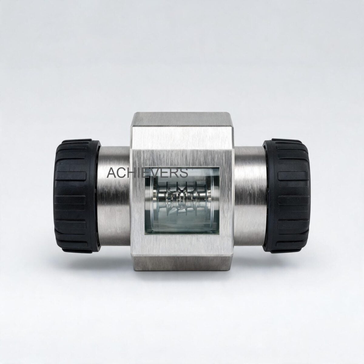
Diesel Flow Meters utilizing positive displacement (PD) technology represent the industry standard for direct volumetric flow measurement. Unlike inferential meters (such as turbine or vortex meters) that calculate flow based on fluid velocity, a positive displacement meter directly quantifies the volume of the fluid passing through the body.
The mechanism operates by repeatedly entrapping liquid within precision-machined measuring chambers. This process is conceptually similar to continuously filling and emptying a bucket of a known volume, where the number of times the bucket is emptied directly correlates to the total volumetric throughput. Entrapment is achieved using rotating mechanical parts—such as oval gears, sliding vanes, or bi-rotors—that form moving seals against the meter body.
Because these rotating parts are machined to extremely tight tolerances, they prevent fluid from bypassing the measuring chamber unmeasured—a phenomenon known as "slippage." As the fluid exerts pressure against the rotors, they turn at a speed proportional to the flow rate. This rotation is then transferred either mechanically to a local register or magnetically to a digital sensor to generate electrical pulses.
Positive Displacement Technical Specifications
The following table details the baseline parameters and operational thresholds typically associated with industrial-grade Diesel Flow Meters.
| Specification Parameter | Value / Range | Engineering Notes |
| :— | :— | :— |
| Measurement Principle | Positive Displacement (PD) | Direct volumetric measurement via rotating entrapment chambers. |
| Standard Accuracy | ± 0.2% to ± 0.5% of reading | Accuracy improves as fluid viscosity increases due to reduced slippage. |
| Operating Pressure | Up to 10 – 40 Bar (150 – 600 PSI) | Highly dependent on housing material (Cast Iron vs. Cast Steel). |
| Temperature Range | -20°C to +120°C | High-temperature applications require specific high-clearance rotors. |
| Viscosity Handling | 1 cSt to > 100,000 cSt | Ideal for diesel, HSD, and marine diesel; not recommended for dry gases. |
| Pressure Drop | < 0.5 Bar at maximum flow | Critical parameter; exceeding limits causes catastrophic bearing wear. |
| Global Approvals | ATEX, CE, ISO 9001, OIML | Required for custody transfer and hazardous area (Ex-proof) installations. |
2. Key Selection Criteria for Industrial Buyers
Specifying Diesel Flow Meters requires a thorough evaluation of the fluid dynamics and the specific environmental conditions of the installation site. Industrial buyers must navigate a matrix of variables to ensure the selected meter will perform reliably over its lifecycle.
A. Viscosity, Temperature, and Slippage Dynamics
In positive displacement measurement, viscosity is a critical asset rather than a hindrance. As fluid viscosity increases (such as transferring cold diesel or heavy fuel oils), the fluid acts as a natural seal between the rotor clearances and the meter body. This decreases "slippage" (the amount of fluid bypassing the measurement chamber), which counter-intuitively improves measurement accuracy, particularly at the lower end of the flow range. However, plant engineers must account for temperature fluctuations. Diesel fuel's kinematic viscosity changes with temperature; a meter calibrated for diesel at 40°C may exhibit a slight shift in its K-factor if operated in sub-zero environments due to increased fluid shear resistance.
Calibration Note: Ensure the working fluid matches the calibration fluid. Different amounts of slippage exhibited by different liquids can cause measurement errors if a meter calibrated on water is used to measure viscous marine diesel.
B. Pressure Drop and Bearing Wear
Positive displacement meters are driven entirely by the kinetic energy and pressure of the fluid stream. The energy required to turn the rotors generates a pressure drop (ΔP) across the meter. If an application forces high flow rates of highly viscous fluid through a relatively small meter, the resulting pressure drop will spike. An excessive pressure drop places severe mechanical strain on the rotor shafts and bearings.
Operating above the manufacturer's maximum pressure drop specification leads to premature bearing wear, degraded measurement accuracy, and eventually, catastrophic meter failure. If your pressure drop calculation exceeds 0.5 Bar (or the manufacturer's limit), you must upsize the flow meter line size, even if the flow rate falls within a smaller meter's stated capacity.
C. Upstream Filtration Requirements
Because PD meters rely on tight internal clearances (often measured in microns) to maintain accuracy, they are highly susceptible to damage from particulate contamination. Sand, rust flakes, weld slag, or other debris in dirty industrial pipes will score the internal measuring chambers, increasing the clearance gaps and causing a permanent loss of accuracy due to increased slippage. Installing an upstream Y-strainer or basket filter with the correct mesh size (typically 80 to 100 mesh for diesel) is non-negotiable.
D. Two-Phase Flow and Air Elimination
A volumetric flow meter cannot distinguish between a volume of liquid and a volume of air. If the fluid stream contains entrained air bubbles or vapor pockets—common in tank-stripping operations or poorly sealed pump suctions—the flow meter will measure the gas as if it were diesel. This results in artificially high totalization and severe financial measurement disputes. To mitigate this, an air eliminator (deaerator) must be installed upstream of the meter to vent off gases before they enter the measuring chamber.
E. Flow Rate Range and Turndown Ratio
Flow meters must be sized for the actual continuous flow rate of the process, not merely the pipe diameter. Industrial PD meters generally offer excellent turndown ratios (often 10:1 to 30:1), meaning they maintain high accuracy across a wide flow band. However, running a meter continuously at its absolute maximum rated flow will drastically reduce its operational lifespan. Best engineering practice dictates sizing the meter so that normal continuous operation falls between 50% and 70% of the meter's maximum capacity.
F. Output Signals and Control System Integration
The transition from manual logging to automated DCS/SCADA integration means you must buy diesel flow meters with pulse output and totalizer configurations that match your control architecture.
- Mechanical Registers: Ideal for remote sites without reliable power, providing a rugged, non-volatile local display.
- Pulse Outputs: Often generated via Hall Effect sensors or Reed switches, yielding high-frequency raw volumetric data for batch controllers.
- 4-20mA Analog: Best for continuous flow rate monitoring and PID loop control for dosing pumps.
- RS-485 (Modbus RTU): Essential for modern industrial networks, allowing a single cable to transmit total flow, current flow rate, and diagnostic data to the plant's central PLC.
Engineering Formula: Volumetric Flow Rate
The fundamental operation of the PD meter can be modeled by the equation:
Q = V x N x Ev
Where:
- Q = Actual volumetric flow rate
- V = Swept volume of the measuring chamber per single revolution
- N = Rotational speed of the measuring element (RPM)
- Ev = Volumetric efficiency (1 minus the slippage factor)
3. Technology Comparison and "When to Use" Matrix
No single flow measurement technology is perfect for every application. Diesel fueloilmeter.net covers an extensive breadth of technologies, allowing industrial buyers to make comparative, specification-driven choices. The table below compares Positive Displacement against other dominant technologies like Turbine Flow Meters and Electromagnetic meters.
Technology Comparison Table
| Parameter | Positive Displacement (PD) | Turbine Flow Meter | Electromagnetic (Mag) | Vortex Shedding |
| :— | :— | :— | :— | :— |
| Best Used For | Diesel, Oils, High Viscosity | Light hydrocarbons, Water | Conductive fluids, Wastewater | Steam, Gases, Low-viscosity liquids |
| Accuracy Profile | ± 0.2% (High accuracy) | ± 0.5% (Very good) | ± 0.5% (Very good) | ± 1.0% (Moderate) |
| Viscosity Effect | Accuracy improves with viscosity | Accuracy degrades at high viscosity | Unaffected (but fluid must be conductive) | Requires minimum Reynolds number |
| Pressure Drop | Moderate to High | Low to Moderate | Zero (Unobstructed pipe) | Moderate (Bluff body restricts flow) |
| Filtration Needed? | Critical (Tight clearances) | Critical (Protects turbine blades) | Not required | Not required |
| Conductivity Need | None (Works on dielectrics) | None | Must be conductive (Not for diesel) | None |
"When to Use This Technology" Decision Matrix
- Select Positive Displacement Meters when transferring highly valuable, non-conductive, viscous liquids (like diesel or lube oils) where maximum volumetric accuracy is required for custody transfer or precise batching.
- Select Turbine Meters when measuring large volumes of clean, low-viscosity fluids (like light naphtha or water) where a lower pressure drop is required and the budget is tighter.
- Select Electromagnetic Meters ONLY for conductive liquids (water, slurries, chemicals). Never specify a Mag meter for diesel fuel, as hydrocarbons act as electrical insulators and cannot be measured by Faraday's Law of Induction.
- Select Vortex Meters when measuring utility steam or compressed air, where wide temperature variations occur, and pressure drop is acceptable.
Product Variant Comparison
For buyers reviewing the specific diesel flow meters supplier for manufacturers inventory, understanding the exact variant capabilities prevents under-specifying. Below is a breakdown of the Achievers brand line of industrial meters.
| Model / Variant | Core Display Type | Key Output Capabilities | Best For Application |
| :— | :— | :— | :— |
| Achievers CE-113 | Mechanical Register | Local mechanical display only, no power needed. | Remote bulk storage, mobile bowsers, off-grid dispensing. |
| Achievers CE-110 | Basic Digital | Local LCD, battery operated. | Upgrading mechanical systems to digital readability. |
| Achievers CE-111 | Advanced Digital | Digital LCD with improved batch totalization. | Standard indoor industrial transfer and generator feeding. |
| Achievers CE-112 | Smart Digital Transmitter | 4-20 mA, Pulse Output, RS-485 Modbus. | DCS/SCADA integration, automated liquid batching systems. |
4. Common Mistakes Industrial Buyers Make When Choosing
Procurement teams frequently attempt to cut capital expenditure by ignoring seemingly minor specifications, only to face massive operational costs down the line. Avoid these critical engineering errors:
- Sizing the Meter by Pipe Diameter Instead of Flow Range
- The Mistake: Ordering a 3-inch meter simply because the existing pipeline is 3 inches, without checking actual pump flow rates.
- The Consequence: If the normal flow rate is only at 10% of the 3-inch meter's capacity, the meter will suffer from high relative slippage, resulting in poor accuracy. Always size the meter based on the actual flow rate, using reducers/expanders if necessary.
- Omitting the Upstream Air Eliminator
- The Mistake: Pumping fuel directly from an underground tank without gas separation.
- The Consequence: As pumps strip tanks, air is drawn in. The flow meter registers air bubbles as fuel. The buyer pays for "phantom" diesel, leading to severe inventory reconciliation failures at the end of the month.
- Bypassing Proper Filtration
- The Mistake: Assuming fuel is "clean enough" and skipping the Y-strainer to save on pressure drop or capital cost.
- The Consequence: Pipe scale, rust, or sand gets trapped between the meter's rotors and the casing wall. This scores the metal, permanently ruining the internal tolerances. The meter loses its accuracy and requires a complete factory rebuild.
- Ignoring Pressure Drop Constraints on Viscous Fluids
- The Mistake: Failing to calculate the total system pressure drop when measuring thicker fuels in cold temperatures.
- The Consequence: The extreme back-pressure forces the meter's rotors against their bearings with massive hydraulic force. Bearings burn out prematurely, locking up the meter and halting the entire transfer process.
- Specifying Incompatible Elastomer Seals
- The Mistake: Ordering standard EPDM or Nitrile O-rings without verifying chemical compatibility with modern biodiesel blends (which can be highly aggressive).
- The Consequence: The seals swell, degrade, or dissolve, leading to hazardous external fuel leaks and immediate environmental compliance violations. Viton (FKM) or PTFE seals must be specified for complex fuel blends.
5. Enquiry Specification Checklist
To streamline the procurement process and ensure you receive the correct instrumentation from your manufacturer, utilize this diesel flow meters specifications checklist when generating your Request for Quotation (RFQ). Providing this exact data guarantees a chemically compatible, accurately sized meter.
- Fluid Composition: Specify the exact fluid (e.g., High-Speed Diesel, Marine Diesel, Biodiesel B20, Lube Oil). Include any known chemical additives.
- Operating Viscosity: Provide the kinematic viscosity (in cSt) at the normal operating temperature.
- Flow Rate Parameters: Detail the Minimum, Normal (Continuous), and Maximum peak flow rates in Liters Per Minute (LPM) or Cubic Meters per Hour (m³/hr).
- Temperature Range: State both the fluid temperature and the ambient environmental temperature (crucial for outdoor or extreme climate installations).
- Operating Pressure: Provide the normal system pressure and the maximum allowable design pressure (to determine flange ratings like ANSI 150# or PN16).
- Maximum Allowable Pressure Drop (ΔP): Specify how much pressure loss your pump system can tolerate across the flow meter assembly.
- Required Accuracy Class: Define the maximum acceptable measurement error (e.g., ± 0.2% for custody transfer, or ± 0.5% for general plant consumption).
- Materials of Construction: Select housing materials (Aluminum, Cast Iron, or Stainless Steel) and specify the elastomer seal material (Viton, PTFE, Nitrile).
- Output and Power Requirements: Choose the signal needed for your control room (Mechanical, Pulse, 4-20mA, or RS-485 Modbus) and specify the available site power (e.g., 24VDC, 220VAC, or Battery).
- Hazardous Area Certifications: Note if the installation site requires explosion-proof ratings (e.g., ATEX Zone 1 / Zone 2, IECEx, or UL classifications).
FAQ
Q: Why does the accuracy of my positive displacement meter improve when the diesel is colder?
A: Cold temperatures increase the kinematic viscosity of diesel fuel. This thicker fluid creates a stronger hydraulic seal within the rotor clearances, minimizing "slippage" (unmeasured fluid bypassing the chamber) and thereby improving volumetric accuracy.
Q: Can I use an Electromagnetic (Mag) flow meter for diesel fuel transfer?
A: No. Electromagnetic flow meters require a conductive fluid to operate based on Faraday's Law of Induction. Diesel fuel is a hydrocarbon and acts as an electrical insulator with near-zero conductivity, making it invisible to magnetic flow meters.
Q: How often do positive displacement flow meters need to be recalibrated?
A: For general industrial applications, recalibration is recommended annually. However, for continuous high-volume custody transfer, or if the fluid is slightly abrasive, bi-annual proving (every 6 months) against a master meter or prover tank is best practice to ensure compliance.
Q: What causes a PD meter to suddenly stop rotating or "lock up"?
A: Lock-ups are almost exclusively caused by particulate contamination entering the measuring chamber due to inadequate upstream filtration, or catastrophic bearing failure resulting from operating the meter well beyond its specified maximum pressure drop.
Q: Is it necessary to install straight pipe runs before and after a positive displacement meter?
A: Unlike turbine or vortex meters which require fully developed, laminar flow profiles (often dictating 10D upstream and 5D downstream straight pipe runs), PD meters measure direct volume and do not require specific straight pipe runs. They can be installed directly after elbows or valves.
Q: Can I connect a mechanical flow meter to my plant's SCADA system?
A: A purely mechanical register (like the CE-113) cannot communicate with a SCADA system. You must specify a digital variant with a transmitter (like the CE-112) to access pulse, 4-20mA, or RS-485 Modbus outputs required by PLCs and SCADA networks.
Q: What is the purpose of an air eliminator in fuel metering?
A: Since flow meters measure total volume, any entrained air or vapor passing through the meter will be counted as liquid fuel. An air eliminator vents these gases before they reach the meter, ensuring you only pay for, and measure, actual liquid diesel.
Ready to optimize your fuel transfer operations and eliminate measurement discrepancies? Contact our engineering sales team today with your specific flow rate, fluid viscosity, pressure requirements, and site environmental conditions, and we will guide you in selecting the exact flow meter configuration for your industrial application.