
Understanding how Diesel Dispensers operate at a fundamental level is critical for plant managers, instrumentation engineers, and procurement heads responsible for high-volume fluid transfer. In industrial environments—ranging from heavy mining and power generation to global logistics and offshore oil platforms—fuel is one of the highest operational expenses. A metering discrepancy of even 0.5% can result in massive financial losses over a fiscal year. Therefore, selecting a dispenser is not merely about moving fluid from a storage tank to a vehicle or generator; it is about deploying an integrated system of hydraulic control, precision metering, and electronic authorization.
This technical deep-dive explores how diesel dispensers work hydraulic circuit and preset controller logic, breaking down the internal architecture that governs flow measurement. By analyzing the pump dynamics, air elimination processes, flow meter physics, and pulser electronics, industrial buyers can make informed decisions. We will also examine diesel dispensers metering accuracy error sources and calibration requirements to ensure long-term stability across extreme temperature swings, fluctuating backpressures, and continuous heavy-duty cycles.
1. Working Principle: Hydraulic Circuit Design
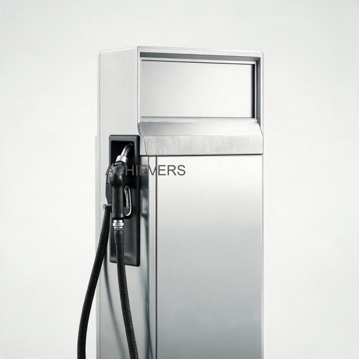
The internal architecture of modern Diesel Dispensers is a carefully engineered sequence of fluid conditioning and measurement stages. Unlike simple transfer pumps, a commercial-grade dispenser must condition the fluid to ensure the meter only measures pure liquid, free of vapor or air, which would otherwise cause over-registration.
The hydraulic circuit typically follows this path:
Suction Line → Pumping Unit → Bypass / Relief Valve → Air Eliminator → Flow Metering Unit → Delivery Hose → Automatic Shut-off Nozzle.
The Pumping Unit and Bypass Logic
Most industrial dispensers utilize a positive displacement rotary vane pump or a gear pump. These pumps generate consistent suction lift and handle the varying viscosities of diesel fuel across broad temperature ranges. Critical to this circuit is the internal bypass valve. When an operator releases the trigger on the dispensing nozzle, fluid flow abruptly stops. To prevent hydraulic shock (water hammer) and protect the internal seals, the bypass valve immediately opens, circulating the fuel internally within the pump housing at a governed pressure until the motor is deactivated.
Air Elimination Chamber
Before the fuel enters the metering unit, it must pass through an air eliminator. Diesel fuel drawn from a tank often contains entrained air or vaporized fuel (especially under high vacuum). The air eliminator acts as a centrifugal or gravity-based separation chamber. A float valve at the top of the chamber vents accumulated air back to the storage tank or atmosphere. If this air were allowed to pass through the meter, the meter would measure the volume of the air as if it were liquid fuel, resulting in significant billing or inventory errors.
The Metering Physics
For the measurement stage, dispensers predominantly use Positive Displacement Flow Meters, typically oscillating piston or rotary vane designs. These meters divide the flowing stream into discrete, known volumetric segments.
The theoretical flow rate calculation governing this volumetric measurement is expressed simply as:
Flow Rate (Q) = Swept Volume per Revolution (V) x Rotational Speed (N) x Volumetric Efficiency (E)
Because the swept volume is a fixed mechanical dimension, the accuracy relies heavily on the volumetric efficiency (E)—the ability of the meter to minimize internal fluid slippage between the moving components and the meter body.
2. The Control Stack: Preset Logic and Electronic Integration
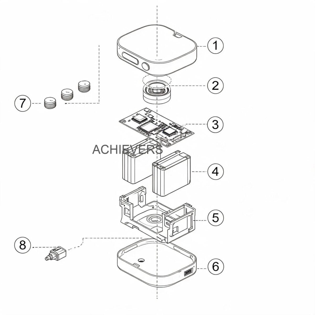
Once the mechanical meter measures the fluid volume, that physical rotation must be translated into actionable data. This is where the electronic control stack comes into play, elevating standard Diesel Dispensers into intelligent custody-transfer systems.
Pulse Generation (The Pulser)
Attached to the output shaft of the mechanical meter is a pulser (typically a magnetic or optical rotary encoder). As the shaft turns, the pulser generates a strict number of electrical pulses per unit of volume (e.g., 100 pulses per liter). High-end dispensers use dual-channel (quadrature) pulsers. By generating two signal waves offset by 90 degrees, the electronic calculator can determine both the volume of flow and the direction of rotation. This prevents fraudulent manipulation or vibration-induced pulse counting, as the system will ignore or subtract reverse flow.
Calculator Board and Preset Control
The pulses are fed into the electronic calculator board. This microprocessor handles real-time mathematical operations, multiplying the pulse count by the programmed calibration factor (K-factor) to display the dispensed volume and calculate totalizer values.
The preset controller allows operators to input a target volume. The controller communicates with a two-stage solenoid valve located downstream of the meter. When the dispensed volume approaches the preset limit (e.g., 0.5 liters before the target), the controller de-energizes the primary coil of the solenoid valve, reducing flow to a trickle. Once the exact volume is reached, the secondary coil closes, shutting off flow instantly without hydraulic shock.
Credential Authorization and System Integration
Advanced control boards allow dispensers to restrict fuel access. Using RFID, magnetic cards, or keypad credentials, the dispenser cross-references the user ID against a database. According to manufacturing designs like those seen in Achievers models, these dispensing cycles can be seamlessly networked to a central PC via RS485 or LAN interfaces, providing real-time inventory management, which is an absolute necessity for diesel dispensers for industrial fuel issue systems.
Technology Comparison: Positive Displacement vs. Turbine Meters in Fuel Dispensers
When engineering fuel systems, buyers often weigh PD meters against turbine options. Here is a comparative analysis for dispensing applications:
| Parameter | Positive Displacement (PD) Meter | Turbine Flow Meter |
| — | — | — |
| Measurement Principle | Volumetric (discrete fluid segments) | Velocity (rotor speed proportional to flow) |
| Accuracy at Low Flow | Excellent (maintains accuracy down to minimum flow) | Poor (rotor slip at low velocities) |
| Viscosity Sensitivity | Highly immune (accuracy often improves with higher viscosity) | Highly sensitive (calibration shifts with viscosity) |
| Flow Profile Requirements | None (can be installed immediately after elbows/valves) | Strict (requires 10D upstream / 5D downstream straight pipe) |
| Pressure Drop | Moderate to High (due to mechanical resistance) | Low (open flow path) |
| Typical Dispenser Use | Standard retail and industrial transfer dispensers | High-volume bulk transfer (e.g., aviation refueling) |
3. Complete Technical Specifications
For engineering teams drafting diesel dispensers specifications for industrial buyers, exact mechanical and electrical capabilities must be verified. Based on the robust architecture of the Lumen Instruments Achievers series (Models CE-101, CE-117, CE-202, CE-204), below are the baseline technical specifications reflecting global industrial standards.
| Parameter | Specification | Engineering Notes |
| — | — | — |
| Product Models | Achievers CE-101, CE-117, CE-202, CE-204 | Customized variations available per site requirement |
| Available Power Configurations | 12V DC, 24V DC, 220V AC | Allows for both stationary and mobile vehicle-mounted installations |
| Form Factor Options | Mobile, Hose Reel, Truck-mounted, Fixed Ground/Platform | Highly adaptable to diverse structural environments |
| Metering Technology | Positive Displacement (Mechanical or Electronic Output) | Ensures high accuracy independent of upstream piping constraints |
| Electromagnetic Compatibility | High EMC Rating | Prevents pulse miscounts caused by nearby heavy machinery VFDs |
| Access Control Integration | Credential-restricted electronic board | Prevents unauthorized fuel dispensing |
| Data Connectivity | PC-compatible network integration | Enables automated batch tracking and inventory reconciliation |
| Operating Temperature | -20 C to +60 C (standard global rating) | Ensure winterized diesel is used below cloud point to prevent waxing |
| Maximum Operating Pressure | Typically 3.5 Bar (50 PSI) | Limited by bypass valve spring tension to protect dynamic seals |
| Filtration Element | Integrated suction strainer | Crucial for protecting internal PD meter components from particulate damage |
4. Performance Characteristics and Error Sources
Even top-tier measurement equipment is subject to operational variables. Understanding metering error sources is critical for engineers implementing predictive maintenance.
1. Slippage and Viscosity Shift
In a PD meter, a microscopic clearance exists between the moving piston/rotor and the housing. A tiny amount of fluid "slips" through this gap unmeasured. If the diesel temperature rises significantly, its viscosity drops, making it thinner. Thinner fluid slips through the gaps more easily, causing the meter to under-register (delivering more fluid than displayed). Conversely, cold, thick diesel reduces slippage, causing slight over-registration.
2. Entrained Air and Vapor
If the suction line develops a tiny leak, or if the tank level drops too low, the pump will pull air. If the air eliminator is overwhelmed or malfunctions, this air passes through the meter. Because the meter measures pure volume, it will register the air as fuel, causing a massive financial discrepancy (the user pays for air).
3. Thermal Expansion
Diesel fuel has a coefficient of thermal expansion of approximately 0.083% per degree Celsius. If a dispenser is calibrated at 15 C but dispenses fuel at 35 C, the physical volume of the fuel has expanded by over 1.6%. While the meter accurately measures the expanded volume, the energy content or mass delivered is lower. Advanced electronic dispensers integrate RTD temperature probes to apply automatic API temperature volume compensation.
4. Mechanical Wear
Over millions of liters, abrasive particulates (if filtration fails) wear down the internal walls of the measuring chamber. This increases the mechanical clearances, drastically increasing slippage. Periodic calibration is required to adjust the electronic K-factor and compensate for this mechanical wear.
When to Use This Technology: Decision Matrix
| Application Scenario | Recommended Configuration | Justification |
| — | — | — |
| Remote Mining / Construction Sites | Mobile Diesel Dispensers (12V/24V DC) | Operates directly off service truck batteries; lightweight, highly portable. |
| Factory Central Fuel Depot | Fixed 220V AC Dispenser with PC Integration | High flow rates, continuous duty cycle, strict inventory tracking via network. |
| Marine / Offshore Loading | Hose Reel Dispenser with Mechanical Register | Long reach required; mechanical displays are preferred in highly corrosive or wash-down environments where electronics might fail if casing is compromised. |
5. Materials and Chemical Compatibility
The long-term reliability of a dispenser relies on matching the wetted materials to the chemical profile of the fluid. Diesel, while relatively stable, contains additives and varying sulfur contents depending on global market standards. Furthermore, the rise of Biodiesel (e.g., B20 to B100) requires specific elastomer selection, as standard Nitrile rubber degrades rapidly in the presence of bio-esters.
| Fluid / Chemical | Compatible? | Engineering Notes & Elastomer Selection |
| — | — | — |
| Standard Diesel (Ultra Low Sulfur) | Yes | Standard Cast Iron / Aluminum body with Nitrile (Buna-N) seals provides excellent life. |
| Biodiesel (B20 – B100) | Conditional | Requires Viton (FKM) or Teflon (PTFE) seals; Biodiesel aggressively degrades standard Buna-N. |
| Kerosene / Jet A1 | Yes | Lower lubricity than diesel; pump vanes may experience slightly accelerated wear over time. |
| Petrol / Gasoline | No (Standard setup) | Highly flammable; requires strict ATEX/Ex-proof electronics and different vapor recovery handling. |
| Hydraulic Oil | Yes | Higher viscosity may reduce maximum flow rate; increases suction vacuum required. |
| DEF / AdBlue | No | DEF is highly corrosive to cast iron and aluminum; requires Polypropylene or Stainless Steel wetted parts. |
| Water | No | Will cause rapid oxidation (rust) of cast iron internal metering components and pump rotors. |
| Ethanol | No | Attacks standard elastomers and aluminum components; requires specialized chemical handling setups. |
6. Calibration, Verification, and Certification
To maintain billing accuracy and internal inventory reconciliation, plant managers must establish a rigid calibration schedule. Working with a reputable diesel dispensers supplier for manufacturers ensures access to original calibration documentation and ongoing technical support.
Calibration ensures that the volume displayed on the electronic calculator perfectly matches the actual physical volume dispensed. International legal metrology standards (such as OIML R 117 for dynamic measuring systems for liquids other than water) dictate strict verification procedures.
Standard Field Calibration Procedure
For industrial instrumentation engineers, field verification is performed using a certified volumetric proving can (prover) designed with a narrow, graduated neck.
- Pre-wetting the Prover: Dispense a small amount of diesel into the proving can to wet the internal walls, then drain it completely according to the prover’s specified drain time (usually 30 seconds). This mimics the exact conditions of subsequent tests.
- Zero the Dispenser: Reset the totalizer/batch display on the dispenser to zero.
- High-Flow Dispense: Fully open the nozzle and dispense fuel at the maximum flow rate until the prover is filled to the nominal capacity mark (e.g., exactly 20.00 liters on the dispenser display).
- Settle and Read: Allow the fluid to settle to release any temporary foam. Read the physical volume on the graduated neck of the proving can.
- Temperature Measurement: Record the temperature of the diesel inside the prover. Apply correction factors using standard petroleum measurement tables to standardize the volume at 15 C.
- Adjust K-Factor: Calculate the percentage of error. If the physical volume in the prover is 19.80 liters but the display reads 20.00 liters, the meter is over-registering by 1%. Enter the calculator’s engineering mode and adjust the electronic calibration factor (pulse weight) accordingly to bring the error within the permissible +/- 0.5% tolerance.
Recalibration should ideally occur every 6 to 12 months, or immediately following any maintenance that involves opening the hydraulic circuit, replacing the strainer, or changing the pump vanes.

FAQ
Q: Why does the dispenser flow rate slow down drastically during operation?
A: A sudden drop in flow rate is almost always caused by a clogged internal suction strainer or a blocked external line filter. As the filter clogs, the pump experiences cavitation, pulling a high vacuum which can lead to vapor lock and accelerated mechanical wear.
Q: Can a standard diesel dispenser be used to pump petrol (gasoline)?
A: No. Petrol requires strictly certified ATEX/Ex-proof electrical enclosures due to its highly explosive vapor. Standard diesel dispensers, while having good EMC ratings, are not intrinsically safe for the volatile flashpoints of petrol.
Q: How often should the internal components be lubricated?
A: Diesel fuel inherently acts as a lubricant. The internal moving parts of the rotary pump and the volumetric flow meter are lubricated by the fluid itself. However, the external electric motor bearings may require scheduled greasing depending on the manufacturer's operational manual.
Q: What is the maximum distance a mobile dispenser can pump fuel?
A: The delivery distance depends entirely on the pump's discharge pressure curve and the hose diameter. A standard 3.5 Bar (50 PSI) pump pushing through a 1-inch hose can typically deliver up to 15-20 meters before friction losses severely diminish the flow rate.
Q: Why does my electronic totalizer show a few pulses of flow when the pump starts, even if the nozzle is closed?
A: This is usually due to hydraulic shock or line expansion. When the pump pressurizes the hose, the flexible rubber expands slightly, allowing a tiny volume of fluid to move through the meter. High-quality electronic dispensers often utilize software deadbands to ignore this micro-movement.
Q: Does upgrading to Biodiesel require modifying the dispenser?
A: Yes. Biodiesel blends above B20 act as powerful solvents that will degrade standard Nitrile (Buna-N) seals, leading to internal leaks and pressure loss. Ensure your supplier outfits the pump, meter, and nozzle with FKM (Viton) or PTFE seals if handling high-percentage biofuels.
Q: How does PC integration work for remote inventory management?
A: The electronic control board utilizes a digital output (often RS485 or LAN). Every time a transaction finishes, the board pushes a data packet containing the user ID, timestamp, and precise dispensed volume to a central software dashboard, eliminating manual logbooks.
For specialized fluid handling applications, precise engineering is non-negotiable. Whether you require standard standalone units or highly customized credential-based systems, our team is ready to analyze your site's specific duty cycles, temperature profiles, and data integration needs. Contact Lumen Instruments today with your required flow rates, fluid characteristics, and operational environment to receive a meticulously engineered Diesel Dispensers solution tailored to your plant's demands.