
Selecting the correct fluid handling equipment for industrial operations requires more than just matching a flow rate to a pipe size. For plant managers and instrumentation engineers, understanding the internal hydraulics and mechanical tradeoffs of Fuel Transfer Pumps is the difference between a system that lasts for years and one that fails prematurely due to cavitation, motor burnout, or seal failure. Industrial diesel transfer applications—especially in the demanding conditions of the Indian subcontinent—face unique challenges including long suction lifts, extreme ambient temperatures, high particulate contamination, and severe voltage fluctuations.
In this technical deep dive, we will explore the internal engineering that dictates pump performance. When analyzing how fuel transfer pumps work self priming bypass valve NPSH characteristics are the core elements that define reliable fluid handling. By examining the precise mechanics of positive displacement vane and gear designs, this guide provides the necessary Fuel Transfer Pumps specifications for manufacturers and industrial buyers to make informed, engineering-backed procurement decisions for construction yards, fleet fueling stations, and critical power generation infrastructure.
1. Working Principle: How Fuel Transfer Pumps Operate
The industrial diesel fuel transfer pump working principle relies primarily on positive displacement (PD) technology, specifically rotary vane and gear mechanisms. Unlike centrifugal pumps which rely on kinetic energy and velocity to move fluids, PD pumps trap a fixed volume of fluid and force it from the inlet to the outlet. This characteristic provides stable flow rates regardless of downstream pressure changes, making them ideal for dispensing applications.
The Rotary Vane Mechanism
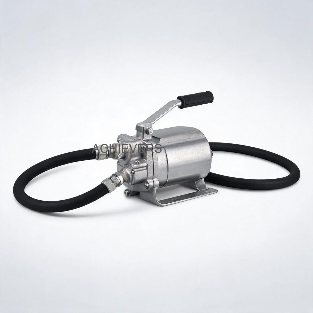
In our DC-powered transfer units, a sintered steel rotor is positioned eccentrically (off-center) within a precisely machined cast iron or die-cast aluminum pump cavity. Slotted into this rotor are sliding vanes made of durable acetal resin. As the direct current (DC) brush motor spins the rotor—typically at speeds around 2800 RPM for 40 L/min models—centrifugal force pushes the acetal resin vanes outward against the inner wall of the pump housing.
Because the rotor is eccentric, the volume between the vanes expands on the suction side and collapses on the discharge side.
Self-Priming Physics
This expanding volume on the inlet side creates a localized pressure drop (vacuum). Atmospheric pressure pressing down on the diesel fuel in the storage tank forces the liquid up the suction line to fill this vacuum. This is the essence of self-priming. A standard unit can achieve a dry suction lift of 2 to 4 meters, completely eliminating the need for foot valves or manual priming procedures which are highly impractical in mobile fuel dispensing or earth-moving machinery setups.
The Critical Role of the Bypass Valve
In industrial dispensing, flow is often abruptly stopped when a manual or automatic nozzle closes. Because a positive displacement pump displaces a fixed volume of fluid per revolution, closing the outlet valve while the motor is running (dead-heading) would cause an instantaneous, catastrophic pressure spike. To prevent ruptured hoses or motor stall, these pumps feature an incorporated internal bypass (relief) valve.
When discharge pressure exceeds the spring tension of the bypass valve, the valve opens, creating a short-circuit loop within the pump body. The diesel continuously circulates from the high-pressure discharge zone back to the low-pressure suction zone. However, running a pump in bypass mode generates rapid friction and heat, which is why these motors are strictly rated for a 30-minute intermittent duty cycle.
2. Complete Technical Specifications
To ensure optimal integration into your fluid handling system, all parameters must be carefully matched to site conditions. Below are the definitive technical specifications for the standard range of Fuel Transfer Pumps utilizing DC permanent magnet stators.
| Parameter | Specification | Engineering Notes |
| :— | :— | :— |
| Pumping Technology | Positive Displacement (Rotary Vane / Gear) | Ensures stable flow rate independent of discharge pressure variations. |
| Max Flow Rate Options | 40 L/min, 70 L/min, 80 L/min, up to 120 L/min | Achieved under free discharge conditions. Backpressure will marginally affect volumetric efficiency. |
| Motor Type | DC Brush Motor with Permanent Magnet Stator | Available in 12V DC and 24V DC. Provides high starting torque. |
| Duty Cycle | 30-Minute Intermittent Service | Critical parameter: Motor must cool down after 30 minutes to prevent thermal breakdown of stator insulation. |
| Pump Body Material | Cast Iron with Anti-Corrosion Paint / Die-Cast Aluminum | Lightweight yet sturdy construction; aluminum provides excellent atmospheric corrosion resistance. |
| Internal Wetted Parts | Sintered Steel Rotor, Acetal Resin Vanes | Sintered steel offers high wear resistance; acetal resin provides low friction and self-lubrication in diesel. |
| Protection Grade | IP55 | Dust protected and protected against low-pressure water jets; suitable for outdoor Indian site conditions. |
| Max Suction Lift | 2 to 4 meters | Depends on fluid viscosity and atmospheric pressure at site altitude. |
| Max Discharge Head | 10 meters (for 70 L/min model) | Represents the maximum vertical column of fluid the pump can support. |
| Port Connections | 3/4 inch and 1 inch BSP/NPT | Threaded connections for easy installation on L-shaped tanks or mobile skids. |
| Power Consumption | 4A (70L/min) to 44A (80L/min at 12V) | High current draw requires properly sized electrical cables to prevent voltage drop and motor stall. |
| Safety Features | Built-in Bypass Valve and Strainer | Strainer protects vanes from abrasive particulate; bypass protects against overpressure. |
Technology Comparison: Transfer Pump Mechanisms
To assist procurement heads in understanding why rotary vane is the preferred choice for diesel dispensing over other technologies, review this comparative analysis.
| Evaluation Parameter | Rotary Vane (Our Tech) | External Gear Pump | Centrifugal Pump |
| :— | :— | :— | :— |
| Self-Priming Capability | Excellent (High vacuum generation) | Good | Poor (Requires flooded suction) |
| Flow Stability Under Load | High (Consistent displacement) | High | Low (Flow drops as head pressure increases) |
| Handling of Thin Fluids (Diesel/Kerosene) | Excellent (Acetal vanes compensate for wear) | Moderate (Slip increases with thin fluids) | Excellent |
| Dry Run Tolerance | Low (Vanes require fluid lubrication) | Low | Moderate (Seal damage risk) |
| Cost to Performance Ratio for Dispensing | Optimal | High | Low (Not suitable for intermittent dispensing) |
3. Performance Characteristics and Error Sources
Deploying fuel transfer pumps in India for industrial diesel transfer requires a deep understanding of fluid dynamics and localized environmental challenges. A pump that performs perfectly in a climate-controlled test lab may struggle at a dusty construction site in Rajasthan operating at 45°C.
Net Positive Suction Head (NPSH) and Cavitation
A critical engineering concept in pump performance is NPSH. For any pump to operate without cavitating, the Net Positive Suction Head Available (NPSHa) must be strictly greater than the Net Positive Suction Head Required (NPSHr) by the pump.
The formula for calculating NPSHa at the pump inlet is:
NPSHa = P_atm + P_stat – P_friction – P_vapor
Where:
- P_atm = Atmospheric pressure at the installation site.
- P_stat = Static head (positive if tank is above pump, negative if drawing from underground).
- P_friction = Friction losses in the suction piping, strainer, and fittings.
- P_vapor = Vapor pressure of the diesel at the operating temperature.
The Thermal Effect on NPSH: In peak Indian summers, diesel temperatures residing in black, above-ground steel tanks can exceed 45°C. As temperature rises, the vapor pressure (P_vapor) of the fuel increases. Concurrently, high temperatures lower the viscosity of diesel. If NPSHa drops below NPSHr, localized boiling occurs inside the pump cavity. These vapor bubbles collapse violently against the sintered steel rotor when exposed to high discharge pressure, causing micro-pitting (cavitation), loud mechanical noise, and a massive drop in flow rate.
Engineering Mitigation: To maximize NPSHa, always install the pump as close to the tank as possible, minimize the length of the suction line, increase the suction pipe diameter to reduce P_friction, and ensure the built-in strainer is regularly cleaned.
Flow Stability Under Load and Volumetric Efficiency
For positive displacement pumps, theoretical flow is calculated as:
Theoretical Flow (Q) = Displacement Volume per Revolution x RPM
However, actual flow is always slightly less due to internal "slip"—the leakage of fluid from the high-pressure discharge side back to the low-pressure suction side through the microscopic clearances between the rotor, vanes, and housing. Volumetric efficiency dictates the actual output. When handling lower viscosity fuels like Kerosene, slip increases, slightly reducing the effective flow rate compared to standard High-Speed Diesel (HSD).
'When to Use This Technology' Decision Matrix
Use the following matrix to determine if a DC rotary vane fuel transfer pump is the correct solution for your specific site requirements:
| Application / Site Condition | Is Rotary Vane DC Pump Recommended? | Engineering Rationale |
| :— | :— | :— |
| Mobile Earth Moving Machinery Fueling | YES | 12V/24V DC power is natively available from vehicle batteries; compact size fits on skids. |
| High Volume Continuous Pipeline Transfer | NO | 30-minute duty cycle limit makes it unsuitable for 24/7 continuous operation. Centrifugal is better. |
| Underground Tank Suction (Max 3m depth) | YES | Strong self-priming capability (2-4m) pulls fuel efficiently without foot valves. |
| Viscous Lube Oil Transfer | NO | High viscosity creates excessive shear resistance, drawing high amps and stalling the DC motor. Use heavy-duty gear pumps. |
| Agricultural Tractor Refueling (Intermittent) | YES | Built-in bypass valve allows for safe start/stop dispensing at the nozzle. |
4. Materials and Chemical Compatibility
The longevity of any fluid handling system is strictly bound by the chemical compatibility between the pumped media and the internal wetted parts. The transfer pumps supplied for these applications utilize a rugged architecture: cast iron or die-cast aluminum bodies, sintered steel rotors, and acetal resin (Polyoxymethylene/POM) vanes.
Acetal resin is chosen specifically for its exceptional dimensional stability, high fatigue endurance, and resistance to petroleum-based solvents. Furthermore, the factory-lubricated bearings ensure a long operational life even under harsh environmental dust loading.
Chemical Compatibility Table for Standard Vane Transfer Pumps
| Fluid Type | Compatible? | Engineering Notes & Risks |
| :— | :— | :— |
| High-Speed Diesel (HSD) | YES | Ideal viscosity; provides natural lubrication to acetal resin vanes and rotor. |
| Kerosene / Lamp Oil | YES | Lower viscosity increases internal slip marginally but is fully chemically compatible. |
| Petrol / Gasoline | NO | Severe Safety Hazard. Standard DC brush motors are non-flameproof. Sparks can ignite petrol vapor. Requires PESO/ATEX certified explosion-proof motors. |
| Water / Aqueous Solutions | NO | Will cause rapid oxidation/rusting of the cast iron body and sintered steel rotor. Lacks lubricity, destroying vanes. |
| Heavy Fuel Oil (HFO) | NO | High viscosity exceeds the torque capacity of the permanent magnet DC motor, leading to massive amp draw and thermal overload. |
| Light Machine Oil | YES | Acceptable for old engine oil extraction or fresh oil replacement provided viscosity remains low. |
| Biodiesel (B100) | CONDITIONAL | Acetal resin handles biodiesel well, but internal elastomeric O-rings must be verified for Viton/FKM material to prevent swelling. |
| Chemical Solvents | NO | May chemically attack the anti-corrosion paint and internal seals. |
For applications requiring the exact measurement of dispensed fluids, these pumps must be paired with precision flow meters. We recommend integrating a Positive Displacement Flow Meter on the discharge side for highest accuracy custody transfer, or a standard Diesel Flow Meter for internal batch tracking.
5. Installation, Verification, and Maintenance Practices
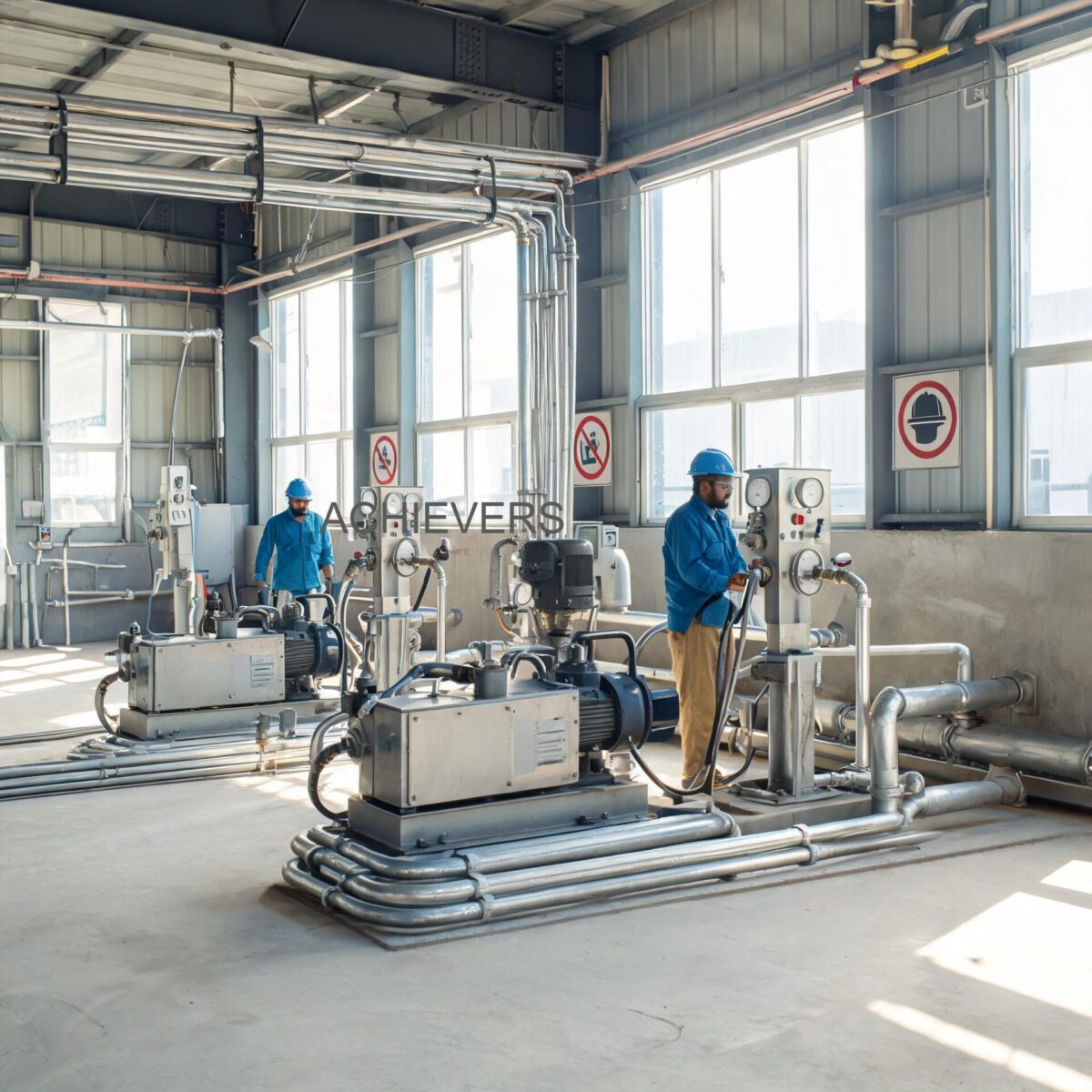
In the Indian industrial context—whether in mining setups in Odisha or construction sites in Maharashtra—improper installation is the leading cause of pump failure. Power quality (voltage drops over long cables) and severe dust contamination require strict adherence to commissioning protocols.
6-Step Standard Operating Procedure for Installation and Commissioning
- Mechanical Mounting: Secure the pump base to a rigid, vibration-free platform (such as an L-shaped tank mount). Because these are positive displacement pumps, vibration can loosen pipe fittings over time.
- Suction Piping Setup: Install the 3/4" or 1" suction line. The line must be airtight. Use thread sealant (PTFE tape or liquid thread locker compatible with diesel). A tiny air leak on the suction side will severely degrade the vacuum, preventing self-priming and causing erratic flow.
- Electrical Integration: Connect the motor to the 12V or 24V DC source. Crucial Engineering Note: For an 80 L/min pump drawing up to 44 Amps, use heavily gauged copper wire (minimum 6 sq.mm to 10 sq.mm depending on length) to prevent voltage drop. Low voltage at the motor terminals increases current draw and rapidly overheats the stator.
- Strainer Verification: Ensure the built-in strainer (or an external pre-filter of roughly 100 microns) is installed on the suction side. Contaminated diesel is a reality in India; hard particulate will shatter acetal resin vanes.
- Initial Priming and Venting: Although self-priming, initially filling the pump cavity with a small amount of diesel will wet the internal seals, creating a tighter hydraulic seal and significantly accelerating the initial prime while reducing dry-friction wear.
- Bypass Testing: Once flowing, briefly close the discharge nozzle while monitoring the motor sound. You should hear the bypass valve engage (a change in hydraulic pitch). Do not run in this dead-head state for more than 2-3 minutes.
Maintenance and Legal Metrology Notes
It is vital to distinguish between a transfer pump and a metering system. A transfer pump's sole job is to move fluid at a stable rate (e.g., 40, 70, or 80 L/min). It does not measure volume. If your application involves billing contractors or custody transfer, Indian Legal Metrology laws require the integration of a verified flow meter.
The pump requires minimal maintenance due to factory-lubricated bearings. However, the internal strainer must be cleaned every 100 hours of operation, and the acetal vanes should be inspected for wear every 1,500 hours of cumulative run time. If flow rate drops inexplicably despite a clean strainer and healthy voltage, vane wear is the most likely culprit.
FAQ
Q: Why is there a strict 30-minute duty cycle on these pumps?
A: These pumps utilize DC brush motors with permanent magnet stators. Due to their compact size and IP55 closed construction, they lack massive external cooling fans. Running beyond 30 minutes in high ambient temperatures prevents adequate heat dissipation, which can melt the copper winding insulation and cause a short circuit.
Q: Can I use this pump to transfer petrol or aviation fuel?
A: Absolutely not. Standard DC transfer pumps are not explosion-proof (non-flameproof). The internal brushes of a DC motor create micro-sparks during operation. Pumping highly volatile fluids like petrol poses an immediate risk of explosion. You must use PESO-certified explosion-proof equipment for volatile fluids.
Q: My pump is running, but it is not self-priming. What is the issue?
A: The most common cause is an air leak in the suction line. Because air is compressible, the pump will simply expand and compress the leaked air rather than building enough vacuum to lift the heavier diesel. Check all suction side threaded connections and ensure the suction lift does not exceed 4 meters.
Q: What happens if the dispensing nozzle is shut off but the pump is left running?
A: The built-in internal bypass valve will automatically open, recirculating the diesel within the pump body to prevent pressure buildup. However, this creates localized heat. The pump should not be left in bypass mode for more than 2 to 3 minutes.
Q: Will voltage fluctuations from my vehicle's battery damage the pump?
A: Severe voltage drops are dangerous. If a 12V system drops to 9V due to thin cabling or a dying battery, the motor loses torque, slows down, and draws significantly more amperage to try and move the fluid, which can burn out the thermal overload protector or the motor windings.
Q: Does this pump measure the amount of fuel transferred?
A: No, this is purely a transfer pump designed to move volume. To measure flow for inventory tracking or billing, it must be paired with an accurate mechanical or digital flow meter installed on the discharge line.
Q: How do I handle highly viscous old engine oil with this pump?
A: While broadly used for cleaning and replacing old motor oil, ensure the oil is relatively warm (which lowers viscosity). If the oil is cold and thick, it acts like molasses, drastically increasing the internal mechanical load and potentially causing the DC motor to stall.
As an established Fuel Transfer Pumps supplier in India, Lumen Instruments (under the "Achivers" brand) provides heavy-duty fluid handling solutions engineered for real-world site conditions. If you are designing a mobile refueling skid, upgrading your plant's backup generator fuel systems, or require reliable transfer equipment, contact our engineering team today with your required flow rate, fluid type, and power availability for a precise technical recommendation.