
In process-critical operations like petrochemical plants, pharmaceutical manufacturing, and heavy engineering, the unseen cost of flow measurement inaccuracy is staggering. A positive displacement meter recording a mere 1% under-registration on a 500 kVA diesel generator or an industrial boiler can translate to lakhs of rupees in unaccounted fuel costs annually. Unplanned downtime due to seized rotors or clogged strainers further halts production, elevating operational costs.
Implementing a methodical, engineering-grade preventive maintenance schedule is not optional; it is a financial necessity. This guide provides a comprehensive maintenance framework for Oil Flow Meters operating in challenging Indian industrial environments, focusing on controlling mechanical slip, preserving magnetic seal integrity, and maintaining totalizer accuracy.
1. Product Overview and Critical Wear Components
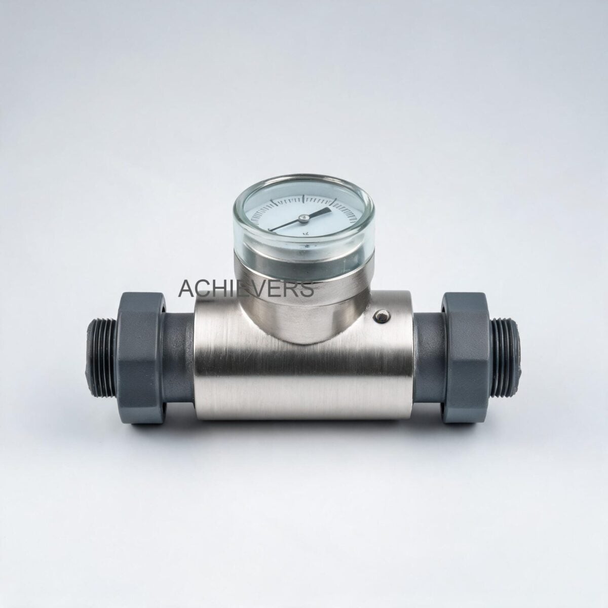
Lumen Oil Flow Meters operate on the positive displacement (PD) principle, utilizing a volumetric rotary piston or oval gear design. This mechanism ensures that a fixed volume of fluid is mechanically isolated and transferred with each rotation. Because the measurement relies on tight mechanical clearances rather than flow velocity, the accuracy is inherently immune to flow profile disturbances, making straight-run upstream piping unnecessary.
A critical engineering feature of these Oil Flow Meters is the magnetic coupling. By utilizing an effective magnetic coupling between the fluid-filled measuring chamber and the dry electronic/mechanical register, only the rotary mechanism is exposed to the metered fluid. This eliminates dynamic shaft seals (which are prone to leakage and wear), substantially extending service life.
Core Specifications
- Accuracy: Superior to +/- 0.5% of reading (customizable to +/- 0.2% upon request).
- Repeatability: Better than 0.02%.
- Line Sizes: 6mm to 150mm (1/4" to 6").
- Pressure Drop: Exceptionally low; can operate under a 1-inch gravity head of oil.
- Flange Standard: DIN ND10 specifications.
- Electronics: Optional Pulse Generator (PG 1) requiring 12-24V DC, Remote Totalizer (TF 200), and 4-20 mA FI converters for PLC/SCADA integration.
- Price Range: ₹9,999.00 – ₹62,499.00 (depending on line size, electronics, and construction).
Technology Comparison Table
To understand why PD meters dominate oil consumption monitoring compared to other technologies, consider the following engineering parameters:
| Parameter | Positive Displacement (Oval Gear/Rotary) | Turbine Flow Meter | Electromagnetic Flow Meter |
| — | — | — | — |
| Best Application | High viscosity fuels (Diesel, Furnace Oil, LDO) | Low viscosity, clean, high-velocity liquids | Water, conductive wastewater, slurries |
| Viscosity Dependency | Accuracy improves with higher viscosity (less slip) | Accuracy degrades with high viscosity | Independent of viscosity |
| Upstream Straight Run | Zero pipe diameters (0D) required | Minimum 10D upstream, 5D downstream | Minimum 5D upstream, 3D downstream |
| Pressure Drop | Low (Suitable for gravity drop / 1" head) | Moderate to High | Practically Zero |
| Conductivity Requirement | Non-conductive liquids (Oils) perfectly fine | Non-conductive liquids perfectly fine | Liquid MUST be conductive (>5 µS/cm) |
| Moving Parts | Yes (Rotors/Pistons) | Yes (Turbine blades/bearings) | No moving parts |
'When to Use This Technology' Decision Matrix
- Choose Positive Displacement Oil Meters when: Measuring high-value, viscous fluids (HSD, LDO, Furnace Oil) for boiler consumption, generator monitoring, or tank draw-offs where maximum volumetric accuracy (+/- 0.5%) is required, and gravity-fed piping eliminates high-pressure pumping.
- Choose Turbine Meters when: Dispensing low-viscosity fuels at very high flow rates where a slight drop in low-end accuracy is acceptable, and long straight pipe runs are available.
- Choose Electromagnetic Meters when: Measuring conductive liquids like hard bore-well water, effluent, or slurry where pressure drop must be zero. (Note: Mag meters cannot measure hydrocarbons).
2. Preventive Maintenance Schedule
For industrial maintenance teams adhering to ISO 9001 or Indian Legal Metrology standards, scheduled interventions prevent the degradation of mechanical clearances (which causes slip) and electronic drift.
| Task | Frequency | Responsible | Est. Time | Notes |
| — | — | — | — | — |
| Visual Leak Inspection | Daily | Plant Operator | 5 mins | Check DIN ND10 flange joints and register base for weeping. |
| Differential Pressure Check | Weekly | Maintenance Tech | 10 mins | High DP indicates clogged strainer; check gauges across bypass loop. |
| 100-Mesh Strainer Cleaning | Monthly | Fitter / Tech | 30 mins | Crucial for preventing particulate damage to rotors. |
| Totalizer Orientation Check | Quarterly | Instrument Tech | 15 mins | Ensure mechanical register rotation is smooth in all 4 cardinal positions. |
| PG 1 Pulse Generator Voltage Test | Quarterly | Electrical Tech | 20 mins | Verify 12-24V DC supply from remote totalizer; inspect 3-core cable. |
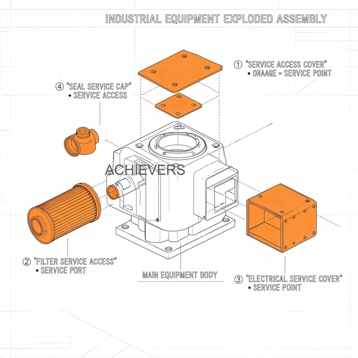
| Magnetic Coupling Inspection | Bi-Annually | Instrument Eng. | 45 mins | Remove register top; check magnetic drive strength and alignment. |
| Rotary Piston/Gear Clearance Check | Annually | Specialist | 2 hours | Inspect for scoring/wear from contaminated oil; verify slip tolerances. |
| Seal & O-Ring Replacement | Annually | Fitter | 1 hour | Replace measuring chamber O-rings as preventive measure. |
| Calibration Verification (Proving) | Annually | Metrology Auditor | 2-3 hours | Perform gravimetric or master-meter proving to certify +/- 0.5% accuracy. |
| Electronics Desiccant Replacement | Post-Monsoon | Instrument Tech | 15 mins | Replace silica gel in TF 200/BTF 200 enclosures to prevent PCB corrosion. |
3. Step-by-Step Procedures for Key Tasks
Maintaining Positive Displacement Flow Meters requires methodical execution. Below are the standard operating procedures for the two most critical maintenance tasks.
Procedure 1: 100-Mesh Strainer Isolation and Cleaning
Particulate contamination (rust, silica, sludge) in Indian fuel supply chains is a primary cause of rotor seizure. A strainer of at least 100 mesh must be fitted upstream.
- Notify Operations: Inform the control room that the boiler or DG set fuel line will be switched to the bypass loop.
- Engage Bypass: Slowly open the bypass valve to route fuel around the flow meter and strainer assembly.
- Isolate Meter: Close the upstream, then the downstream isolation valves flanking the flow meter and strainer.
- Depressurize: Open the bleed valve on the strainer body to safely relieve trapped line pressure into a containment vessel.
- Extract Mesh Basket: Unbolt the strainer cap and carefully pull out the 100-mesh cylindrical screen.
- Clean the Mesh: Submerge the screen in a clean solvent (like kerosene or diesel). Use a soft bristle brush (never wire) to remove embedded particulates. Blow out with low-pressure compressed air from the outside in.
- Inspect for Damage: Hold the mesh up to a light source. If any tears or stretched weaves are visible, discard and replace the mesh basket immediately to protect the meter's rotors.
- Reassemble and Normalize: Install the cleaned mesh, replace the cap gasket if compressed, and bolt down. Slowly crack open the upstream isolation valve to purge air through the bleed valve. Once oil flows without bubbles, close the bleed, fully open isolation valves, and close the bypass.
Procedure 2: Field Calibration Verification and Slip Control
Over time, abrasive wear increases the clearance between the rotary piston and the measuring chamber. This allows fluid to bypass the rotors (known as "slip"), resulting in under-registration.
Engineering Calibration Note:
Slip is inversely proportional to viscosity and directly proportional to differential pressure.
Meter Factor (MF) = True Volume / Indicated Volume.
If the MF drifts above 1.005 (indicating more than 0.5% slip), mechanical calibration is required using the step-less alignment system.
- Prepare the Master Vessel: Procure a Legal Metrology certified standard proving measure (e.g., a 200-liter conical bottom tank with a sight glass).
- Establish Flow: Start the transfer pump and circulate oil through the system to stabilize temperature and viscosity.
- Purge Air: Ensure the upstream air release system is functioning. Trapped air meters as liquid and will severely skew calibration results.
- Zero the Totalizer: Reset the TF 200 Remote Totalizer or the mechanical register to zero.
- Conduct the Draw: Dispense oil at the normal operating flow rate (e.g., 80% of max capacity) directly into the proving measure until it reaches the nominal neck mark.
- Record Variables: Note the exact volume on the prover, the indicated volume on the flow meter, and the fluid temperature.
- Calculate Meter Factor: Divide the prover volume by the meter's indicated volume. Apply thermal expansion correction factors for the oil based on API tables if the temperature deviates from the baseline.
- Adjust the Calibration: If the error exceeds +/- 0.5%, access the step-less calibration mechanism on the register head. Turn the adjustment screw clockwise to increase indicated volume (reduce meter factor) or counter-clockwise to decrease, based on manufacturer increments. Repeat the draw to verify.
4. On-Site Spare Parts to Stock
Procurement teams must ensure that specific consumable parts are readily available. Waiting for parts during an emergency shutdown can cost thousands in lost production.
| Part Description | Component Type | Recommended Stock Qty | When to Replace |
| — | — | — | — |
| 100-Mesh Strainer Basket | Consumable | 2 per meter size | Every 6 months, or immediately if torn/deformed. |
| Measuring Chamber O-Rings | Elastomer Seal | 3 sets | Annually, or whenever the meter body is opened. |
| Magnetic Coupling Set | Drive Component | 1 set | If slippage occurs between rotor and register without fluid slip. |
| PG 1 Pulse Generator | Electronic | 1 unit | If 12-24V input is verified but no pulse output is detected on 3-core cable. |
| Flange Gaskets (DIN ND10) | Static Seal | 4 per meter | Upon any pipeline dismantling or leak detection. |
5. Diagnosing Maintenance-Related Failures
When operators report discrepancies in fuel consumption, rapid root-cause analysis is required.
| Failure Symptom | Missed Maintenance Task | Corrective Action |
| — | — | — |
| Meter Under-Registering (High Slip) | Annual clearance check / Strainer cleaning | Check for rotor wear from particulates. Recalibrate step-less alignment or replace measuring chamber. |
| Meter Over-Registering | Air release valve maintenance | Inspect and repair upstream air eliminator. The meter is counting air pockets as liquid. |
| Complete Mechanical Lockup | Monthly strainer cleaning | Isolate meter, open chamber, remove debris causing rotor seizure. Polish minor scoring. |
| Register Shows No Flow (Line Active) | Magnetic coupling inspection | Check if magnetic drive is decoupled or demagnetized. Replace coupling. |
| TF 200 Display Blank / Erratic | Electronics desiccant replacement | Check for moisture on PCBs or verify 12-24V DC power supply to the PG 1 unit. |
| High Pressure Drop Across Meter | Strainer cleaning / Filter check | Clean the 100-mesh strainer immediately. Check viscosity parameters (oil may be too cold). |
6. Extending Service Life in Indian Conditions
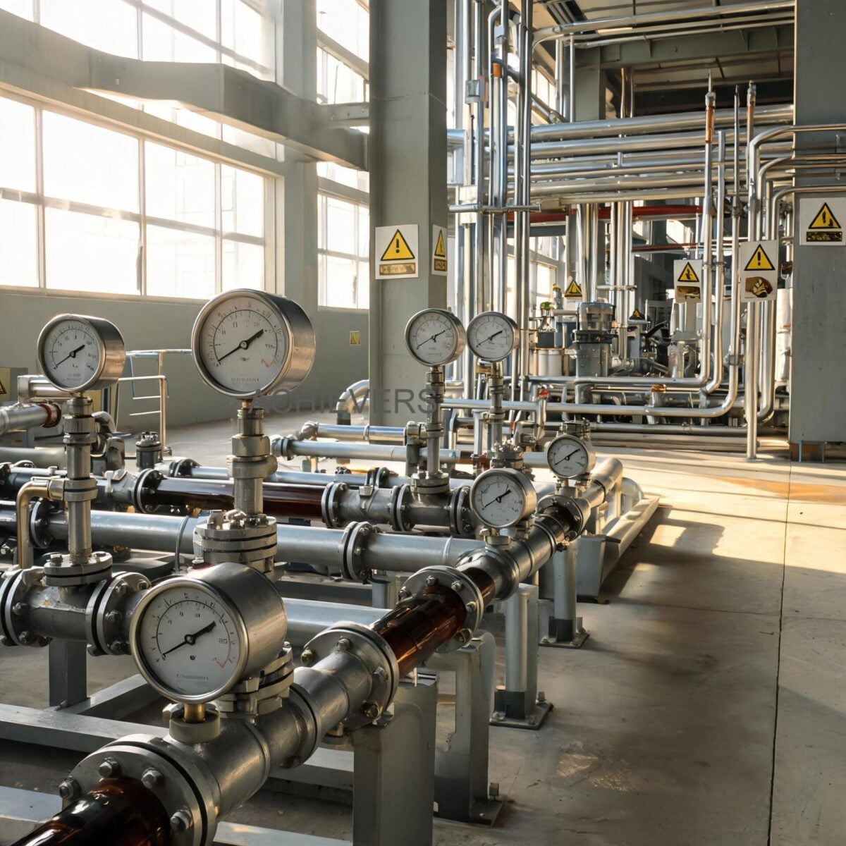
Indian industrial environments present unique challenges that will degrade metering systems if not proactively managed.
- Handling High Ambient Temperatures: In regions like Rajasthan or Gujarat, summer ambient temperatures in boiler houses can exceed 50°C. Ensure that Electronic Combined Batching Units (BTF 200) are housed in IP-rated enclosures with adequate thermal shading. High heat can accelerate the drying out of mechanical register lubricants.
- Monsoon Humidity and PCB Corrosion: The high humidity of the Indian monsoon causes condensation inside electrical enclosures. Ensure conformal coating is intact on all PG 1 and TF 200 circuit boards. Place industrial silica gel packets inside the terminal boxes and replace them every June and September.
- Voltage Fluctuations: Unstable power grids require robust electrical protection. The PG 1 pulse generator requires a clean 12 to 24-volt control supply. Always route this supply through a high-quality SMPS with surge protection to prevent pulse spikes from destroying the FI converter's 4-20 mA output generation.
- Fuel Contamination and Hard Water: Contaminated diesel (mixed with solvents or water) can alter the lubricating properties of the fluid, which the rotary piston relies upon. Furthermore, if water separates in the storage tank and passes through the meter, it can cause internal corrosion. Ensure primary storage tanks have proper water draw-off procedures implemented.
- Viscosity Shifts in Winter: In Northern India, Furnace Oil and LDO become highly viscous during winter nights. Ensure line tracing (heating) is functional before the flow meter to prevent the oil from solidifying and shearing the magnetic coupling upon pump startup.
FAQ
Q: Does the Legal Metrology Act in India require periodic calibration of oil flow meters?
A: Yes. If the flow meter is used for custody transfer, commercial billing, or receiving fuel from oil marketing companies, it must be verified and stamped by the Legal Metrology Department annually. Internal process meters for DG sets or boilers do not strictly require state stamping but should be calibrated annually for ISO compliance.
Q: Can I run the meter without the 100-mesh strainer to reduce pressure drop?
A: Absolutely not. Positive displacement meters have microscopic clearances between the rotor and the chamber. Without a strainer, weld slag, rust, or dirt will enter the chamber, causing catastrophic scoring, immediate loss of accuracy, and eventual mechanical seizure.
Q: What is the maximum pressure drop across this meter during gravity unloading?
A: The rotary piston design allows for an exceptionally low pressure drop. The meter can operate effectively under just a 1-inch gravity head of oil, making it ideal for unloading storage tanks without the need for auxiliary pumping systems. For gravity unloading, 80mm or 50mm line sizes are recommended.
Q: Why is my mechanical totalizer spinning, but my control room PLC is not receiving a flow rate?
A: This points to an electronic failure in the signal chain. First, verify that the PG 1 Pulse Generator is receiving its 12-24V DC power supply via the 3-core cable. If power is present, check the FI converter module that translates the raw pulse into the 4-20 mA signal for the PLC.
Q: Can these meters handle hot fluids like thermopack oil?
A: Yes, but temperature ratings must be strictly observed. Standard models handle standard fuel temperatures, but specialized high-temperature seals and clearances are required for thermal fluid applications to account for the thermal expansion of the internal rotors.
Q: How do I know if my flow meter is suffering from 'slip'?
A: Slip is indicated when the meter consistently under-registers compared to a known physical volume (like a calibrated tank dip). It is more pronounced with low-viscosity fluids at lower flow rates. If your meter factor during proving calculation shows a drift exceeding +0.5%, mechanical wear leading to slip is the likely culprit.
Q: Is straight piping required before and after the meter?
A: Unlike Turbine Flow Meters or electromagnetic meters that require fully developed flow profiles, positive displacement oil meters are completely unaffected by external piping elements. You can install valves or elbows directly adjacent to the meter flanges without impacting the +/- 0.5% accuracy.
Ready to optimize your fuel consumption monitoring and eliminate unaccounted oil losses? Contact our engineering team today with your specific application, line size (6mm to 150mm), flow rate requirements, and site conditions. We will help you select, specify, and price the ideal metering solution for your plant.