
In Indian industrial operations, high-speed diesel (HSD) is one of the highest operating expenses. Whether firing captive power plants, fueling heavy earth-moving machinery, or running large-scale kilns, inaccurate fuel measurement translates directly into millions of rupees in lost operational efficiency or pilferage. For plant managers and instrumentation engineers, the reliability of Diesel Flow Meters is not just a maintenance checkbox; it is a critical audit and cost-control mechanism. Unplanned failures or calibration drifts in these meters lead to catastrophic unaccounted losses, billing disputes, and production downtime.
Implementing a rigorous preventive maintenance (PM) schedule for your Diesel Flow Meters is the only way to ensure sustained accuracy, minimize slippage, and control the wear of internal seals and bearings. Given the unique challenges of the Indian industrial environment—ranging from heavily contaminated fuel and extreme ambient temperatures to fluctuating voltages and high monsoon humidity—a generic maintenance approach is insufficient. This guide provides a plant-ready, highly technical preventive maintenance framework designed specifically to maximize the operational lifespan and metrological accuracy of Diesel Flow Meters in harsh site conditions.
1. Product Overview and Critical Wear Components
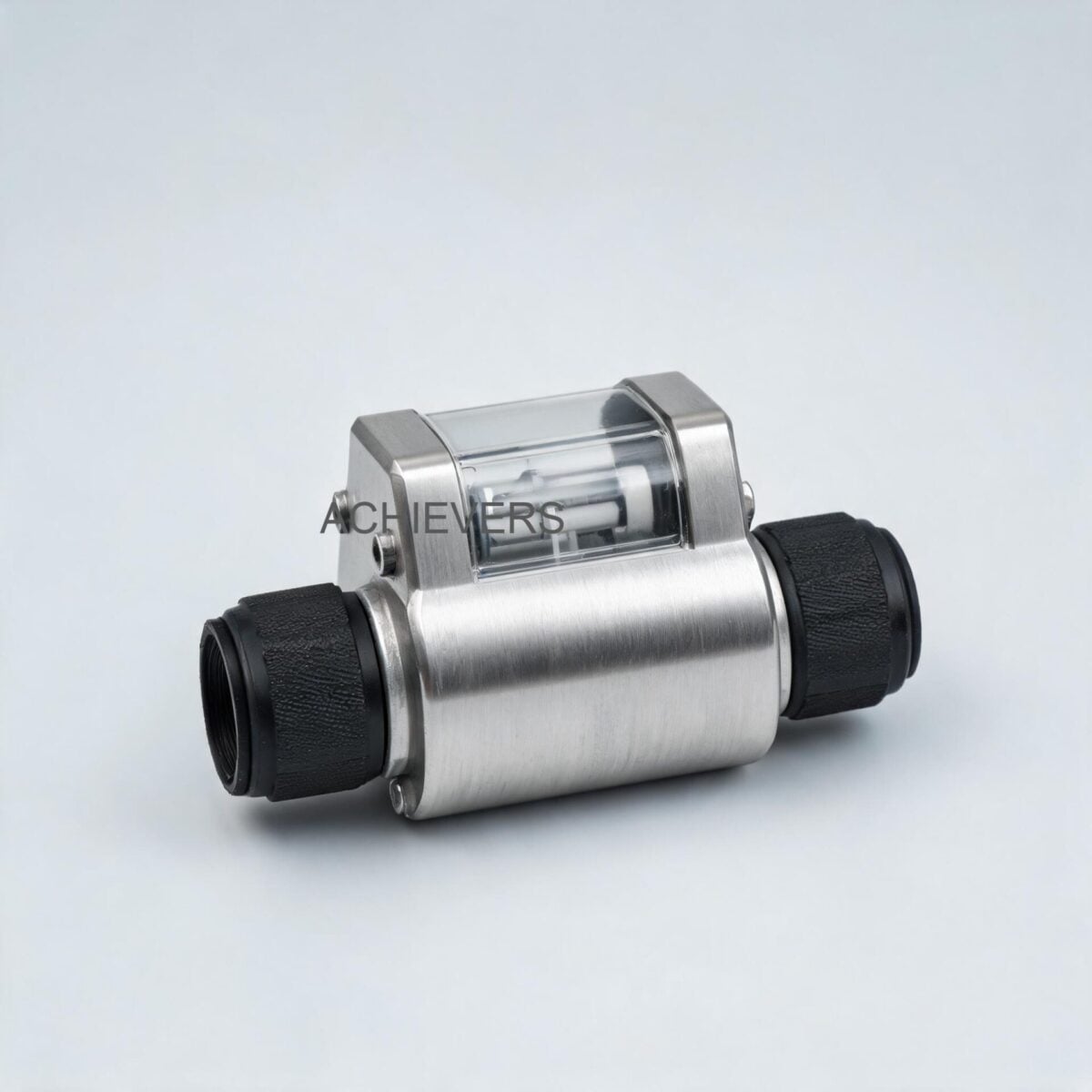
Positive Displacement (PD) technology remains the industry standard for diesel measurement because it directly measures the volume of the liquid passing through the meter. The mechanism repeatedly entraps fluid in measuring chambers—conceptually similar to filling a fixed-volume bucket and emptying it downstream. The number of volumetric entrapments dictates the total flow.
To maintain strict accuracy, these rotating parts operate with extremely tight machining tolerances. The fluid itself forms a capillary seal between the rotating elements (like oval gears, rotary vanes, or nutating discs) and the meter body. When these tolerances are compromised by abrasive wear, fluid bypasses the measuring chamber without being recorded. This phenomenon, known as slippage, is the primary cause of under-reading in aging meters.
Critical wear components include:
- Rotors/Vanes: Subject to abrasion from particulate matter in dirty fluids.
- Sealing Surfaces: Wear leads to increased clearances and higher slippage.
- Bearings: Bear the mechanical load of the rotating assembly. Large pressure drops across the meter will prematurely wear or catastrophically damage these bearings.
- Mechanical Registers/Digital Transmitters: Mechanical gears (as seen in models like the Achievers CE-113 or CE-110) can wear over time, while digital transmitters (like the CE-112 with 4-20 mA or RS-485 outputs) are susceptible to electrical transients.
- Air Eliminators: Mechanical floats and valves that expel entrapped air before it enters the measuring chamber.
Technology Comparison Table
No single flow technology fits every application. Below is a comparative analysis of Positive Displacement meters against other common measurement technologies to highlight why PD is preferred for diesel, yet requires specific maintenance.
| Parameter | Positive Displacement (Diesel Flow Meters) | Turbine Flow Meters | Electromagnetic Flow Meters |
| — | — | — | — |
| Measurement Principle | Direct Volumetric (Fluid entrapment) | Velocity (Rotor speed) | Faraday's Law (Conductivity) |
| Viscosity Handling | Excellent (Accuracy improves as viscosity increases) | Poor (High viscosity dampens rotor, shifting K-factor) | N/A (Requires conductive fluid, useless for diesel) |
| Slippage Susceptibility | Yes (Worn seals or low viscosity increases slippage) | No (But susceptible to bearing drag) | No |
| Pressure Drop | Moderate to High (Increases with viscosity) | Low | Zero (Full bore) |
| Particulate Sensitivity | Very High (Requires strict upstream filtration) | High (Blades can chip or jam) | Low |
| Accuracy Rating | Up to 0.1% to 0.5% (Custody Transfer grade) | 0.5% to 1.0% | 0.2% to 0.5% (For water/chemicals) |
| Typical Indian Price Range | ₹9,999 – ₹62,499 (e.g., Achievers CE series) | ₹15,000 – ₹85,000 | ₹25,000 – ₹1,50,000 |
When to Use This Technology: Decision Matrix
- Use Positive Displacement Meters When: You are measuring clean, non-conductive hydrocarbons (HSD, marine diesel, lubricating oils) with varying viscosities. You require high precision at low flow rates, and you have limited straight pipe runs available (PD meters do not require straight flow conditioning runs).
- Use Turbine Flow Meters When: You have clean, low-viscosity fluids at high, steady flow rates, and require a highly economical insertion or inline solution where a slightly lower accuracy is acceptable.
- Use Electromagnetic Meters When: You are measuring conductive liquids (water, wastewater, conductive chemicals, hard water). Never use for diesel or oil.
Engineering & Calibration Note: The Role of Viscosity and Slippage
In positive displacement fluid mechanics, kinematic viscosity plays a dominant role in meter accuracy. As fluid viscosity increases, slippage decreases, resulting in an increased pressure drop across the meter but surprisingly improving accuracy at low flow conditions. Conversely, if a meter is calibrated on a high-viscosity oil and then deployed for a lighter fluid like HSD, the varying amounts of slippage will cause a measurement error (under-reading). Always ensure the fluid used during volumetric proving closely matches the operating fluid's viscosity at site ambient temperatures.
2. Preventive Maintenance Schedule
To mitigate bearing wear, seal degradation, and slippage, implement this strict PM schedule. It is tailored for the typical 24/7 duty cycles of Indian petrochemical, construction, and power generation sectors.
| Task | Frequency | Responsible | Est. Time | Notes / Acceptance Limits |
| — | — | — | — | — |
| Visual & Leak Inspection | Daily | Plant Operator | 5 mins | Check for diesel weeping at flanges, O-rings, and mechanical register seals. Zero tolerance for leaks. |
| Differential Pressure (DP) Check | Daily | Field Engineer | 5 mins | Monitor DP across the upstream strainer. Clean if DP exceeds 0.5 bar to prevent rotor starvation. |
| Strainer/Filter Cleaning | Weekly | Maintenance Tech | 30 mins | Remove and clean the Y-strainer or basket filter element. Vital to prevent particulate ingress. |
| Air Eliminator Vent Check | Monthly | Maintenance Tech | 15 mins | Ensure the air eliminator float valve is free-moving and expelling air, not liquid fuel. |
| Bearing Noise / Vibration Analysis | Monthly | Reliability Eng. | 15 mins | Listen for grinding or uneven mechanical rotational noises indicating bearing wear or rotor dragging. |
| Display/Terminal Inspection | Quarterly | Instrument Tech | 20 mins | On digital units (CE-111, CE-112), inspect terminal blocks for corrosion due to monsoon humidity. |
| Volumetric Proving (Calibration) | Bi-Annually | Metrology Team | 2 hours | Prove against a Legal Metrology certified standard prover tank. Adjust mechanical/digital calibrator. |
| Seal & O-ring Replacement | Annually | Maintenance Tech | 1.5 hours | Replace body O-rings and register shaft seals to prevent environmental ingress and internal leaks. |
| Rotor Clearance Inspection | Annually | Maintenance Tech | 2 hours | Feeler gauge check of rotor-to-body clearances to assess abrasive wear and slippage potential. |
| Complete Overhaul & Recalibration | 2-3 Years | OEM / Supplier | 1-2 weeks | Complete bearing replacement, rotor re-machining (if applicable), and full Legal Metrology restamping. |
3. Step-by-Step Procedures for Key Tasks
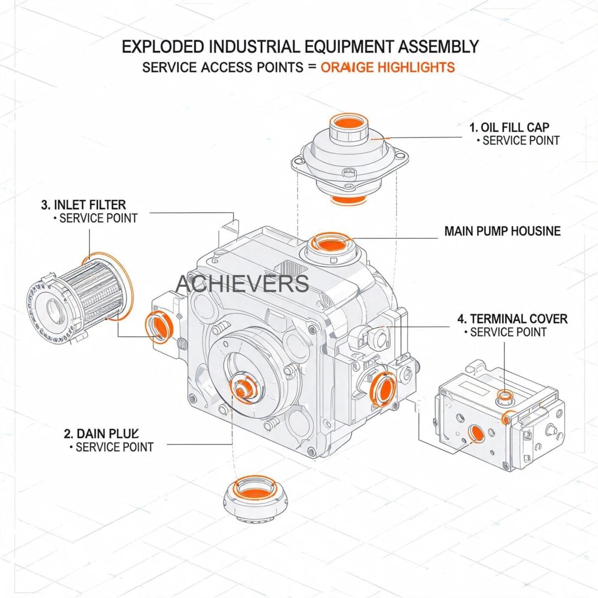
Standard operating procedures (SOPs) are critical to ensure maintenance does not inadvertently introduce contaminants or damage precision-machined internal parts.
Procedure 1: Upstream Strainer and Filter Cleaning
Operating Diesel Flow Meters in dirty liquids without effective upstream filtration will cause catastrophic bearing failure, rotor plugging, and severely degraded accuracy due to abrasive wear on the sealing surfaces.
- Isolate the Line: Close the upstream and downstream isolation valves to block flow to the meter assembly.
- De-pressurize and Drain: Safely vent the pressure using the strainer body vent valve. Drain the residual diesel into a safe, static-grounded containment vessel.
- Remove the Filter Housing: Unbolt the strainer cap carefully. Keep the O-ring or gasket aside for inspection.
- Extract the Mesh Basket: Pull the stainless steel filter element straight out. Inspect for tears, collapses, or stretching of the mesh. (Standard for diesel is typically a 40 to 80 mesh screen).
- Clean the Element: Wash the basket in a clean solvent bath (like kerosene or a specialized parts washer). Use compressed air (blowing from the outside in) to dislodge embedded particulates. Never use wire brushes which can distort the mesh spacing.
- Inspect the Housing: Wipe out the inside of the strainer housing. Check for heavy sludge buildup, rust, or sand, which could indicate severely contaminated fuel shipments.
- Replace O-Rings: Always fit a new, lightly lubricated Viton O-ring to the strainer cap to prevent air ingress (which causes meter over-reading).
- Reassemble and Prime: Bolt the cap back on evenly using a crisscross pattern. Slowly crack open the upstream valve to prime the housing, using the vent to bleed off trapped air before fully opening the valves.
Procedure 2: On-Site Calibration Verification and Slippage Check
Air bubbles and shifting gas pockets will cause over-reading (as air volume is measured as liquid volume), while worn seals cause under-reading (slippage). Regular proving quantifies these errors.
- Prepare the Standard: Ensure you have a PESO/Legal Metrology certified volumetric prover tank (e.g., 100 Liters or 500 Liters) placed on a leveled surface.
- Purge the System: Run fuel through the meter and bypass the prover to ensure all air is purged from the meter and air eliminator system.
- Zero the Meter: Reset the mechanical register (e.g., on an Achievers CE-113) or digital totalizer (e.g., on a CE-111) to absolute zero.
- Dispense the Batch: Open the flow to the prover tank at the normal operating flow rate. Shut off precisely when the meter reads the target test volume (e.g., exactly 100.0 Liters).
- Settle and Read: Allow the fluid in the prover tank to settle. Read the actual volume on the prover tank’s sight glass meniscus.
- Record Temperatures: Immediately record the temperature of the diesel inside the prover tank and at the meter. Apply API gravity/temperature correction factors if there is a significant delta (though usually negligible for fast, on-site ambient tests).
- Calculate the Error: Use the basic volumetric error formula:
- Adjust and Seal: If the error exceeds the acceptable tolerance (usually +/- 0.1% to 0.5% depending on custody transfer requirements), adjust the meter's mechanical calibration dial or the digital K-factor. Run a verification batch, then apply wire seals to prevent tampering.
Percentage Error = ((Meter Indicated Volume – Prover Actual Volume) / Prover Actual Volume) * 100
4. On-Site Spare Parts to Stock
Supply chain delays for precision instrumentation components can cripple plant operations. Relying entirely on breakdown maintenance is not an option. Keep the following spares localized in your plant’s instrumentation store, particularly if using mechanical (CE-110, CE-113) or digital (CE-111, CE-112) variations.
| Part Description | Component Type | Recommended Stock Qty | When to Replace |
| — | — | — | — |
| Strainer Mesh Baskets | Consumable | 2 per meter | If mesh is torn, crushed due to high DP, or heavily varnished. |
| Viton O-Ring / Gasket Kit | Consumable | 3 sets per meter | Annually during inspection, or immediately if leaks occur. |
| Air Eliminator Float/Valve | Wear Part | 1 per 3 meters | If the meter is violently over-reading due to air passing through. |
| Main Rotor Bearings | Fast Wear Part | 1 set per meter | Every 2-3 years, or immediately if excessive pressure drop/noise is noted. |
| Mechanical Register Head | Assembly (for CE-110/113) | 1 per site | If the display gears strip or totalizer fails to increment smoothly. |
| Pulse Transmitter PCB | Electronics (for CE-112) | 1 per site | If erratic pulses are sent to the PLC due to electrical surges. |
5. Diagnosing Maintenance-Related Failures
Even with a strong PM schedule, adverse conditions in diesel handling (like offloading from non-standardized tankers) can induce sudden faults. Instrumentation engineers must diagnose these rapidly.
| Failure Symptom | Most Likely Missed Maintenance Task | Corrective Engineering Action |
| — | — | — |
| Meter Over-Reading (Indicates more than actual) | Failure to inspect/clean the Air Eliminator. Air is being metered. | Clean or replace the air eliminator float valve. Ensure upstream piping isn't drawing in air through bad pump seals. |
| Meter Under-Reading (Slippage) | Failure to monitor particulate ingress, leading to worn rotors/sealing surfaces. | Perform rotor clearance checks. Re-calibrate if wear is minor; replace measuring chamber if wear is severe. |
| Sudden Complete Stoppage / No Flow | Skipped strainer cleaning; severe dirt plugging the rotor assembly. | Isolate, de-pressurize, and dismantle the measuring chamber. Clean rotors and check for bearing seizure. |
| Erratic or No Digital Output (on CE-111/112) | Failure to check terminal enclosure for moisture ingress. | Inspect terminal block. Replace pulse transmitter PCB if shorted. Ensure proper cable gland sealing. |
| Abnormally High Pressure Drop | Ignored daily DP checks across the strainer/filter. | Immediately clean the strainer. Check max pressure drop spec to ensure bearings are not already damaged. |
| Diesel Leaking from Register Shaft | Failure to perform annual dynamic seal replacement. | Isolate meter and replace the mechanical packing or shaft lip seal isolating the wet side from the register. |
6. Extending Service Life in Indian Conditions
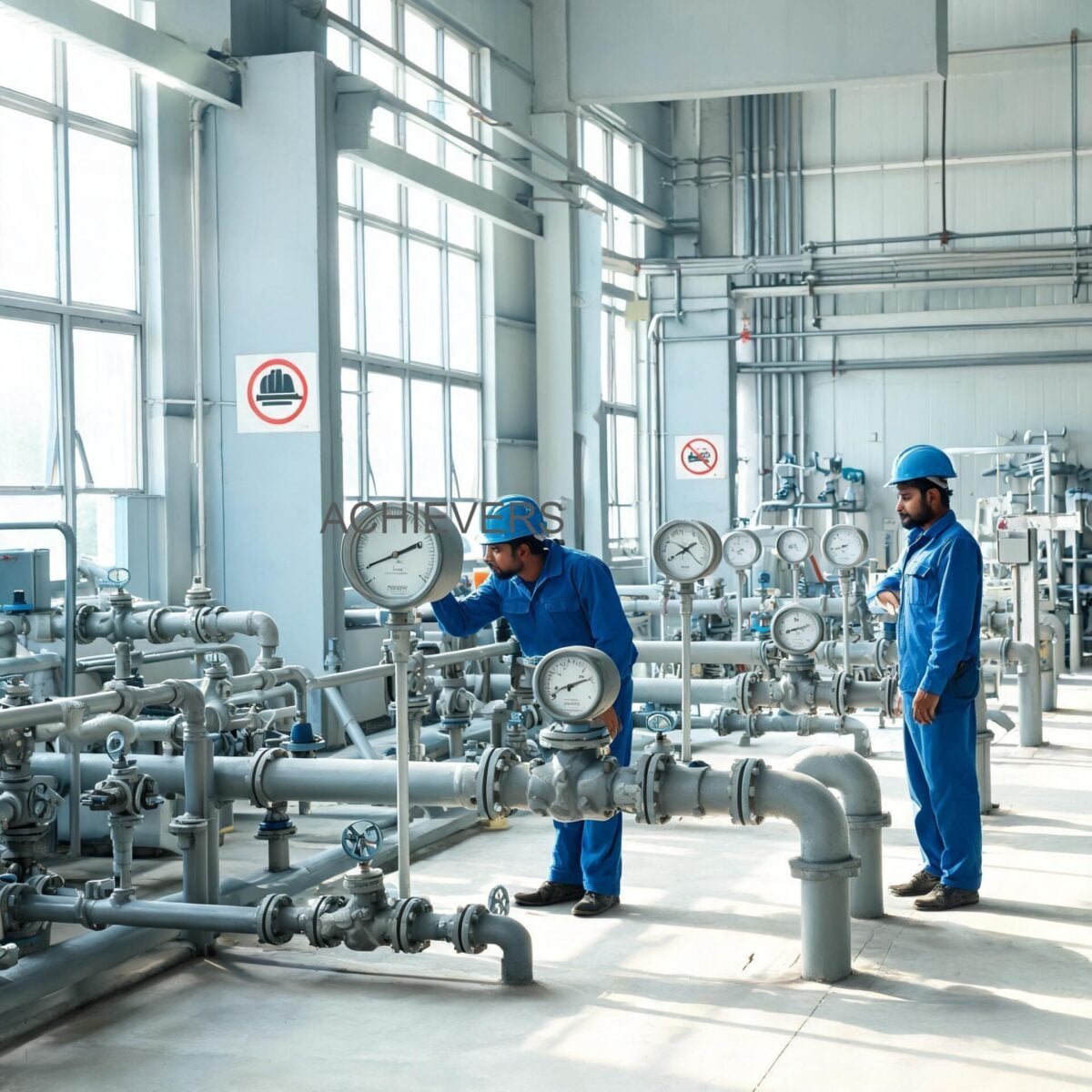
Operating flow instrumentation in India presents distinct geographical and infrastructural challenges that require proactive engineering adaptations.
1. High Ambient Temperatures:
During Indian summers, ambient temperatures in industrial yards frequently exceed 45°C. For digital variants like the CE-111 or CE-112, prolonged exposure to direct sunlight can bake the LCD displays and overheat the PCBs. Install physical sunshades over the meter installations. Furthermore, extreme heat alters the viscosity of the diesel, thinning it out and potentially increasing slippage. Ensure calibration is verified during peak summer and peak winter to account for fluid dynamic shifts.
2. Power Quality and Surges:
Indian industrial grids are notorious for voltage fluctuations, harmonics, and sudden surges—especially when heavy motors or furnaces trip in the plant. For meters connected to PLCs or batch controllers (via RS-485 or 4-20 mA outputs), ensure you utilize high-quality galvanic isolators and dedicated grounding. A power surge can easily fry the pulse transmitter, bringing batch automation to a halt.
3. Dust and Particulate Matter:
Mining, cement, and construction sites generate abrasive airborne dust. When performing maintenance, opening the meter body exposes the precision internals to this dust. Always erect a temporary clean-tent or windbreak before opening the measuring chamber on-site. The mechanical registers must have their weather covers closed securely to prevent dust from jamming the display gears.
4. Contaminated and Adulterated Fuel:
It is not uncommon to receive HSD shipments contaminated with water, rust from old tankers, or even deliberate adulteration (like mixing with kerosene or heavier oils). Since positive displacement meters are sensitive to dirt and changing viscosities, installing a two-stage filtration system (e.g., a primary 100-micron bulk filter followed by a 40-micron meter-protection strainer) is highly recommended. If water contamination is suspected, utilize a water-absorbing filter element to prevent internal corrosion of the meter body and bearings.
5. Monsoon Humidity and Moisture Ingress:
During the heavy monsoons, high humidity combined with temperature cycling causes condensation inside electrical enclosures. Ensure that all cable glands are strictly IP67/IP68 rated and properly potted. Use silica gel packets inside the terminal heads of digital meters, and replace them during your quarterly inspections.
By adhering to these engineering practices and understanding the fluid mechanics of volumetric entrapment, slippage, and pressure drop, plant managers can ensure their fluid measurement infrastructure operates with custody-transfer precision year after year.
FAQ
Q: Why does my meter show a higher volume than the actual fuel received in the tank?
A: This is almost always caused by air bubbles in the fluid stream being metered as liquid volume. Ensure your upstream air eliminator is functioning correctly and that your Fuel Transfer Pumps are not drawing in air through a suction leak.
Q: Can I use this meter for both heavy furnace oil and high-speed diesel?
A: While the meter can physically handle both, the vastly different viscosities will cause varying amounts of slippage. If you calibrate the meter for heavy oil, it will likely under-read when measuring lighter diesel. You must recalibrate when switching fluids for high accuracy.
Q: How frequently must we calibrate the meter to comply with Indian regulations?
A: If the meter is used for custody transfer or commercial billing, it must typically be verified and stamped annually as per the Legal Metrology Act of India. For internal plant monitoring, bi-annual proving against a master meter or prover tank is recommended.
Q: Does installing a finer mesh filter improve meter lifespan?
A: Yes, it protects the internal rotors from abrasion, but it also increases the pressure drop across the filter. You must monitor the differential pressure closely; a clogged fine filter will restrict flow and can cause cavitation or pump starvation.
Q: Is a straight pipe run required before the meter installation?
A: No. Unlike Turbine or Electromagnetic meters, Positive Displacement flow meters are insensitive to flow profile distortions. You do not need minimum straight pipe diameters upstream or downstream, making them ideal for cramped industrial skids.
Q: Our diesel often contains suspended water. Will this damage the meter?
A: Yes. While small amounts of water won't instantly stop the meter, prolonged exposure will cause internal corrosion, especially on bearings and gears. Use water-coalescing filters upstream to protect the meter's metallurgy.
Q: What is the main cause of sudden bearing failure in these meters?
A: Operating the meter beyond its maximum pressure drop specification, usually caused by pushing highly viscous fluids at excessive flow rates or operating with a heavily clogged upstream system. This exerts tremendous mechanical load on the bearings, leading to catastrophic failure.
To ensure you select the correct instrumentation for your specific site conditions, fluid viscosity, and automation requirements, contact our engineering team today. Please provide your exact fluid type, required flow rate range, operating pressure, and any specific output requirements (mechanical register vs. 4-20mA/RS-485), and we will configure the optimal metering solution for your plant.