
Accurate monitoring of industrial fuel consumption is no longer just a financial accounting exercise; it is a critical engineering requirement for thermal efficiency, emissions control, and predictive maintenance. Whether metering heavy fuel oil (HFO) into a megawatt-scale marine generator or monitoring light diesel oil (LDO) in a chemical plant boiler, the physics of fluid measurement determine the reliability of the data. For instrumentation engineers and plant managers, understanding the internal mechanics of Oil Flow Meters is the first step toward building audit-ready fuel management systems.
Unlike water or thin chemical solvents, petroleum-based liquids present unique rheological challenges. Their viscosities shift drastically with temperature, they entrain air during pump transfer, and they flow under varying pressure profiles. This technical deep-dive explains how positive displacement mechanics solve these challenges, where measurement accuracy is typically gained or lost in the field, and how to specify the correct instrumentation for rigorous industrial environments.
1. Working Principle: Positive Displacement Mechanics
To understand how positive displacement oil flow meters work for consumption monitoring, engineers must look past the electronic outputs and examine the fluid mechanics inside the measuring chamber. Positive Displacement (PD) meters operate by repeatedly entrapping a known, fixed volume of fluid and passing it from the inlet to the outlet.
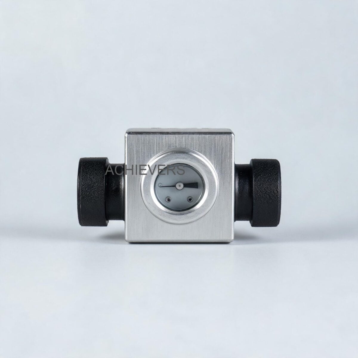
In high-density liquid applications, Lumen's volumetric rotary cylinder and oval gear designs are the industry standard. An oval gear meter utilizes two precisely machined, elliptical gears that rotate on perpendicular axes within a cavity. The fluid pressure differential between the inlet and outlet creates a driving torque on the gears.
During each full rotation, the gears sweep a highly precise volume of oil through the crescent-shaped gaps between the gear flanks and the outer chamber wall. Because the volume of this measuring chamber is geometrically fixed, the rotational frequency of the gears is directly proportional to the volumetric flow rate.
The governing engineering relationship for this mechanism is:
Q = V_s * N * E_v
Where:
- Q is the actual volumetric flow rate.
- V_s is the swept volume per revolution (a fixed geometric constant).
- N is the rotational frequency (measured in RPM or Hz).
- E_v is the volumetric efficiency (a dimensionless factor accounting for internal slip).
Because the moving parts are isolated by an effective magnetic coupling, only the gears and the measuring chamber are exposed to the metered fluid. This eliminates dynamic seal leaks and reduces mechanical drag, allowing the meter to operate continuously even under gravity-fed conditions with a head as low as 1 inch of oil.
2. Complete Technical Specifications
Specifying instrumentation requires exact operational parameters. The following table outlines the Oil Flow Meters specifications for manufacturers and EPC buyers, based on the mechanical and electronic architectures of Lumen Instruments' metering solutions.
| Technical Parameter | Specification / Rating | Engineering Notes |
| :— | :— | :— |
| Line Size Range | 006 mm to 150 mm (1/4" to 6") | Small sizes (15-25mm) for consumption; large (40-150mm) for unloading/draw-off. |
| Typical Accuracy | ± 0.5% of reading | Consistent across calibration levels. |
| High-Precision Accuracy | ± 0.2% of reading | Available on request for custody transfer or high-fidelity audits. |
| Repeatability | Better than 0.02% | Critical for batching and continuous consumption tracking. |
| Pressure Drop | Ultra-low (Operates under 1" head) | Suitable for gravity-fed unloading without auxiliary pumping. |
| Connection Types | Screwed or Flanged (DIN ND10) | Screwed available up to 25mm; Flanged exclusively for 40mm to 150mm. |
| Filtration Requirement | Integrated / Upstream Strainer | Minimum 100 mesh required to protect gear clearances from particulates. |
| Electronics Interface | Magnetic Coupling | Zero moving seals exposed to the environment. |
| Standard Warranty | 1 Year | Extended 2-year warranty available on demand. Spare parts readily available. |
| Display Orientation | 360-degree rotatable (90º steps) | Register top can be removed and rotated for easy reading in complex piping runs. |
| Calibration Units | Liters, US Gallons, UK Gallons | Stepless alignment system ensures continuous accuracy. |
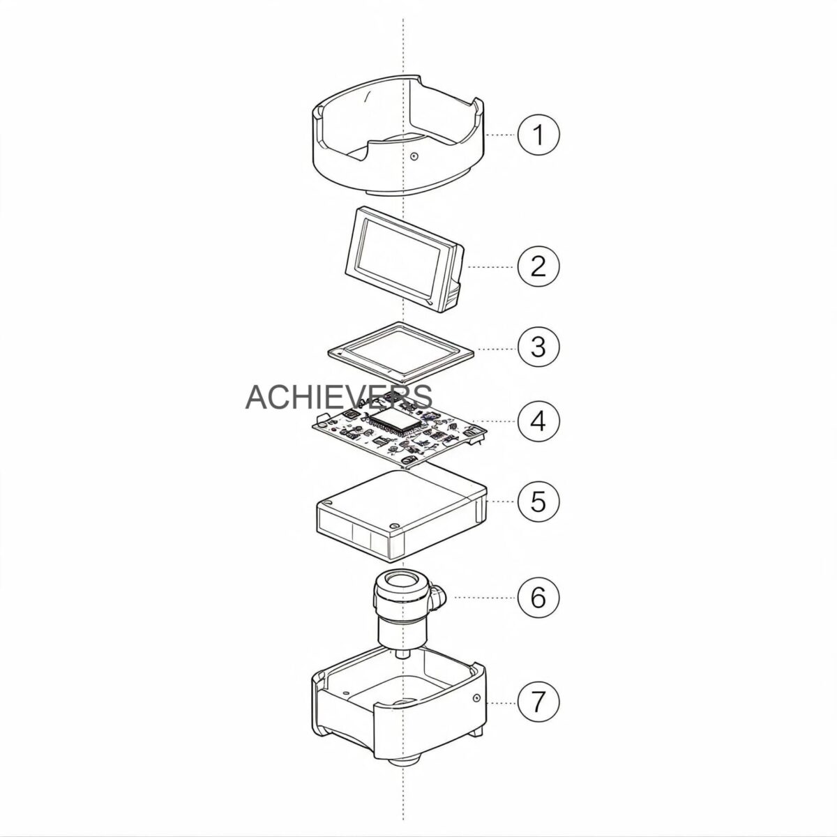
For engineers integrating these meters into larger SCADA or DCS networks, Oil Flow Meters can be equipped with robust electronic modules. The PG 1 Pulse Generator runs on a 12 to 24 VDC power supply, converting mechanical gear rotation into a pulse signal transmitted via a 3-core cable. This feeds directly into the TF 200 Remote Totalizer or the BTF 200 Combined Batching Unit, which utilizes an FI converter to generate an industry-standard 4 – 20 mA analog signal for advanced process control.
3. Performance Characteristics: Slip, Viscosity, and Error Sources
While PD meters are the most accurate technology for hydrocarbon liquids, instrumentation engineers must understand the phenomenon of "slip" to master industrial oil flow meter accuracy limits slip pulsation aeration explained in practical contexts.
The Physics of Slip Flow
Slip refers to the microscopic volume of fluid that bypasses the measuring chamber by leaking through the mechanical clearance gaps between the rotors and the casing. Because metal-to-metal contact would cause instant wear and failure, a tolerance of a few micrometers is engineered into the meter.
The rate of slip leakage is governed by a variation of the Hagen-Poiseuille equation for flow between parallel plates. The key engineering takeaway is that slip flow is inversely proportional to the dynamic viscosity of the fluid and directly proportional to the differential pressure across the meter.
When metering heavy oils like furnace oil or HFO, the high viscosity seals the clearance gaps, reducing slip to near zero and driving volumetric efficiency (E_v) to 99.9%. However, if the oil is heated excessively (lowering its viscosity) or if the meter is used for very light solvents, the slip increases, and the meter will slightly under-register the true flow.
Dealing with Aeration and Entrained Gas
Positive displacement meters measure total fluid volume—they cannot distinguish between liquid oil and trapped air. When unloading petroleum products via high-speed pumps, the suction side often draws in atmospheric air, creating a two-phase flow. If this air enters the measuring chamber, it is recorded as oil, leading to massive financial losses in custody transfer and artificially inflated consumption data. The installation of a mechanical air release system (air eliminator) upstream of the meter is an absolute engineering necessity for pumped offloading applications.
Pulsation and Mechanical Wear
Reciprocating pumps or heavily unbalanced gear pumps can introduce severe hydraulic pulsations into the piping network. While Oil Flow Meters are sturdily constructed, extreme pressure spikes can stress the magnetic coupling or cause micro-cavitation near the gear teeth. Installing pulsation dampeners and ensuring the meter size is correctly matched to the maximum flow rate (rather than just the pipe diameter) prevents premature mechanical wear.
4. Technology Comparison and Decision Matrix
Many facilities default to installing whatever flow technology is currently in the warehouse, leading to disastrous measurement errors. Because oil is typically non-conductive, Electromagnetic Flow Meters cannot be used. This leaves engineers choosing between Positive Displacement, Turbine, and Coriolis technologies.
Below is a comparative engineering analysis to aid in selection.
| Parameter | Positive Displacement (Oval Gear) | Turbine Flow Meters | Coriolis Mass Flow |
| :— | :— | :— | :— |
| Primary Measurement | Volumetric | Velocity | Mass |
| Viscosity Tolerance | Excellent (Accuracy improves with high viscosity) | Poor (Viscosity drastically alters the flow profile and K-factor) | Excellent |
| Straight Pipe Requirement | Zero (0D upstream / 0D downstream) | High (10D upstream / 5D downstream) | Zero |
| Pressure Drop | Very Low (Suitable for gravity head) | Moderate | High (Due to U-tube geometry) |
| Accuracy Profile | ±0.5% to ±0.2% | ±1.0% (highly dependent on stable viscosity) | ±0.1% to ±0.2% |
| Capital Cost (CAPEX) | Moderate | Low | Extremely High |
| Best Application | Diesel generators, boilers, gravity draw-off tanks | Low-viscosity, continuous high-velocity fluids | Custody transfer at refineries |
When to Use Positive Displacement: A Decision Matrix
Use PD Oil Flow Meters when:
- The application involves varying viscosities (e.g., day/night temperature swings affecting outdoor diesel lines).
- The system operates under a gravity head (where Coriolis or Turbine would cause too much restriction).
- Piping geometry is constrained (PD meters require zero straight pipe runs, making them ideal for cramped generator enclosures).
- You require mechanical backup (the mechanical dial retains the totalized reading even during a total plant power failure).
Conversely, if metering highly abrasive fluids with heavy suspended solids, the tight tolerances of a PD meter may jam. In such rare slurry-like conditions, alternative non-intrusive technologies must be evaluated.
5. Material Compatibility and Process Integration
The longevity of a flow meter is dictated by the chemical compatibility of its wetted parts. Standard meters utilize cast iron or aluminum bodies with stainless steel or specialized resin rotors.
| Process Fluid | Compatibility | Engineering Notes |
| :— | :— | :— |
| Light Diesel Oil (LDO) | Excellent | Provides ideal lubricity for continuous operation. |
| High-Speed Diesel (HSD) | Excellent | Standard calibration media; highly accurate. |
| Furnace Oil (FO) | Excellent | High viscosity seals clearances, yielding ±0.2% accuracy. |
| Hydraulic & Lube Oils | Excellent | Perfect for lubrication flow monitoring on heavy machinery. |
| Vegetable / Cooking Oils | Excellent | Food-grade materials must be specified for hygienic compliance. |
| Water / Aqueous Acids | Not Recommended | Lack of lubricity will cause rapid gear wear; risk of corrosion. |
| Abrasive Slurries | Incompatible | Particulates will jam the precision micro-clearances. |
| Gasoline / Petrol | Acceptable | Requires ATEX/hazardous area certifications; slip is slightly higher due to low viscosity. |
6. Global Installation Standards and Commissioning Procedure
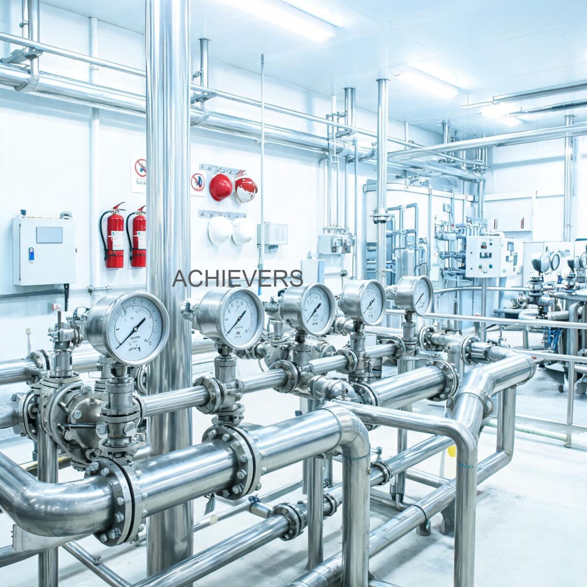
An instrumentation engineer knows that a meter with 0.2% accuracy in the lab can easily suffer a 5.0% error in the field if installed incorrectly. Whether configuring systems in Europe, the Middle East, or utilizing Oil Flow Meters in India for boiler and generator fuel oil measurement, the fundamental fluid dynamics remain identical. To achieve audit-ready precision, follow this standardized installation procedure:
- Pipeline Flushing: Before integrating the meter, the entire pipeline must be vigorously flushed to remove welding slag, rust scale, and thread tape. Do not flush the line through the newly installed meter.
- Strainer Installation: Install a Y-strainer or basket strainer with a minimum of 100 mesh exactly upstream of the meter. Particulate contamination is the leading cause of rotor jamming.
- Bypass Loop Construction: Install the meter within a bypass loop featuring isolation valves and a bypass valve. This simplifies subsequent servicing and calibration without forcing a plant shutdown.
- Air Eliminator Integration: If the fluid is being pumped (especially from the bottom of an emptying tank), install an air release framework upstream of the strainer to vent entrained gases.
- Meter Orientation: Mount the meter such that the rotor shafts are strictly in the horizontal plane. While the volumetric rotary cylinder design is forgiving, vertical shaft orientation in gear meters can cause uneven thrust bearing wear over years of operation.
- Dial Alignment: Once bolted to the DIN ND10 flanged connections (or screwed ends for smaller lines), remove and rotate the mechanical register to the most ergonomic cardinal position for operator reading.
FAQ
Q: Can these meters measure highly viscous fluids like heated Heavy Fuel Oil (HFO)?
A: Yes. Positive displacement technology actually performs better with highly viscous fluids. The thick oil acts as a dynamic seal between the gear lobes and the measuring chamber, reducing slip leakage and often improving the overall accuracy to ±0.2%.
Q: Do I need straight pipe runs upstream and downstream of the meter?
A: No. Unlike turbine or ultrasonic flow meters, Positive Displacement Flow Meters do not rely on a conditioned, fully developed flow profile. You can install valves, elbows, or reducers immediately adjacent to the meter flanges without degrading measurement accuracy.
Q: How frequently should the meter be recalibrated?
A: For standard internal consumption monitoring on boilers and generators, field verification and calibration are recommended every 12 to 18 months. If the meter is subjected to highly abrasive fluids or operates 24/7 at maximum flow rates, an annual inspection of the measuring chamber is advised.
Q: What causes the meter's mechanical register to stop turning while oil is still flowing?
A: This typically indicates that the internal shear pin has broken or the magnetic coupling has decoupled due to a rotor jam (usually caused by debris bypassing a damaged strainer). The fluid may continue to force its way past the jammed gears (severe slip), but the meter requires immediate maintenance and strainer cleaning.
Q: Will the meter operate if there is a total power failure at the plant?
A: Yes. The base mechanical meter utilizes a gear-driven mechanical counter and requires absolutely no external power source. Only the optional electronic pulse generators (PG 1) and remote totalizers (TF 200) require a 12-24V power supply.
Q: Are these meters suitable for gravity-fed tank draw-offs where there is no pump?
A: Absolutely. Lumen oil flow meters have an exceptionally low pressure drop and can operate effectively under just 1 inch of oil head. For gravity unloading, 80mm size meters are heavily recommended to allow sufficient volumetric flow without restricting the line.
Q: Can I connect the meter to our plant's centralized DCS?
A: Yes. By equipping the meter with a PG 1 Pulse generator and a BTF 200 FI converter, the mechanical rotation is translated into an industry-standard 4 – 20 mA analog signal, allowing for remote totalization, batch controlling, and real-time flow rate indication on standard process control interfaces.
To ensure you select the correct instrumentation for your thermal infrastructure, contact our engineering team to discuss your specific requirements. Please provide your target application, maximum and minimum flow rates, pipeline diameter, fluid type, and operating temperature so we can specify the exact Oil Flow Meters supplier for industrial applications tailored to your facility's operational demands.