
Measuring fuel consumption on modern heavy-duty diesel engines requires overcoming a fundamental hydraulic challenge: diesel engines do not consume all the fuel drawn by the transfer pump. To cool and lubricate the fuel injection system, engines draw a massive surplus of fuel, returning the unburned excess back to the tank. Standard single-line flow measurement provides gross flow, not actual consumption. To capture precise usage data for performance auditing, emissions reporting, or theft prevention, industrial operators rely on dual-sensor Fuel Consumption Meters.
Understanding the engineering mechanics behind these differential systems is critical for plant managers, marine engineers, and fleet procurement heads operating across global environments. From offshore power generation to high-altitude mining operations, selecting the correct meter involves balancing positive displacement mechanics, netting logic, thermal dynamics, and telematics integration. This technical deep-dive explores the physics, operational boundaries, and installation requirements of high-accuracy fuel consumption measurement.
1. Working Principle: How Fuel Consumption Meters Operates
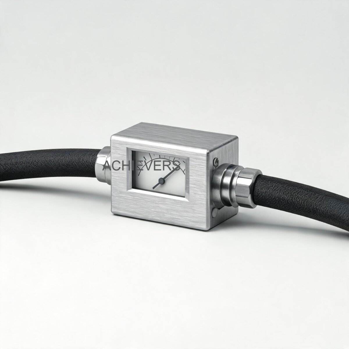
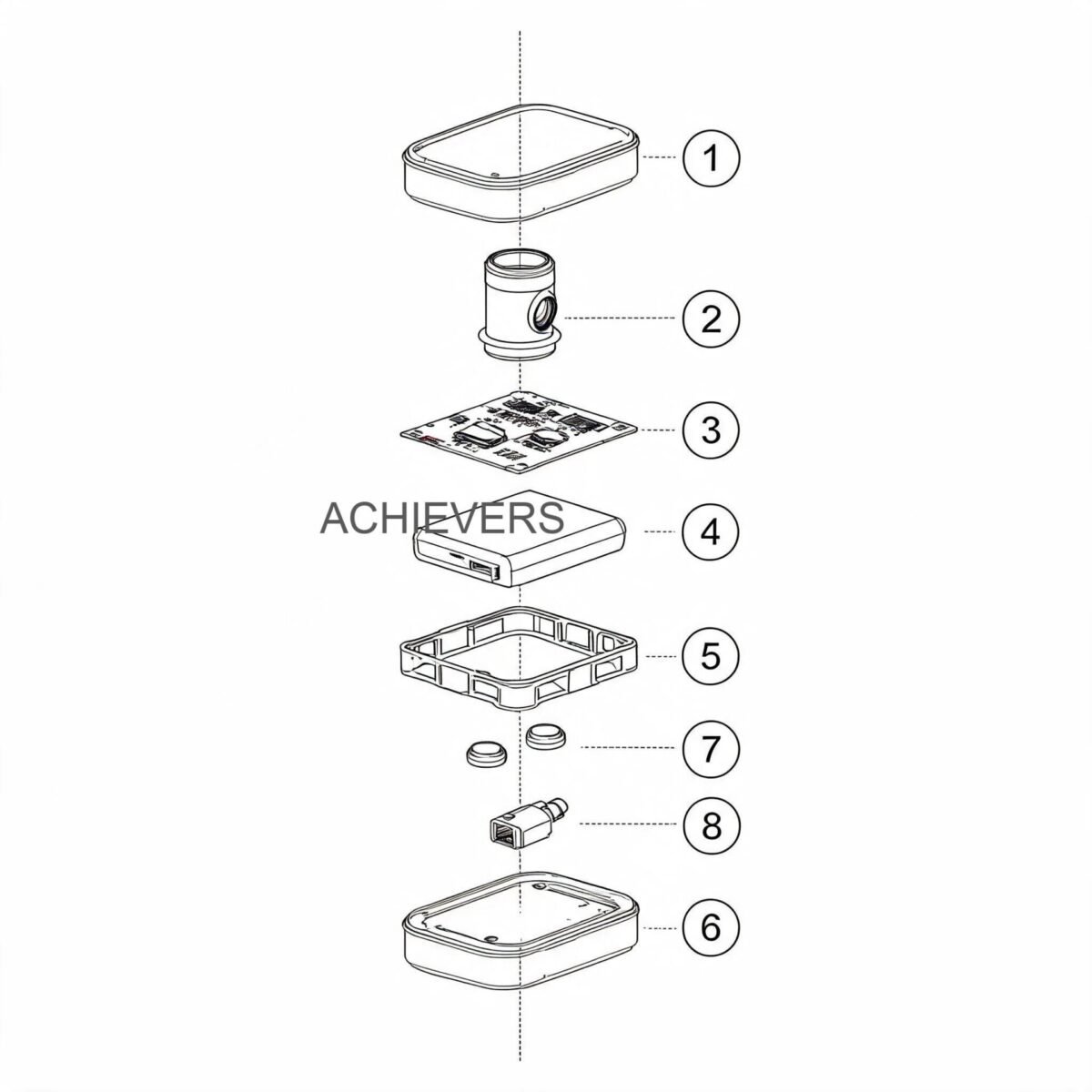
The architecture of industrial Fuel Consumption Meters consists of three core components: a supply line flow sensor, a return line flow sensor, and a centralized flow calculator (microprocessor).
To achieve high accuracy in viscous, pulsating diesel flow, the sensors utilize a Positive Displacement (PD) principle—specifically, oval gear technology. Inside the sensor chamber, two precision-machined, anodized aluminum oval gears interlock. As fuel pressure forces the fluid through the chamber, the gears rotate. Because the geometry of the measuring chamber and the gears is fixed, every full rotation displaces an exact, continuous, and verifiable volume of liquid (the swept volume).
Magnets embedded in the gear rotors trigger a stationary sensor (typically a Hall-effect sensor or reed switch) mounted outside the fluid boundary. This generates a high-resolution pulse output proportional to the exact volume of fuel passing through the line.
The netting logic is calculated continuously by the digital flow calculator. The microprocessor measures the total diesel quantity supplied to the engine (Parameter A) and deducts the excess hot diesel returning from the engine back to the tank (Parameter B). The resulting difference gives the absolute net fuel consumption (Parameter C).
The calculation executed is: Net Consumption = A – B
Because diesel flow in injection systems is highly pulsating, velocity-based meters (like turbines) suffer from inertia-induced over-reading. Oval gear PD mechanics mechanically lock the fluid volume, eliminating pulsation errors and ensuring that the measured volume is independent of flow profile or Reynolds number fluctuations.
2. Complete Technical Specifications
Proper specification requires matching the engine's horsepower rating to the correct sensor swept volume. The data below outlines the technical specifications for industrial Fuel Consumption Meters designed for heavy machinery, marine applications, and power generation.
| Parameter | Specification | Engineering Notes |
| :— | :— | :— |
| Measurement Principle | Positive Displacement (Oval Gear) | Differential dual-sensor configuration. |
| Sensor Accuracy | 0.1% Full Scale Deflection (FSD) | Applies to standard horizontal/vertical installation position. |
| System Accuracy (Net) | 0.5% of actual consumption | Combined error limit of the A – B netting calculation. |
| Sensing Component | Aluminum Anodized Oval Gear | Viscosity independent; highly resistant to diesel particulate wear. |
| Body Material | Aluminum Anodize | Lightweight, high tensile strength, excellent corrosion resistance. |
| Power Supply | 5 Vdc to 24 Vdc (Up to 29 Vdc peak) | Directly compatible with onboard 12V/24V engine battery systems. |
| Signal Outputs | RS-485 / RS-232 / Pulse Output | Ready for integration with GPS/GPRS telematics and SCADA systems. |
| Filtration Requirement | Y-Type Fuel Strainer integrated | Mandatory to prevent gear jamming from tank sludge or debris. |
| Model CE-006 Capacity | Up to 200 HP Diesel Engines | Suitable for light commercial vehicles and small gensets. |
| Model CE-008 Capacity | 200 HP to 400 HP Diesel Engines | Standard for medium-duty trucks, school buses, and earth moving equipment. |
| Model CE-012 Capacity | 400 HP to 1000 HP Diesel Engines | Specified for heavy infrastructure equipment and small marine vessels. |
| Model CE-020 Capacity | 1000 HP to 2500 HP Diesel Engines | Designed for high-capacity industrial diesel generators and mining haulers. |
| Model CE-025 Capacity | 1500 HP to 2000 HP Diesel Engines | Specialized high-flow variant for continuous duty applications. |
| Display Metrics | Inline, Return, Net Qty, and Time | Units configurable in Liters, Gallons, or Cubic Meters. |
3. Performance Characteristics and Error Sources
While oval gear sensors offer robust mechanical measurement, dual-line netting introduces specific thermodynamic and hydraulic variables that instrumentation engineers must account for to maintain the 0.5% system accuracy limit.
Thermal Expansion and Density Shifts
Diesel fuel expands as it heats up. The volumetric coefficient of thermal expansion for standard diesel is approximately 0.00083 per degree Celsius. Fuel drawn from the tank (Supply A) may be at an ambient 25 C. After circulating through the high-pressure injection pump and cylinder heads, the unburned fuel (Return B) absorbing engine heat may return at 65 C or higher.
Because the return fuel is hotter, its density decreases, and its physical volume expands. If a volumetric meter simply subtracts Return Volume from Supply Volume without accounting for this expansion, it will falsely calculate a lower net consumption rate. High-end systems mitigate this either through tightly constrained mechanical calibration tolerances for specific temperature bands, or by utilizing flow calculators that integrate RTD temperature sensors to apply a dynamic mass-conversion formula:
True Mass Consumption = (Volume A x Density at Temp A) – (Volume B x Density at Temp B)
Pulsation and Mechanical Vibration
Diesel injection pumps create severe hydraulic shockwaves. Oval gears inherently resist this better than Positive Displacement Flow Meters based on vane or piston designs, but severe vibration can induce false pulses in magnetic pick-ups. Installing the sensors utilizing vibration-damping mounts prevents structural resonance from interfering with the Hall-effect sensors.
Air Entrainment
If the primary fuel pump draws air due to a micro-leak in the suction line, the supply sensor will measure the air-fuel mixture as pure liquid volume, causing a massive over-reporting of fuel consumed. Ensuring absolute zero-leak fittings prior to the supply sensor is structurally critical.
4. Technology Comparison and Decision Matrix
To understand why oval gear positive displacement is the global standard for engine fuel consumption, we must compare it against other technologies utilized in industrial fluid measurement.
Technology Comparison Table
| Feature | Oval Gear (Positive Displacement) | Turbine Flow Meters | Coriolis Mass Meters | Electromagnetic Meters |
| :— | :— | :— | :— | :— |
| Measurement Type | Direct Volumetric | Velocity-based inferential | Direct Mass | Velocity-based (conductive) |
| Pulsating Flow Response | Excellent (mechanically locked) | Poor (rotor inertia causes over-run) | Excellent (fast response) | N/A (Diesel is non-conductive) |
| Viscosity Independence | Very High (accuracy improves with viscosity) | Low (requires constant viscosity) | Very High | N/A |
| Pressure Drop | Moderate (ΔP drives the gears) | Low | Moderate to High | Zero |
| Capital Cost (Dual Sensor) | Moderate | Low | Extremely High | N/A |
| Ideal Application | Diesel engines, generators, telematics | Steady state transfer, bulk loading | Custody transfer, refineries | Water, slurries, acids |
Decision Matrix: When to Use Dual-Sensor Oval Gear Meters
Choose this technology if:
- You are measuring fuel consumption on active, running engines where unburned fuel is returned to the tank.
- The system experiences pulsating flow from mechanical injection pumps.
- The operating environment involves varying ambient temperatures altering fuel viscosity.
- You require direct RS-485 or pulse outputs to feed remote GPS tracking or GPRS asset management telematics.
- You need to prevent fuel theft (the closed-loop calculation makes siphoning immediately visible on the data log).
Consider alternative technologies if:
- You are merely transferring fuel from a bulk storage tank to a vehicle (use standard Diesel Flow Meters).
- You require certified custody-transfer mass measurement regardless of extreme temperature gradients (use Coriolis, bearing in mind the massive cost multiplier).
5. Materials and Chemical Compatibility
Reliability in harsh environments (mining, marine, remote telecom towers) dictates strict material selection. Fuel Consumption Meters utilize carefully engineered alloys to prevent degradation from high-sulfur diesel, biodiesel blends, and marine gas oil (MGO).
| Fluid / Chemical | Compatibility Status | Engineering Notes |
| :— | :— | :— |
| Standard Diesel (ULSD) | Excellent | Primary design fluid. Provides ideal lubricity for gears. |
| Marine Gas Oil (MGO) | Excellent | Fully compatible with marine grade fuels. |
| Biodiesel (B20 to B100) | Good | Confirm seal compatibility (Viton/FKM recommended). |
| Heavy Fuel Oil (HFO) | Moderate | Requires heating jackets to maintain pumpable viscosity. |
| Kerosene / Aviation Fuel | Good | Lower lubricity increases gear wear over long term; requires recalibration. |
| Water / Coolant | Incompatible | Causes immediate galvanic corrosion and gear seizure. |
| Corrosive Acids / Solvents | Incompatible | Aluminum anodized body will degrade rapidly. |
| Petrol / Gasoline | Incompatible | Extreme fire hazard (ATEX compliance required) and lacks lubricity. |
6. Installation, Calibration, and Verification
Achieving the rated 0.5% system accuracy requires stringent adherence to mechanical piping standards. The flow sensors are precision instruments; poor installation will degrade accuracy, increase pressure drop, and potentially starve the engine of fuel.
Engineered Installation Procedure
- Verify System Pressure and Flow Limits: Audit the engine's fuel pump capacity. Ensure the maximum flow rate of the supply line does not exceed the upper limit of the selected flow sensor (e.g., matching a CE-012 model to a 1000 HP engine).
- Install Pre-Filtration: Mount the required Y-type fuel strainer directly upstream of the supply sensor. Machined oval gears have micron-level clearances; weld slag, tank rust, or debris will cause catastrophic gear lock.
- Mount Sensors Horizontally: Secure both the supply and return sensors in a horizontal pipe run where possible. If vertical installation is required, ensure the flow direction is upwards to keep the chamber full of liquid and purge trapped air.
- Isolate from Excessive Heat: Do not mount the return sensor directly against the exhaust manifold. While the aluminum body withstands heat, extreme localized temperatures can degrade the digital calculator electronics and warp sensor seals.
- Implement Bypass Valves (Optional but Recommended): Install a three-valve bypass manifold around the sensors. In the event of an unexpected meter blockage, the bypass ensures the engine can continue running without fuel starvation, critical for emergency diesel generators and marine propulsion.
- Wire the RS-485 / Pulse Outputs: Connect the onboard power (5 Vdc to 24 Vdc) from the engine battery system. Terminate the RS-485 signal wire to your local PLC, SCADA, or GPS telematics modem, ensuring proper shielding against electromagnetic interference (EMI) from the alternator.
- Perform Field Air Purge: Before initiating the digital calculator, crank the engine or run the priming pump to bleed all atmospheric air from the supply and return lines. Entrained air is the leading cause of false consumption spikes during commissioning.
Calibration and Field Verification Note
Fuel Consumption Meters are factory calibrated on test benches using fluids of known viscosity. Over years of heavy-duty operation, mechanical wear on the gear teeth can cause slight fluid slippage, shifting the K-factor.
To verify accuracy in the field without dismantling the piping, engineers can perform a known-volume weight test. Disconnect the return line and route it into a certified volumetric proving tank or load cell, whilst drawing fuel from an external, measured day-tank. Run the engine for 30 minutes at 75% load. The mathematically derived formula:
Calculated System Error = [(Day Tank Volume Consumed – Proving Tank Volume Returned) – Meter Displayed Net Consumption] / Actual Net Volume Consumed x 100.
If the error exceeds 0.5%, adjust the flow calculator's pulse-per-liter (PPL) variable.
FAQ
Q: Why can't I just use a single flow meter on the supply line?
A: Diesel engines operate a closed-loop fuel system. The transfer pump supplies vastly more fuel than the injectors actually burn, using the surplus to cool and lubricate the injection system before returning it to the tank. A single meter on the supply line will over-report actual consumption by up to 300%.
Q: How does the temperature difference between supply and return fuel affect accuracy?
A: Hot return fuel has a lower density and occupies a larger volume than cool supply fuel. High-quality fuel consumption netting logic accounts for standard thermal expansion. In extreme temperature differentials, uncompensated volumetric subtraction will result in a slight under-reporting of total fuel consumed.
Q: What is the maintenance interval for oval gear flow sensors?
A: Oval gear meters are self-lubricating via the diesel fuel itself. The primary maintenance is inspecting and cleaning the upstream Y-strainer every 500 to 1,000 operational hours. The gears and bearings typically provide 5 to 7 years of continuous service before requiring recalibration or rebuild.
Q: Can this system definitively prove if fuel is being stolen from the vehicle?
A: Yes. Because the Fuel Consumption Meter calculates the exact net fuel burned by the engine, any discrepancy between the engine's documented consumption and the physical drop in the fuel tank level immediately highlights siphoning or tank theft.
Q: How do I integrate the meter with my existing fleet tracking software?
A: The flow calculator is equipped with RS-485, RS-232, and pulse outputs. These digital protocols connect directly to standard GPS/GPRS telematic modems, allowing real-time fuel consumption rates to be transmitted to cloud-based dashboards alongside geographic vehicle data.
Q: Are these meters affected by vibrations from heavy earth-moving equipment?
A: Positive displacement oval gear meters are highly resilient to mechanical vibration because the fluid is physically encapsulated between the gear teeth. However, severe shock loads can damage the electronic circuit boards, so utilizing rubber isolation mounts during installation on heavy mining equipment is recommended.
Q: What happens if air enters the fuel line?
A: Air entrainment destroys measurement accuracy. The positive displacement gears will rotate and measure the pocket of air exactly as if it were liquid fuel. Operators must ensure zero air leaks on the suction side of the fuel pump to maintain the 0.5% accuracy rating.
If you are upgrading your power generation infrastructure, managing an offshore marine fleet, or deploying remote heavy machinery, accurate fuel tracking is non-negotiable for operational profitability. Contact our engineering team today with your engine horsepower rating, fluid characteristics, and site conditions to specify the exact Fuel Consumption Meters and communication outputs required for your application.