
In industrial fluid management, the cost of unplanned flow measurement failure extends far beyond the price of a replacement instrument. When volumetric measurement devices degrade, facilities face compounding losses: undocumented fuel consumption, batching inaccuracies, and measurement disputes that erode operational margins. For positive displacement (PD) flow technologies, sustaining metrological precision is entirely dependent on meticulous, schedule-driven preventive maintenance.
Because Diesel Flow Meters operate by repeatedly entrapping fluid within moving mechanical clearances, they inherently rely on tight physical tolerances. Over time, the abrasive nature of unfiltered media, pressure spikes, and continuous rotational friction will wear down sealing surfaces and bearings. This degradation leads to "slippage"—the phenomenon where unmeasured fluid bypasses the measuring chamber—directly compromising accuracy. Implementing a rigorous preventive maintenance schedule is the only engineering solution to control slippage, sustain accuracy, and maximize the operational lifecycle of your measurement instrumentation.
Product Overview and Critical Wear Components
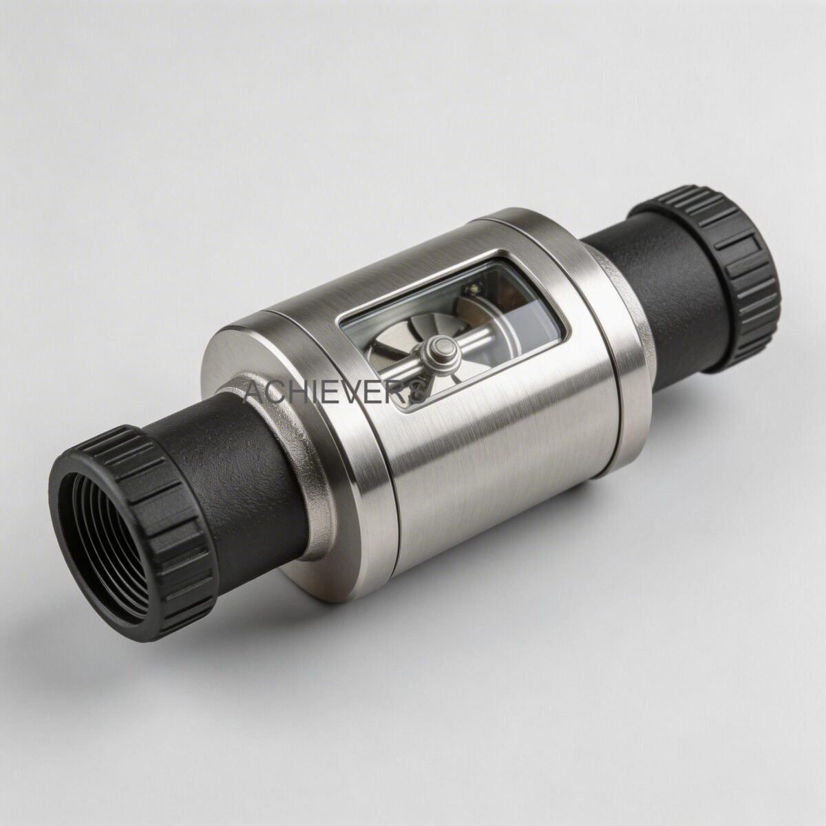
Diesel Flow Meters utilizing positive displacement innovation measure the exact volumetric flow of liquids by isolating the fluid into discrete, known volumes. The mechanism can be conceptualized as repeatedly filling and emptying a calibrated basin. The internal geometry often consists of rotating gears, oscillating pistons, or nutating discs that form moving dynamic seals with the meter body.
Because the measurement relies on these rotating parts maintaining extremely tight tolerances, any wear directly impacts performance. While these meters excel at handling viscous fluids like High-Speed Diesel (HSD) and marine diesel—where higher viscosity actually improves accuracy by sealing internal clearances and reducing slippage—they remain susceptible to mechanical wear from particulate contamination.
Critical wear components include:
- Rotors and Measuring Chambers: Susceptible to scoring from abrasive particles, which increases clearance volumes and subsequent slippage.
- Bearings (Journal and Thrust): Essential for maintaining rotor alignment. Bearing wear allows lateral rotor movement, altering the dynamic seal. Furthermore, operating the meter beyond its maximum allowable pressure drop causes premature, sometimes catastrophic, bearing failure.
- Dynamic Seals and Gaskets: Ensure fluid does not bypass the measuring chamber. Degradation leads to internal leakage.
- Mechanical Registers and Signal Transmitters: The mechanical linkages or magnetic pickups that translate rotation into volumetric pulses or digital readouts can suffer from environmental ingress or mechanical fatigue.
Model Specifications and Variants
Based on standard industrial configurations, here is a specification breakdown of the common Diesel Flow Meters variants utilized in heavy-duty applications:
| Model Variant | Register Type | Output Options | Typical Flow Range | Max Operating Pressure | Key Feature |
| — | — | — | — | — | — |
| Achievers CE-113 | Mechanical | Local Readout | 20 – 120 LPM | 10 Bar (150 PSI) | High-visibility local display, independent of power |
| Achievers CE-110 | Electronic | Digital Display | 10 – 100 LPM | 20 Bar (300 PSI) | Compact footprint, battery operated |
| Achievers CE-111 | Electronic | Pulse / Digital | 20 – 200 LPM | 20 Bar (300 PSI) | High-accuracy digital calibration |
| Achievers CE-112 | Advanced Transmitter | 4-20 mA, Pulse, RS-485 | 50 – 500 LPM | 40 Bar (600 PSI) | SCADA/PLC integration ready, remote monitoring |
Technology Comparison and Decision Matrix
No single flow measurement technology is universally applicable. Selecting the correct meter requires evaluating fluid properties, flow profiles, and site conditions. Below is a comparative engineering analysis between Positive Displacement Diesel Flow Meters, Turbine Flow Meters, and Electromagnetic Flow Meters.
| Parameter | Positive Displacement (Diesel Flow Meters) | Turbine Flow Meters | Electromagnetic Flow Meters |
| — | — | — | — |
| Primary Working Principle | Direct volumetric entrapment | Velocity measurement via rotor speed | Faraday's Law of Electromagnetic Induction |
| Best Suited Media | Clean, viscous fluids (Diesel, Oils, HSD) | Clean, low-viscosity liquids and gases | Conductive liquids (Water, Slurries, Wastewater) |
| Viscosity Dependency | Accuracy increases with higher viscosity | Accuracy decreases heavily with viscosity | Independent of viscosity |
| Upstream Piping Requirements | None (Zero straight run required) | High (typically 10D upstream, 5D downstream) | Moderate (typically 5D upstream, 3D downstream) |
| Pressure Drop | Moderate to High (increases with viscosity) | Moderate (increases with square of flow rate) | Zero (unobstructed flow tube) |
| Typical Accuracy | +/- 0.2% to 0.5% of reading | +/- 0.5% to 1.0% of reading | +/- 0.2% to 0.5% of reading |
"When to Use" Decision Matrix
| Application Scenario | Recommended Technology | Engineering Rationale |
| — | — | — |
| High Viscosity Hydrocarbons (e.g., Marine Diesel, Fuel Oils) | Positive Displacement | Fluid viscosity naturally seals rotor clearances, reducing slippage and achieving superior low-flow accuracy. |
| Conductive Corrosive Chemicals / Water-Based Slurries | Electromagnetic | Unobstructed flow path prevents clogging. Inert liners (PTFE/PFA) handle extreme corrosives. |
| High-Velocity, Low-Viscosity Solvents / Water | Turbine | Highly repeatable velocity measurement at high Reynolds numbers; lower pressure drop than PD for thin fluids. |
| Space-Constrained Installations (No Straight Pipe Run) | Positive Displacement | PD meters measure volume directly and are immune to asymmetric velocity profiles caused by upstream valves or elbows. |
Preventive Maintenance Schedule
To mitigate the risk of excessive pressure drops and bearing failure, a structured preventive maintenance protocol is mandatory. The following schedule is designed for Diesel Flow Meters operating in continuous industrial environments.
| Task | Frequency | Responsible | Est. Time | Notes |
| — | — | — | — | — |
| Visual External Inspection | Daily | Plant Operator | 5 mins | Check for casing leaks, register housing integrity, and abnormal mechanical noise. |
| Differential Pressure Check | Weekly | Maintenance Tech | 10 mins | Monitor pressure drop across the meter. An increasing drop indicates bearing wear or a clogged upstream strainer. |
| Upstream Strainer Cleaning | Monthly | Maintenance Tech | 30 mins | Diesel heavily relies on clean fluid. Debris scoring the measurement chamber permanently damages accuracy. |
| Air Eliminator Vent Check | Monthly | Maintenance Tech | 15 mins | Ensure air vents are operating. Air pockets are measured as liquid, causing positive measurement errors. |
| Seal and Gasket Inspection | Quarterly | Reliability Engineer | 45 mins | Inspect static seals for weeping. High ambient temperatures degrade elastomeric seals over time. |
| Calibration / Proving Check | Bi-Annually | Metrology Team | 2 hours | Verify accuracy against a known master meter or volumetric prover. Calculate current slippage rates. |
| Mechanical Register Lubrication | Bi-Annually | Maintenance Tech | 20 mins | If applicable, lubricate mechanical gearing assemblies to prevent binding. |
| Electrical Terminal & Battery Check | Bi-Annually | I&E Technician | 15 mins | Clean RS-485/4-20mA terminals on digital models to prevent signal loss; replace batteries in local displays. |
| Bearing & Rotor Inspection | Annually | Specialist/OEM | 3 hours | Full teardown to measure rotor clearances. Non-lubricating fluids increase bearing wear significantly. |
| System Flush / Winterization | Annually | Maintenance Tech | 1 hour | Flush lines if fluid properties change seasonally to prevent waxy buildup in cold weather. |
Step-by-Step Procedures for Key Tasks
Procedure 1: Upstream Strainer and Air Eliminator Maintenance
Abrasive particulate matter and entrained gases are the two most destructive elements for positive displacement metering accuracy. Running dirty fluids will score the sealing surfaces, while air bubbles artificially inflate the volumetric reading.
- Isolate the Metering Run: Close the upstream and downstream block valves to completely isolate the flow meter, strainer, and air eliminator assembly.
- Depressurize the Line: Safely bleed off internal system pressure using the designated bleed valves. Ensure fluid is drained into an appropriate environmental containment vessel.
- Access the Strainer Basket: Unbolt the strainer housing cover. Carefully remove the O-ring or housing gasket and inspect it for swelling or chemical degradation.
- Extract and Clean the Mesh: Remove the stainless steel strainer mesh. Clean it using an appropriate solvent and a soft bristle brush. Never use wire brushes that could deform the mesh sizing.
- Inspect for Metal Shavings: Examine the debris inside the strainer. The presence of metallic flakes may indicate upstream pump cavitation or impending pump failure.
- Service the Air Eliminator: Open the top of the air eliminator housing. Inspect the float mechanism and the reed valve. Ensure the float moves freely and the venting orifice is entirely free of waxy diesel residues.
- Reassembly: Reinstall the cleaned strainer basket. Apply a light film of compatible lubricant to the new housing gasket, and torque the cover bolts in a crisscross pattern to the manufacturer's specified rating.
- System Priming: Slowly open the upstream valve to allow the housing to fill and vent atmospheric air. Once fluid bleeds continuously without sputtering, fully open both valves and inspect for leaks under operating pressure.
Procedure 2: Slippage Evaluation and Calibration Check
Slippage is the fluid that passes through the clearances of the meter without being measured. It is fundamentally governed by the pressure differential across the meter, the clearance dimensions, and the dynamic viscosity of the fluid.
Engineering Principle:
Flow Rate of Slippage = (Pressure Differential * Clearance Dimension cubed) / (Constant * Fluid Viscosity * Sealing Length)
This relationship dictates that as viscosity increases, slippage decreases. Conversely, as bearing wear increases the physical clearance, slippage increases exponentially (cubed).
- Set Up Volumetric Prover: Connect a certified volumetric proving tank or a master meter downstream of the operational flow meter.
- Ensure Temperature Stability: Circulate fluid through the system until the temperature of the diesel reaches a steady state. Volume changes drastically with temperature (approx. 0.1% per degree Celsius for diesel).
- Establish Test Flow Rates: Plan to run calibration batches at three distinct points: 20%, 50%, and 80% of the meter's maximum rated flow capacity.
- Run the Low-Flow Batch: Run the fluid into the prover at the 20% flow rate. Record the indicated volume on the meter register and the actual volume in the prover.
- Calculate Meter Factor:
- Analyze Low-Flow Data: In PD meters, slippage is most pronounced at very low flow rates. If the meter factor is unacceptably high at the 20% mark but normal at 80%, it is a definitive indicator of internal clearance wear.
- Adjust the Calibrator: If the meter has a mechanical calibrator or a digital K-factor parameter, adjust it based on the weighted average of the meter factors across all three flow rates.
- Seal and Document: Once the calibration falls within the required +/- 0.5% tolerance, wire-seal the register to prevent tampering and log the new K-factor in the facility's asset management system.
Meter Factor = Actual Prover Volume / Indicated Meter Volume.
On-Site Spare Parts to Stock
Supply chain disruptions can turn a minor seal failure into a multi-day shutdown. For critical flow measurement applications, instrumentation engineers must maintain a localized inventory of consumable and high-wear components.
| Part | Type / Material | Recommended Stock Qty | When to Replace |
| — | — | — | — |
| Strainer Mesh Baskets | 100 Mesh Stainless Steel | 2 per active meter | When mesh is deformed, punctured, or permanently clogged with wax. |
| Housing O-Rings & Gaskets | Viton / PTFE | 4 sets per meter | Any time a housing is opened for inspection or maintenance. |
| Journal Bearings | Carbon / Tungsten Carbide | 1 set per 3 meters | During annual teardown, or if pressure drop increases by 15% above baseline. |
| Air Eliminator Floats | Stainless Steel | 1 per eliminator | If float loses buoyancy or the linkage mechanism becomes physically worn. |
| Digital Output Transmitters | Hall Effect Sensor / Pickup | 1 per facility | If pulse output becomes erratic or fails entirely while mechanical gears spin normally. |
| Rotor/Measuring Chamber Assemblies | Aluminum / Stainless Steel | 1 per 5 meters | Only upon catastrophic failure, scoring, or when calibration limits can no longer be met. |
Diagnosing Maintenance-Related Failures
Even with rigorous schedules, varying process conditions can induce sudden faults. Utilizing symptom-based diagnostics allows maintenance teams to rapidly trace issues back to missed preventive care or process anomalies.
| Failure Symptom | Most Likely Root Cause | Missed Maintenance Task | Corrective Action |
| — | — | — | — |
| Meter Under-Registers Flow (High Meter Factor) | Internal wear causing excessive fluid slippage | Failure to clean upstream strainer, allowing abrasive wear | Rebuild measuring chamber and replace bearings/rotors. |
| Meter Over-Registers Flow (Low Meter Factor) | Entrained air bubbles being measured as liquid | Neglecting air eliminator inspection | Clean and repair air eliminator float and vent valve. |
| High Differential Pressure Across Meter | Upstream strainer clogged, or bearings seizing | Weekly DP check; Monthly strainer cleaning | Clean strainer immediately; inspect bearings if pressure drop persists. |
| Erratic or Dropped Digital Pulses | Failing magnetic pickup or loose terminal wiring | Bi-annual electrical terminal inspection | Tighten wiring, shield against EMI, or replace Hall-effect sensor. |
| Complete Mechanical Seizure (Meter stops) | Catastrophic bearing failure or solid object jammed | Strainer mesh rupture due to lack of cleaning | Complete teardown required. Clear debris, replace damaged wetted parts. |
| Fluid Weeping from Register Housing | Dynamic seal degradation on the output shaft | Quarterly seal and gasket inspection | Isolate meter and replace packing gland or dynamic shaft seals. |
Extending Service Life in Extreme Global Conditions
Industrial measurement instruments operate in environments far removed from laboratory conditions. To sustain accuracy across diverse, harsh global sites—from offshore platforms to arid mining facilities—engineers must modify standard maintenance protocols.
High Ambient Temperatures & Humidity
In regions experiencing intense heat or tropical humidity, the localized environment around the meter degrades external components rapidly. High temperatures accelerate the vulcanization and hardening of elastomeric seals. Upgrade standard NBR gaskets to high-temperature Viton or Kalrez. Additionally, in monsoon or highly humid areas, ensure that electronic registers (like the RS-485 variants) are housed in IP67/NEMA 4X enclosures and utilize silica desiccant packs to prevent condensation on internal circuit boards.
Dusty and Abrasive Environments
In mining or heavy manufacturing sectors, airborne dust poses a severe threat to mechanical registers. Ensure that mechanical displays are fitted with heavy-duty polycarbonate covers. If fine particulate matter frequently contaminates the fluid supply, upgrade the upstream filtration system from a simple inline strainer to a duplex filtration bank, allowing operators to switch and clean filters without halting fluid transfer.
Corrosive or Offshore Environments
Saline air in offshore installations causes rapid galvanic corrosion on standard aluminum or cast-iron meter bodies. Specify flow meters with 316L stainless steel wetted parts and marine-grade epoxy coatings for the exterior housing. Fasteners should be frequently inspected and coated with anti-seize compounds to ensure the meter can actually be opened for maintenance when required.
Managing Non-Lubricating Liquids
While diesel has excellent natural lubricity, some facilities use the same PD meters for chemical batching or light solvents. Non-lubricating fluids vastly increase bearing friction. If utilizing these meters outside of standard hydrocarbon fuels, specify carbon-graphite or ceramic bearings, and reduce the maximum allowable flow rate by 20% to prevent thermal expansion and seizing of the rotors.
FAQ
Q: Why does the meter register flow when no fluid is actually moving through the pipe?
A: This is known as "phantom flow" and is typically caused by severe line vibration affecting the mechanical register, or electromagnetic interference (EMI) generating false pulses in the digital transmitter. Ensure the meter is isolated from pump vibrations and sensor cables are properly shielded.
Q: How frequently do I need to recalibrate a positive displacement flow meter?
A: For custody transfer or high-value batching, calibration proving should be conducted every 6 months. For general inventory monitoring, an annual calibration check is sufficient, provided the differential pressure remains stable.
Q: Does changes in fluid temperature affect the meter's accuracy?
A: The meter itself measures actual volume perfectly regardless of temperature. However, the fluid's volume expands and contracts with temperature changes. For precise mass accounting, a temperature compensator or flow computer must be used to calculate standard volume at 15°C (60°F).
Q: Can I use these meters for highly viscous fluids like heavy fuel oil (HFO)?
A: Yes. Positive displacement technology actually performs better with highly viscous fluids because the thick liquid effectively seals the mechanical clearances, drastically reducing internal slippage. Ensure the system can handle the increased pressure drop.
Q: What causes sudden, catastrophic failure of the rotors?
A: Sudden failure is almost exclusively caused by thermal shock (rapid introduction of hot fluid into a cold meter causing unequal expansion), hydraulic hammer (valves closing too fast), or large foreign debris bypassing a ruptured strainer.
Q: Is straight piping required upstream of a positive displacement meter?
A: No. Unlike turbine or ultrasonic technologies, positive displacement meters are immune to swirling or asymmetrical flow profiles. They can be installed directly after a 90-degree elbow or a control valve without sacrificing measurement accuracy.
Q: How do I select the right micron rating for the upstream strainer?
A: Follow the manufacturer's specification, which is generally dictated by the internal clearance of the meter. Typically, an 80 to 100 mesh (approx. 150-180 microns) is standard for industrial diesel applications to prevent scoring of the chamber while allowing normal flow.
To ensure your facility selects the optimal measurement technology, contact our engineering team with your specific requirements. Please provide the intended product model, expected minimum and maximum flow rates, fluid viscosity, and details regarding your site's operating temperature and pressure conditions so we can specify the exact instrumentation for your application.