
The financial penalty of an unplanned fluid transfer failure extends far beyond the cost of replacement hardware. When diesel transfer systems go offline, entire operations—from heavy earth-moving machinery in open-pit mines to emergency backup generators in data centers—grind to a halt. While Fuel Transfer Pumps are engineered for rugged, off-grid reliability, they are not immune to the fundamental laws of fluid dynamics, friction, and thermal stress. Treating these critical assets as "install and forget" equipment inevitably leads to diminished flow rates, cavitation, seal degradation, and premature motor burnout.
To sustain optimal volumetric efficiency and protect the direct-current (DC) permanent magnet motors driving these systems, plant engineers and maintenance managers must implement highly structured preventive checks. A rigorous maintenance protocol mitigates the effects of fluid contamination, dead-heading, and thermal overload. This guide delivers an instrumentation-level approach to maintaining Fuel Transfer Pumps, detailing suction integrity analysis, strainer servicing, bypass valve diagnostics, and duty-cycle management to ensure your fluid transfer infrastructure operates at peak precision worldwide.
1. Product Overview and Critical Wear Components
Industrial Fuel Transfer Pumps for diesel and kerosene are predominantly self-priming, positive displacement rotary vane pumps. Unlike centrifugal pumps, which rely on fluid velocity and struggle with aeration, positive displacement vane pumps generate distinct fluid cavities, allowing them to pull a strong suction vacuum (typically 2 to 4 meters of lift) and handle varied fluid viscosities.
The core architecture consists of an eccentric cast iron pump body finished with anti-corrosion paint, housing a sintered steel rotor. Slotted within this rotor are acetal resin vanes. As the rotor turns (up to 2800 RPM in standard 12V/24V models), centrifugal force pushes the vanes outward against the internal cam ring, trapping fluid and sweeping it from the inlet to the discharge port.
Because these internal components rely on tight mechanical tolerances to prevent fluid slip, they are highly susceptible to particulate damage and abrasive wear.
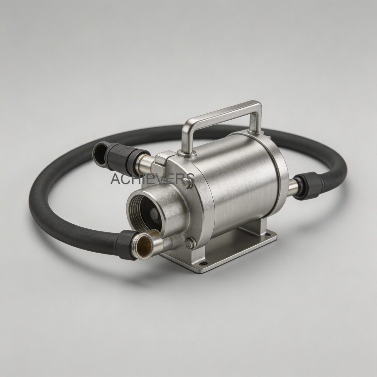
Mechanical and Electrical Specifications
Understanding the exact operational limits of your specific hardware is the foundation of preventive maintenance. Operating outside these parameters accelerates wear exponentially.
| Specification Parameter | CE-40DC Series | CE-70-A-DC Series | CE-80-DC Series |
| :— | :— | :— | :— |
| Pump Mechanism | Rotary Vane | Rotary Vane | Rotary Vane |
| Max Flow Rate | 40 L/min | 70 L/min | 80 L/min (System max up to 120 L/min) |
| Operating Voltage | 12V / 24V DC | 12V / 24V DC | 12V / 24V DC |
| Current Draw | Low (Specific to load) | 4A | 44A (12V) / 21A (24V) |
| Inlet / Outlet Ports | 3/4 Inch | 3/4 Inch | 1 Inch |
| Max Suction Lift | 2-4 meters | 2-4 meters | 2-4 meters |
| Max Head Pressure | ~10 meters | 10 meters | 10-15 meters |
| Motor Duty Cycle | 30 Minutes Intermittent | 30 Minutes Intermittent | 30 Minutes Intermittent |
| Motor Protection | IP55 | IP55 | IP55 |
| Rotor / Vanes | Sintered Steel / Acetal Resin | Sintered Steel / Acetal Resin | Sintered Steel / Acetal Resin |
Technology Comparison: Transfer Pump Topologies
To optimize your fueling infrastructure, it is critical to understand how rotary vane DC pumps compare to other transfer technologies available in the global market.
| Parameter | DC Rotary Vane (Target Technology) | AC Centrifugal | Pneumatic Diaphragm (AODD) | Gear Pump (Positive Displacement) |
| :— | :— | :— | :— | :— |
| Best For | Mobile fleet fueling, diesel, kerosene | Bulk water/chemical transfer, high volume | Highly abrasive fluids, explosive zones (ATEX) | High-viscosity oils, heavy lubricants |
| Self-Priming | Excellent (Dry prime up to 2m) | Poor (Requires flooded suction) | Excellent | Good (But prefers wet prime) |
| Viscosity Limit | Low to Medium (Diesel, light oils) | Low (Water-like fluids only) | High (Can handle slurries) | Very High (Gear oils, resins) |
| Flow Consistency | Smooth, continuous flow | Smooth, dependent on head pressure | Pulsating flow | Smooth, highly accurate |
| Shear Sensitivity | Medium shear | High shear | Low shear | High shear |
| Maintenance Need | Vane replacement, strainer checks | Mechanical seal replacement | Diaphragm / check valve replacement | Gear clearance checks |
"When to Use This Technology" Decision Matrix
- IF you require mobile, off-grid fuel transfer from a vehicle battery (12V/24V) AND the fluid is diesel or kerosene AND you need self-priming capabilities, THEN USE DC Rotary Vane Fuel Transfer Pumps.
- IF you are transferring highly viscous gear oils or bunker fuel, THEN USE Positive Displacement Gear Pumps.
- IF you are emptying bulk storage tanks at a fixed facility with access to grid power and require flow rates exceeding 500 L/min, THEN USE AC Centrifugal Transfer Pumps.
- IF you need highly precise custody-transfer measurement of the fluid being moved, pair your transfer pump with Positive Displacement Flow Meters to eliminate flow profile dependencies.
—
2. Preventive Maintenance Schedule
Implementing a robust Fuel Transfer Pumps preventive maintenance checklist for industrial diesel transfer systems is the most effective way to guarantee the longevity of the IP55-rated motor and the sintered steel rotor. DC transfer pumps operate on a strict 30-minute intermittent duty cycle. Failure to enforce this operational limit, alongside neglecting strainer maintenance, causes 85% of premature equipment failures.
| Task | Frequency | Responsible Party | Est. Time | Engineering Notes & Tolerances |
| :— | :— | :— | :— | :— |
| Visual Leak Inspection | Daily / Pre-use | Operator | 2 Mins | Inspect cast-iron body joints, 3/4" or 1" inlet/outlet threads, and pump-to-motor shaft seal for diesel weepage. |
| Duty Cycle Verification | Daily | Operator | N/A | Ensure motor is never run past its 30-minute thermal limit to protect IP55 stator windings. |
| Inlet Strainer Cleaning | Weekly (or 5,000 L) | Maintenance Tech | 10 Mins | Built-in strainer must be cleared of rust/silica. Blockage causes cavitation and destroys acetal resin vanes. |
| Suction Line Vacuum Test | Monthly | Maintenance Tech | 15 Mins | Verify suction lift remains within 2-4 meters. Excessive vacuum indicates suction blockage or collapsed hose. |
| Electrical Terminal Check | Monthly | Electrician | 10 Mins | Check 12V/24V DC terminal lugs for oxidation. Voltage drop increases amperage, causing motor overheating. |
| Bypass Valve Inspection | Bi-Monthly | Maintenance Tech | 20 Mins | Ensure internal bypass poppet is free-moving. A stuck valve will dead-head the pump, blowing seals. |
| Flow Rate / Efficiency Check | Quarterly | Reliability Eng. | 15 Mins | Clock the fill rate into a known volume. Flow degradation >15% indicates vane wear. |
| Vane & Rotor Inspection | Semi-Annually | Maintenance Tech | 45 Mins | Remove faceplate. Check acetal resin vanes for chipping or binding in the sintered steel rotor slots. |
| Motor Brush Inspection | Annually | Electrician | 30 Mins | Inspect carbon brushes on the DC motor for wear. Replace if length is below manufacturer minimum. |
| Bearing Lubrication | Factory Sealed | N/A | N/A | Bearings are factory lubricated for life; inspect only for excessive lateral shaft play or grinding noise. |
Engineering Formula: Tracking Volumetric Efficiency
To proactively detect internal wear before total failure occurs, instrumentation engineers track the pump's Volumetric Efficiency (Ev). As the acetal resin vanes wear down, high-pressure fluid slips back into the low-pressure suction zone (internal slip).
Volumetric Efficiency (%) = (Actual Flow Rate / Theoretical Flow Rate) * 100
- Theoretical Flow Rate: Stated manufacturer spec (e.g., 80 L/min for CE-80-DC at 0 meters head).
- Actual Flow Rate: Measured output using a calibrated stopwatch and proving can, or verified via inline Diesel Flow Meters.
- Internal Slip Rate: Q_slip = Q_theoretical – Q_actual.
If volumetric efficiency drops below 80% (e.g., a 70 L/min pump is only delivering 55 L/min), the pump requires immediate faceplate removal to inspect the vanes and cam ring for grooving.
—
3. Step-by-Step Procedures for Key Tasks
Adhering to strict Fuel Transfer Pumps service procedure specifications for manufacturers and plant engineers ensures that maintenance does not inadvertently introduce contaminants or damage precision components.
Procedure 1: Built-In Strainer and Suction Filter Cleaning
The die-cast aluminum pump body features a built-in strainer designed to protect the rotor. A clogged strainer restricts fluid entry, causing the fluid to vaporize under low pressure (cavitation), which violently pits the metal rotor.
- Isolate Power: Disconnect the 12V or 24V DC electrical supply to ensure the pump cannot accidentally actuate.
- Depressurize the System: Open the manual or automatic dispensing nozzle to relieve any residual static head pressure in the discharge hose.
- Isolate Fluid: Close the suction and discharge isolation valves (if installed on the tank configuration).
- Access the Strainer Chamber: Locate the strainer access cap (usually a hex bolt or threaded cap near the inlet port). Use a properly sized wrench to prevent rounding the brass or aluminum fittings.
- Remove the Strainer Mesh: Carefully extract the cylindrical wire mesh screen. Inspect it against a light source to identify embedded particulates, biological growth (diesel bug), or rust.
- Clean the Mesh: Wash the strainer in a clean solvent bath (clean diesel or mild parts washer). Use a soft bristle brush. Never use compressed air blowing inward, and never use a wire brush, as this distorts the micron rating of the mesh.
- Inspect O-Rings: Examine the strainer cap O-ring for flattening, chemical swelling, or cracking. Replace if compromised to prevent air ingress on the suction side.
- Reassemble and Prime: Reinstall the strainer, tighten the cap to specified torque, open isolation valves, and briefly run the pump to purge air and re-establish prime.
Procedure 2: Internal Bypass Valve Inspection
The bypass valve protects the pump when the nozzle shuts off but the motor continues to run. It recirculates the fluid internally. If this valve sticks closed, the pump dead-heads, pressure spikes, and the motor burns out.
- Safety Lockout: Disconnect the power supply entirely.
- Locate Bypass Housing: Identify the bypass valve cap on the pump body (typically located on a parallel channel between the discharge and suction sides).
- Remove Cap and Spring: Unscrew the cap carefully; it is under spring tension. Remove the heavy-duty bypass spring.
- Extract the Poppet Valve: Remove the poppet valve mechanism. If it is stuck, do not use excessive force; use penetrating oil and gently work it loose.
- Inspect for Scoring: Check the sides of the poppet and the internal machined bore for scoring, which indicates particulate damage preventing smooth travel.
- Clean Components: Wipe down the poppet and bore with a lint-free shop rag and clean diesel.
- Test Spring Tension: Compress the spring manually. If it feels excessively soft or is physically shortened, it has lost its structural integrity and will bypass prematurely, reducing your flow rate. Replace if out of spec.
- Reassemble: Apply a light film of clean fluid to the poppet, insert it into the bore, align the spring, and thread the cap back on securely.
—
4. On-Site Spare Parts to Stock
To minimize downtime in remote industrial or agricultural applications, facilities should maintain a specific inventory of consumable components. Relying on "just-in-time" shipping for critical infrastructure is an unacceptable risk for high-stakes fueling operations.
| Part Description | Component Type | Recommended Stock Qty | Replacement Trigger |
| :— | :— | :— | :— |
| Acetal Resin Vanes | Wear Part / Consumable | 2 sets per pump | Volumetric efficiency drop >15%, physical chipping, or every 2 years. |
| Vitam / NBR O-Ring Kit | Sealing / Consumable | 3 sets per pump | Annual replacement, or whenever a housing/cap is opened. |
| Internal Strainer Mesh | Filtration | 1-2 per pump | Mesh becomes torn, permanently deformed, or irretrievably fouled. |
| Bypass Valve Spring | Mechanical | 1 per facility | Premature bypassing (low flow rate) or localized corrosion. |
| DC Motor Carbon Brushes | Electrical / Wear | 2 sets per pump | Motor draws high amperage, runs erratically, or brush length is worn past the indicator line. |
—
5. Diagnosing Maintenance-Related Failures
Even with a strong preventive protocol, external variables like fuel quality can induce faults. This Fuel Transfer Pumps supplier maintenance guide for B2B buyers empowers on-site personnel to rapidly trace symptoms back to their mechanical or electrical root causes.
| Failure Symptom | Most Likely Missed Maintenance Task | Engineering Root Cause & Corrective Action |
| :— | :— | :— |
| Motor runs but pumps no fluid | Vane inspection / Suction check | Vanes are jammed in the rotor slots due to swelling or debris. Clean rotor and replace vanes. Alternatively, severe suction air leak. |
| Flow rate is significantly reduced | Strainer cleaning / Bypass check | Clogged suction strainer is starving the pump, or a weakened bypass spring is allowing fluid to recirculate internally at low pressures. |
| Pump is excessively noisy / rattling | Suction line vacuum check | Pump is cavitating due to restricted suction (collapsed hose, clogged filter, or lift exceeding 4 meters). Clear suction path immediately. |
| Motor casing is dangerously hot | Duty cycle enforcement | The 30-minute intermittent duty cycle has been exceeded. Let motor cool completely. Prolonged heat destroys IP55 stator insulation. |
| Fluid leaking from pump shaft | Shaft seal inspection | Mechanical shaft seal has failed, likely due to prolonged dead-heading (running with nozzle closed) or abrasive particulate wear. |
| Pump blows DC fuses repeatedly | Electrical terminal & Brush check | Motor is pulling excessive current (locked rotor). Inspect for physical jamming in the pump head or shorted electrical windings. |
—
6. Extending Service Life in Harsh Environmental Conditions
Operating fuel transfer systems in extreme global environments—from sub-zero North American oil fields to dusty, high-humidity mining sites in the Asia-Pacific—requires adapting standard maintenance protocols to combat aggressive environmental stressors. Global maintenance planners often reference rigorous benchmarks, such as the Fuel Transfer Pumps maintenance schedule in India for industrial fueling operations, to design protocols capable of withstanding extreme ambient heat and monsoonal humidity.
High Ambient Temperatures & Duty Cycles:
The 30-minute duty cycle is calibrated for standard atmospheric conditions. In environments where ambient temperatures exceed 40°C (104°F), the die-cast aluminum housing loses its ability to dissipate heat effectively. Plant engineers should derate the duty cycle to 20 minutes of continuous operation, followed by an equal or longer cooling period, to protect the permanent magnet stator.
High-Particulate & Dusty Environments:
Fine airborne silica can bypass poorly sealed fuel tank breathers, entering the diesel. When this abrasive dust is sucked through the pump, it scores the cast-iron pump body and sintered steel rotor. In mining and agricultural setups, it is critical to install heavy-duty, moisture-absorbing desiccant breathers on the bulk storage tanks to pre-filter the air entering the system.
Cold Weather Viscosity Changes:
While these pumps easily handle standard diesel and kerosene, low temperatures cause diesel to gel, drastically increasing its kinematic viscosity. Pumping high-viscosity, gelled diesel places immense torque strain on the DC motor and can cause the internal bypass valve to force open prematurely. Ensure winterized diesel blends are used, or utilize tank heaters to keep fluid viscosity within the pump’s design specifications.
Voltage Drops in Field Applications:
Because these pumps run on 12V or 24V DC systems, they are highly sensitive to voltage drops caused by long cable runs. If a pump is mounted 10 meters away from the vehicle battery with inadequate gauge wire, the voltage drop will cause the motor to overdraw current (Amps) to compensate, leading to rapid overheating. Always use manufacturer-specified wire gauges for extensions.
—
FAQ
Q: Can I run this transfer pump continuously if I install external cooling fans?
A: No. The motors are strictly designed for a 30-minute intermittent duty cycle. Even with external air movement, the internal thermal mass of the permanent magnet stator and windings will accumulate heat rapidly, leading to insulation failure and permanent motor damage.
Q: What is the maximum suction lift, and what happens if I exceed it?
A: The recommended maximum suction lift is 2 to 4 meters, depending on the fluid's specific gravity and viscosity. Exceeding this limit lowers the Net Positive Suction Head available (NPSHa) below what the pump requires, leading to severe cavitation, which sounds like marbles passing through the pump and will destroy the internals.
Q: Can these DC vane pumps be used to transfer gasoline or aviation fuel?
A: Absolutely not. These specific pumps are designed for diesel, kerosene, and light fuel oils. Pumping highly volatile fluids like gasoline requires ATEX/UL-listed explosion-proof equipment. Using standard DC pumps for gasoline presents a severe fire and explosion hazard.
Q: Why does the bypass valve exist if the pump has an automatic shut-off nozzle?
A: The bypass valve is a critical safety mechanism. When the automatic nozzle clicks closed, the pump motor continues spinning. Without the bypass valve to recirculate the fluid internally, the trapped fluid would instantly create massive hydraulic pressure, bursting seals, hoses, or stalling and burning out the DC motor.
Q: How often should I replace the acetal resin vanes?
A: Vane wear depends heavily on fluid cleanliness and runtime. In clean diesel applications with proper strainer maintenance, vanes can last several years. However, you should inspect them annually or replace them immediately if you notice a 15% or greater drop in volumetric efficiency.
Q: Does the orientation of the pump installation matter?
A: The versatile design allows for flexible installation on "L" shaped tanks and various mounts. However, it is best practice to install the pump horizontally to ensure even wear on the factory-lubricated bearings and to maintain optimal alignment of the bypass poppet valve gravity assist.
Q: Why is my pump drawing higher amperage than stated in the specifications?
A: High current draw (e.g., pulling more than 44A on a 12V CE-80-DC model) typically indicates mechanical binding. Check for swollen vanes, a clogged discharge filter causing high head pressure, or failing motor bearings. Alternatively, check for low supply voltage, which forces the motor to draw more amps to generate the required wattage.
If you are experiencing flow degradation or are planning an upgrade to your industrial fueling infrastructure, proactive equipment selection is critical. Contact our technical team today with your required flow rate, fluid type, and site power constraints so we can engineer a Fuel Transfer Pump configuration perfectly matched to your operational demands.