
Selecting the correct fluid handling equipment is a critical engineering decision that directly impacts plant uptime, safety, and operational expenditure. Among fluid handling solutions, Fuel Transfer Pumps represent a vast and often misunderstood category. Buyers frequently struggle to parse through marketing claims to determine whether an electric rotary vane pump or a pneumatic diaphragm pump is the optimal choice for their specific industrial constraints. This comprehensive engineering guide resolves that ambiguity, providing a deep dive into electric vs pneumatic fuel transfer pumps for diesel specifications, performance limits, and integration requirements.
Whether you are an instrumentation engineer outfitting a remote mining site, a plant manager upgrading an automated batching system, or a procurement head looking to source from a reliable industrial fuel transfer pump supplier, understanding the underlying mechanics of these pumps is essential. The right technology ensures consistent flow profiles, mitigates cavitation risks, and aligns with strict international hazardous area regulations (ATEX, IECEx, API). In this guide, we will evaluate both architectures head-to-head, helping you determine the best fuel transfer pump for diesel bowser and tank farm applications based on empirical data, fluid dynamics, and lifecycle costs.
1. Overview of Fuel Transfer Pumps Family
The core function of these Fuel Transfer Pumps is to safely and efficiently move hydrocarbons—ranging from low-viscosity gasoline and kerosene to heavier diesel fuels and lubricants—from storage vessels to process lines or dispensing endpoints. Depending on the available plant utilities, safety classifications, and required duty cycles, engineers typically choose between two dominant architectures: Electric Positive Displacement (Rotary Vane) pumps and Pneumatic (Air-Operated Double Diaphragm) pumps.
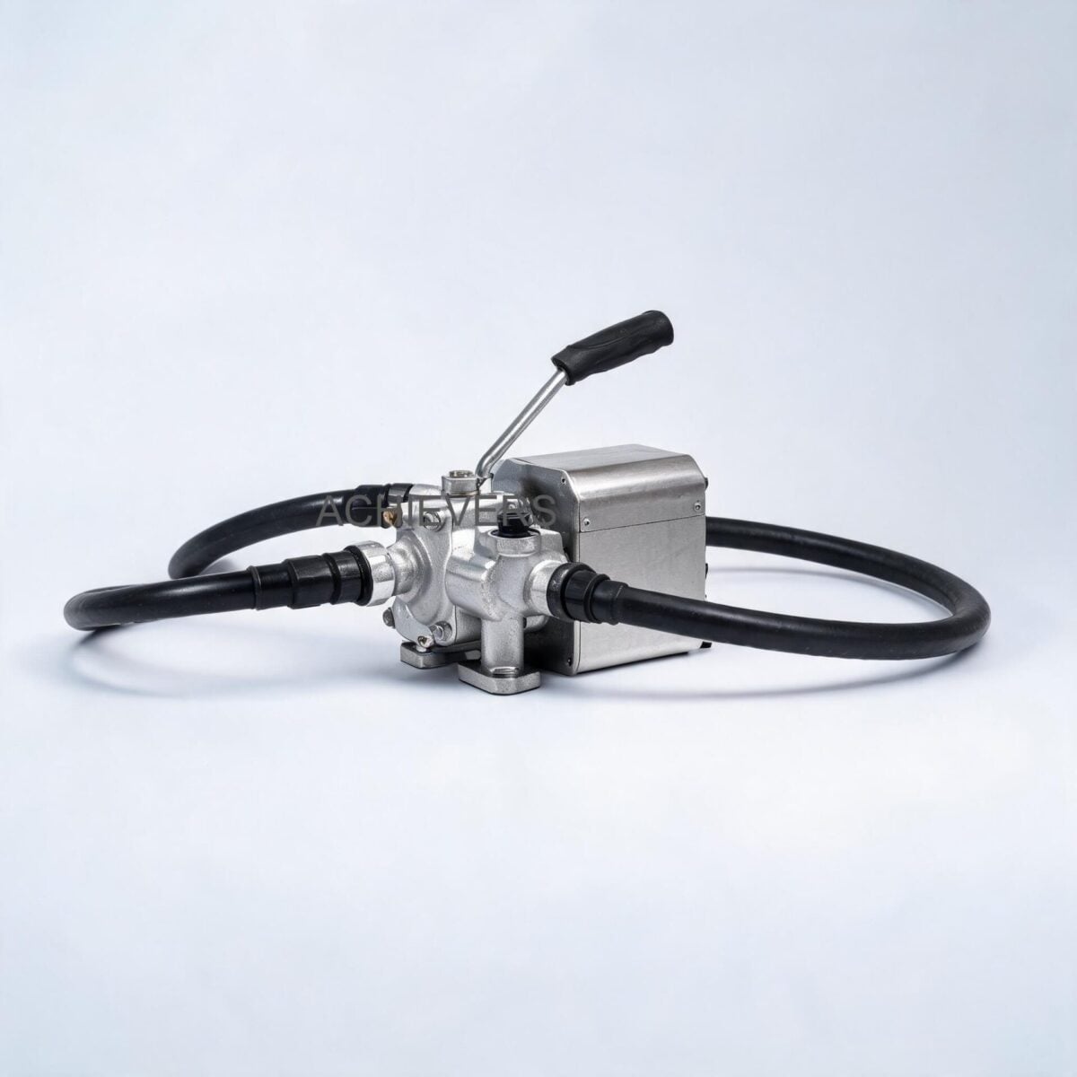
Electric direct-current (DC) and alternating-current (AC) Fuel Transfer Pumps are the backbone of mobile and stationary fuel dispensing. The electric variants detailed in this engineering analysis utilize a positive displacement, self-priming gear or rotary vane mechanism. For instance, high-performance DC models feature a cast iron pump body finished with anti-corrosion paint, a sintered steel rotor, and acetal resin vanes. The integration of acetal resin ensures low friction, self-lubrication, and excellent chemical resistance to petroleum-based fluids. These pumps frequently feature built-in bypass valves to prevent dead-heading, integral strainers to protect the rotor from particulate ingress, and overload protectors to shield the motor (typically rated at IP55) during adverse conditions.
Conversely, pneumatic transfer pumps rely entirely on compressed air to actuate internal diaphragms. Because they lack electrical components, pneumatic pumps are inherently intrinsically safe, making them an attractive option for highly explosive environments (ATEX Zone 0 and 1) where electrical isolation would otherwise require heavy, expensive explosion-proof enclosures.
2. Head-to-Head Specification Comparison
When evaluating these technologies, engineers must look beyond basic flow rates and examine the nuanced specifications that dictate long-term reliability. The following table compares three standard electric DC configurations (based on exact product specifications) against a standard equivalent pneumatic benchmark.
| Specification / Feature | Option A: Electric CE-40DC | Option B: Electric CE-70-A-DC | Option C: Electric CE-80-DC | Option D: Standard Pneumatic (AODD) |
| :— | :— | :— | :— | :— |
| Operating Power | 12V / 24V DC Direct Current | 12V / 24V DC Direct Current | 12V / 24V DC (44A / 21A draw) | Compressed Air (2-7 Bar) |
| Max Flow Rate | 40 Liters/Min | 70 Liters/Min | 80 Liters/Min | Varies by air supply (up to 120 L/Min) |
| Internal Mechanics | Sintered steel rotor, acetal vanes | Positive displacement, self-priming | Rotary electric vane, self-priming | Dual flexible diaphragms |
| Pump Body Material | Cast iron with anti-corrosion paint | Cast iron / Aluminum die-cast | Cast iron / Heavy-duty metal | Aluminum, Stainless Steel, or Polypropylene |
| Duty Cycle | Intermittent (30-minute work cycle) | Intermittent (30-minute work cycle) | Intermittent | Continuous (No heat generation) |
| Max Head (Delivery) | Standard | 10 Meters | High Head Capable | Matches inlet air pressure (up to 70m) |
| Suction Lift | Standard self-priming | 2 to 4 Meters | High capacity self-priming | Up to 6 Meters (Dry) / 9 Meters (Wet) |
| Motor Protection | IP55 rated, overload protected | IP55 equivalent | IP55 equivalent | Intrinsically Safe (No electrical motor) |
| Inlet / Outlet Size | 3/4 Inch | 3/4 Inch | 1 Inch | 1 Inch (Typical) |
| Bypass Valve | Incorporated in pump body | Incorporated | Built-in bypass valve | Not required (Stalls against pressure) |
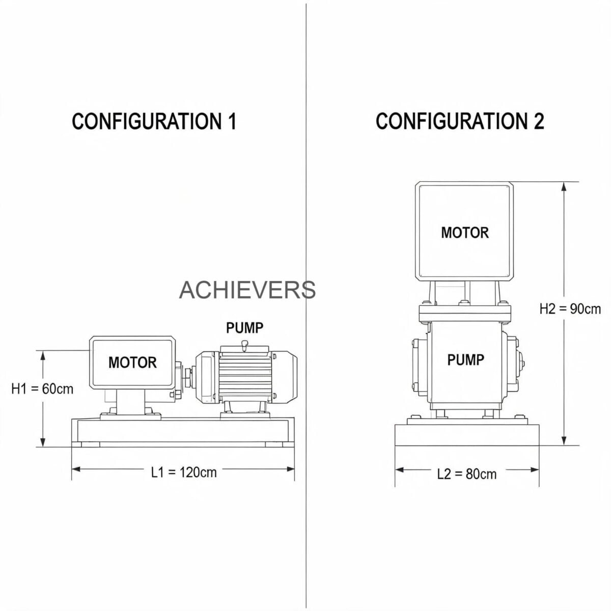
Engineering Note: Hydraulic Power and System Design
When sizing an electric rotary vane pump for a diesel fuel system, it is crucial to calculate the hydraulic power required to overcome both the static head and the dynamic friction losses in the piping network.
Hydraulic Power Calculation:
P = (Q * H * SG) / (6120 * Eff)
Where:
P is the required hydraulic power in kilowatts (kW).
Q is the flow rate in Liters per Minute (L/min).
H is the total dynamic head in meters (m).
SG is the specific gravity of the fluid (for diesel fuel, typically 0.83 to 0.85).
Eff is the volumetric and mechanical efficiency of the pump (typically 0.70 to 0.85 for new rotary vane pumps).
Electric models like the CE-80-DC rely on high current draw (up to 44A on a 12V system) to deliver 80 L/min. Because the electrical energy converts partially into heat, these pumps are strictly rated for a 30-minute duty cycle. Exceeding this cycle risks thermal breakdown of the motor windings and the acetal resin vanes. In contrast, pneumatic pumps expand compressed air, producing a cooling effect that allows for continuous, 24/7 operation without thermal degradation.
3. Application Comparison Table
Selecting the appropriate fluid transfer architecture requires matching the pump's mechanical characteristics to the exact fluid rheology and environmental constraints of the installation.
| Application Scenario | Recommended Option | Engineering Reason |
| :— | :— | :— |
| Hazardous Area (ATEX Zone 1/2) | Pneumatic (AODD) | Inherently safe by design. Zero electrical sparking risk. No expensive Ex-d enclosures required. |
| Remote Mobile Fuel Dispensers | Electric (12V/24V DC) | Easily powered by vehicle batteries. Compact footprint and low weight (e.g., 3.5 kg for CE-40DC). |
| High Precision Batching Control | Electric (Continuous flow) | Smooth, non-pulsating flow profile pairs perfectly with precision Positive Displacement Flow Meters. |
| High Viscosity Lubricants / Cold Weather | Pneumatic (AODD) | Can handle shear-sensitive and highly viscous cold fluids without motor stalling or overloading. |
| Intermittent / Dead-Heading Operations | Pneumatic (AODD) | Can safely stall under pressure when a downstream valve closes without needing a bypass loop. |
| Standard Diesel Tank Farms | Electric (High Flow AC/DC) | High efficiency for transferring clean, low-viscosity diesel efficiently at up to 120 Liters/Min. |
| Heavy Particulate / Dirty Oils | Pneumatic (AODD) | Diaphragm design passes solids up to several millimeters without jamming, unlike tight-tolerance vanes. |
| Automated Fuel Consumption Tracking | Electric | Constant motor speed ensures steady pressure delivery to downstream Fuel Flow Meters. |
4. Total Cost Comparison
Procurement teams must evaluate fluid transfer systems on a Total Cost of Ownership (TCO) basis rather than solely relying on the initial capital expenditure. Global plants, similar to those utilizing Fuel Transfer Pumps in India for industrial diesel transfer, require rigorous lifecycle cost modeling. While local pricing varies, the relative economic footprint of these technologies remains consistent globally.
| Option | Initial Capital Expenditure (Relative Cost) | Utility & Energy Costs | Annual Maintenance | Expected Lifecycle | Best For |
| :— | :— | :— | :— | :— | :— |
| Electric DC Vane Pump (e.g., CE-40DC) | Low Base Cost | Low (Direct electrical efficiency is high; runs off standard 12V/24V systems) | Moderate (Vane replacement, bypass valve cleaning, carbon brush wear) | 3 – 5 Years (Under strict 30-min duty cycle adherence) | Mobile bowsers, light industrial machinery refueling |
| Electric Heavy Duty (e.g., CE-80-DC) | Medium Base Cost | Low to Moderate (Requires robust alternators/batteries for 44A draw) | Moderate (Routine strainer checks, periodic motor servicing) | 4 – 7 Years | High-volume intermittent transfer, earth-moving machinery |
| Pneumatic Diaphragm Pump (AODD) | Medium to High Base Cost | High (Compressed air is an expensive utility, susceptible to system leaks) | Low (Only periodic diaphragm and ball valve replacement) | 7 – 10+ Years (Highly resilient to abuse and dry-running) | Hazardous environments, continuous heavy-duty industrial processing |
Air generation is universally one of the most expensive plant utilities. While a pneumatic pump may have lower maintenance costs due to fewer moving parts and its ability to run dry safely, the cost of running an air compressor continuously can dwarf the electrical costs of an equivalent rotary vane pump over a five-year period. Therefore, buyers looking to buy fuel transfer pumps for manufacturers should calculate their plant's compressed air cost per standard cubic foot per minute (SCFM) before defaulting to pneumatic solutions.
5. Decision Guide: Which One for Your Plant?
To ensure maximum operational efficiency and safety, follow this technical procedure when selecting your pump architecture. This methodology is utilized by instrumentation engineers globally to specify equipment capable of surviving demanding industrial environments.
- Classify the Hazardous Area Risk: Before assessing flow requirements, evaluate the installation environment. If the pump will be located in an ATEX Zone 0 or Zone 1 environment, or if you are transferring highly volatile fluids with low flash points (like gasoline), a pneumatic pump is the safest default. If transferring diesel or kerosene in safe, non-classified zones, electric models are generally preferred for their simplicity.
- Determine the Available Utilities: Check what power sources are reliably available. For mobile earth-moving machinery, construction yards, or agricultural fleets, a 12V or 24V DC battery supply is standard, making the CE-40DC, CE-70-A-DC, or CE-80-DC the logical choice. If the plant has a robust, clean compressed air ring main, pneumatic becomes viable.
- Calculate Required Flow Rate and Total Dynamic Head: Determine your throughput requirements. If you need to refuel heavy machinery quickly, an 80 L/min to 120 L/min electric pump reduces vehicle downtime. Use the hydraulic power formula to ensure the pump head (e.g., 10m on the CE-70-A-DC) can overcome vertical lifts and piping friction.
- Evaluate the Duty Cycle Requirements: This is where many plant managers make critical errors. Electric DC vane pumps are engineered with permanent magnet stators and are strictly rated for a 30-minute continuous duty cycle. If your process requires continuous transfer for hours (e.g., polishing tank farms), you must either install automated cool-down staging logic, opt for continuous-duty AC motors, or select a pneumatic pump that handles 100% duty cycles via air cooling.
- Assess Fluid Viscosity and Cleanliness: Rotary vane pumps excel with clean, lubricating fluids like diesel, kerosene, and light hydraulic oils. The built-in strainers protect the internal sintered steel rotors. However, if the fluid is highly viscous, cold, or contaminated with abrasive particulates (e.g., waste oil), a pneumatic diaphragm pump will prevent the internal jamming and mechanical shear that would destroy a vane pump.
- Analyze Downstream Instrumentation Requirements: If your system feeds into precision volumetric measurement instruments, electric pumps are superior. Rotary vane pumps provide a smooth, continuous flow profile. Pneumatic diaphragm pumps inherently pulse, which can cause severe measurement errors in turbine or vortex meters unless dampeners are installed.
- Design for Dead-Heading and Bypass: In dispensing operations where an operator might shut a manual nozzle abruptly, electric pumps rely on their built-in bypass valves to recirculate fluid internally and prevent line bursts. However, operating in bypass for more than 2-3 minutes generates extreme heat. Pneumatic pumps simply stop pumping and hold pressure against the closed valve indefinitely, offering foolproof mechanical safety.
- Finalize the Lifecycle Cost Analysis: Compare the capital cost of the pump against maintenance intervals. Electric pumps feature factory-lubricated bearings and lightweight die-cast aluminum or cast iron construction for long life, but the internal acetal resin vanes will eventually wear and require a simple rebuild kit. Factor these rebuild intervals into your standard operating procedures.
FAQ
Q: Can I run an electric 12V/24V DC rotary vane pump continuously for hours?
A: No. Standard DC electric vane pumps, such as the CE-40DC and CE-80-DC, are designed with a strict 30-minute duty cycle. Running them continuously will cause thermal overload, potentially degrading the permanent magnet stator and melting the internal acetal resin vanes. They must be allowed to cool down between operational batches.
Q: Will a pneumatic pump provide a steady enough flow for high-accuracy flow meters?
A: Out of the box, no. Pneumatic air-operated double diaphragm (AODD) pumps create a pulsating flow profile. To achieve high accuracy with downstream flow meters, you must install an active pulsation dampener in the discharge line, or alternatively, utilize an electric rotary vane pump that naturally provides a smooth, continuous fluid stream.
Q: What happens if a downstream dispensing nozzle is closed while the electric pump is running?
A: Industrial electric models feature a built-in bypass valve incorporated directly into the pump body. When the nozzle closes, the valve opens, allowing the fluid to recirculate internally. However, the pump should not be left in bypass mode for more than a few minutes, as the friction will rapidly heat the fuel and risk cavitation.
Q: Are electric rotary vane pumps safe for transferring highly flammable fluids like gasoline?
A: Standard IP55-rated electric pumps are designed for combustible fluids with higher flash points, such as diesel fuel, kerosene, and light fuel oils. Transferring highly volatile, flammable fluids like gasoline typically requires specialized explosion-proof (ATEX-certified) electric motors or intrinsically safe pneumatic transfer solutions.
Q: How does extreme cold weather impact the performance of these pumps?
A: In severe global site conditions, extreme cold increases the kinematic viscosity of diesel fuel and causes paraffin wax to precipitate out. This increased viscosity puts higher torque demands on electric pump motors and increases the amperage draw. Pneumatic pumps handle cold, viscous fluids better but require extremely dry compressed air to prevent the exhaust mufflers from freezing due to rapid air expansion.
Q: Do I need to manually prime the CE-70-A-DC and CE-80-DC pumps before the first use?
A: These pumps are engineered as positive displacement, self-priming vane pumps. They are capable of evacuating air from the suction line and lifting fluid (typically 2 to 4 meters of suction lift) without manual priming. However, ensuring the inlet line is free of major air leaks is critical for achieving the stated 10-meter delivery head.
Q: What maintenance is required for the electrical DC transfer pumps?
A: Maintenance is minimal but essential. The built-in strainer must be cleaned periodically to prevent cavitation. The internal acetal resin vanes wear down over time and should be replaced according to the manufacturer's operational hour guidelines. Additionally, the electrical connections and carbon brushes (if applicable) should be inspected for wear and secure contact.
For complex fluid handling architectures, selecting the correct instrumentation requires engineering oversight tailored to your specific operational constraints. If you require further technical assistance regarding flow capacities, duty cycle configurations, or material compatibility for extreme global site conditions, contact our engineering team to discuss your Fuel Transfer Pumps enquiry, application specifics, and throughput requirements today.