
Precision in fluid measurement is not merely a matter of operational tracking; it is the bedrock of mass balance, custody transfer, and process optimization in global industrial applications. Selecting the wrong instrumentation for transfer skids, generator day tanks, or bulk receipt lines leads to volumetric discrepancies, pump cavitation, and costly downtime. As industrial facilities scale operations—whether offshore platforms, chemical batching plants, or power generation facilities—the demand for robust, highly accurate flow measurement technologies becomes paramount.
This comprehensive buyer's guide provides a methodical selection checklist for matching flow meter performance to real-world operating conditions, specifically focusing on viscosity ranges, temperature extremes, line pressures, and required accuracy classes. By examining critical specifications, this guide equips instrumentation engineers, plant managers, and procurement heads with the technical framework required to evaluate and specify Turbine Flow Meters for complex fluid networks. Whether you are upgrading an existing pipeline or commissioning a new facility, understanding these parameters ensures compliance with international measurement standards and guarantees long-term reliability.
1. What Are [Turbine Flow Meters] and How Do They Operate
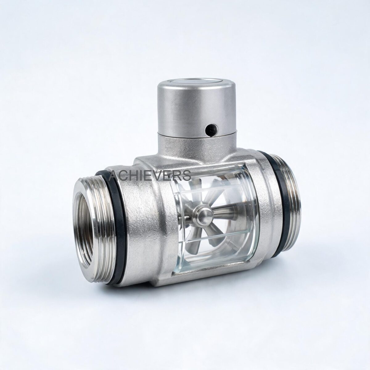
At their core, Turbine Flow Meters are velocity-based measurement devices designed for the highly accurate volumetric calculation of low-viscosity, non-acidic liquids such as diesel, water, heavy oil, and furnace oil. Their operation relies on the conservation of angular momentum and the dynamic forces of the flowing fluid.
The measurement process begins as the flowing liquid enters the meter body and passes through a straightening section. These integrated straightening vanes condition the liquid flow profile by neutralizing undesired swirl, turbulence, and asymmetry before the fluid reaches the measurement rotor. Once conditioned, the liquid impacts a freely suspended turbine wheel featuring helical blades set at a precise, known angle relative to the fluid flow. The kinetic energy of the fluid drives the turbine wheel, causing it to rotate at an angular velocity that is strictly proportional to the linear fluid velocity.
The rotor is mounted on a hard stainless steel main shaft supported by special high-precision, low-friction ball bearings and a carbon bush, minimizing mechanical drag. As the turbine wheel spins, a proximity probe (magnetic pickoff sensor) detects the passing of each rotor blade, generating a pulsed electrical signal. Each pulse represents a discrete, known volume of liquid. By applying a device-specific K-factor (pulses per unit volume), the electronic display or data acquisition module calculates total passed volume and instantaneous flow rate. Alternatively, mechanical index heads driven via shafts and gears can indicate these values on an eight-digit counter.
Below are the defining technical specifications for industrial turbine flow meters for non-acidic liquids:
| Technical Specification | Value / Rating | Engineering Notes |
| Measuring Principle | Volumetric Velocity | Proportional angular velocity via helical rotor |
| Material of Construction | Enclosure & Rotor: S.S-304 / S.S-316 | Corrosion-resistant; suitable for harsh environments |
| Shaft Assembly | Hard Stainless Steel-316 with Carbon Bush | Low friction, extended operational lifespan |
| Standard Accuracy | +/- 0.5% or 1% FSD | Requires fully developed flow profile |
| Repeatability | 0.1% | Excellent for batching and process control |
| Maximum Working Pressure | 6 MPa (approx. 60 Bar) | Suitable for high-pressure transfer lines |
| Temperature Range | -20 to 120 °C | Ambient and fluid temperature tolerance |
| Pulse Output Signal | NPN Open Connector (12V DC power) | High Level: >8 VDC / Low Level: <0.8 VDC |
2. Key Selection Criteria for Global Industrial Buyers
Specifying a flow meter requires evaluating the fluid's physical properties against the mechanical and electronic capabilities of the instrument. When evaluating turbine flow meter specifications for industrial buyers, instrumentation engineers must weigh several critical parameters against alternative technologies.
Technology Comparison Table
To understand where turbine technology fits into your plant architecture, compare it against other dominant flow measurement principles such as Electromagnetic Flow Meters and Positive Displacement Flow Meters.
| Parameter | Turbine Flow Meter | Electromagnetic Meter | Vortex Flow Meter | Positive Displacement |
| Primary Fluid Target | Clean liquids (Fuel, Oil, Water) | Conductive liquids (Water, Slurry) | Liquids, Gases, Steam | Highly viscous fluids (Syrups, Heavy Oils) |
| Viscosity Tolerance | Low to Medium | Irrelevant | Low | High to Very High |
| Pressure Drop (Head Loss) | Moderate (varies by flow rate) | Zero (unobstructed pipe) | Moderate (bluff body) | High (mechanical clearances) |
| Accuracy Capability | High (+/- 0.5% to 1%) | High (+/- 0.5% to 1%) | Moderate (+/- 1% to 1.5%) | Very High (+/- 0.1% to 0.5%) |
| Straight Pipe Requirement | 10D Upstream / 5D Downstream | 5D Upstream / 3D Downstream | 15D Upstream / 5D Downstream | None required |
| Maintenance Need | Bearings require periodic check | Minimal (no moving parts) | Minimal (no moving parts) | High (wear on gears/vanes) |
Criterion 1: Fluid Viscosity and Reynolds Number Limits
Turbine meters operate optimally within specific kinematic viscosity ranges. If the fluid viscosity exceeds design limits, the drag on the rotor blades increases, shifting the calibration curve and degrading accuracy. Since turbine meters are dependent on a fully developed turbulent flow profile (typically a Reynolds number greater than 10,000), using them for highly viscous heavy oils below the critical flow threshold requires careful K-factor characterization.
Criterion 2: Pressure Drop and System Cavitation
All mechanical flow meters introduce pressure drop (head loss). At high flow velocities, the pressure immediately downstream of the turbine rotor drops. If this pressure falls below the vapor pressure of the liquid, cavitation occurs—vapor bubbles form and subsequently collapse. Cavitation not only causes severe mechanical damage to the stainless steel rotor blades and carbon bush but also causes the meter to over-register. Engineers must ensure sufficient downstream backpressure, typically calculated as: Backpressure = 2 x (Pressure Drop) + 1.25 x (Vapor Pressure).
Criterion 3: Material Compatibility and Operational Extremes
Global operating conditions—whether in corrosive coastal facilities or extreme temperature zones—dictate strict material choices. A standard build using an S.S-304 or S.S-316 enclosure and rotor provides broad chemical resistance against fuels, water, and non-acidic process fluids. The pressure rating of 6 MPa (60 bar) and temperature tolerance from -20 to 120 °C covers the vast majority of boiler feed lines, generator fuel lines, and loading arm applications.
Criterion 4: Transmitter, Display, and Communications
Modern industrial networks require seamless data integration into DCS or SCADA systems. Buyers must specify the correct power and output architecture:
- Pulse Output: A 12V DC powered NPN open connector is ideal for high-speed batching controllers.
- Analog Output: 24V DC powered 4 to 20 mA signals are standard for long-distance DCS analog inputs.
- Digital Communication: Many buyers opt to buy turbine flow meters with RS485 output, utilizing Measurement Systems Pickoff Sensor modules for robust, multi-drop digital integration across vast plant networks.
- Standalone Power: For remote wellheads or unpowered transfer skids, a battery-operated meter featuring a 3.3V 10AH lithium battery provides over 5 years of continuous operation, complete with an LCD displaying instantaneous flow and an eight-digit cumulative total with power-fail protection.
3. Model and Variant Comparison
Sizing the meter correctly is the single most important step in the procurement process. An oversized meter will run in its non-linear low-end range, while an undersized meter will create excessive pressure drop, wear out the bearings prematurely, or induce cavitation. Match your expected nominal flow rate to the mid-point of the meter's specified range.
Below is the technical data for the CE-TFS series line sizes and corresponding flow ranges:
| Model Number | Line Size | Flow Range (Liters / Hour) | Application Suitability |
| CE-TFS-004 | 04 MM | 40 ~ 400 L/H | Micro-dosing, pilot plant testing, small burner feeds |
| CE-TFS-012 | 12 MM | 600 ~ 6,000 L/H | Standard generator day tanks, light transfer pumps |
| CE-TFS-025 | 25 MM | 1,000 ~ 10,000 L/H | Commercial fuel dispensers, process batching |
| CE-TFS-040 | 40 MM | 2,000 ~ 20,000 L/H | Mid-scale chemical transfer, water treatment lines |
| CE-TFS-050 | 50 MM | 4,000 ~ 40,000 L/H | Bulk fuel loading, medium industrial process lines |
| CE-TFS-080 | 80 MM | 10,000 ~ 100,000 L/H | High-volume transfer skids, offloading stations |
| CE-TFS-100 | 100 MM | 20,000 ~ 200,000 L/H | Main plant intake lines, large boiler feeds |
| CE-TFS-150 | 150 MM | 30,000 ~ 300,000 L/H | Heavy industrial bulk transfer, pipeline monitoring |
| CE-TFS-150 (High Cap) | 150 MM | 80,000 ~ 800,000 L/H | Major terminal operations, large-scale custody transfer |
4. Common Mistakes Industrial Buyers Make When Choosing
Even top-tier instrumentation will fail if poorly selected or incorrectly installed. Global procurement teams consistently run into a few structural pitfalls when deploying volumetric measurement systems. Avoid these five critical mistakes:
- Skipping Upstream Filtration
Turbine meters contain precision bearings and tight clearances between the rotor blades and the housing. Allowing particulate matter, pipe scale, or weld slag into the meter will jam the rotor or destroy the bearings. Always install an appropriate Y-strainer or basket filter upstream of the meter body.
- Ignoring Straight Pipe Run Requirements
Turbine meters rely on a symmetrical, fully developed flow profile. Installing a meter immediately after a pump, a 90-degree elbow, or a control valve introduces swirl and fluid jetting. This distorts the velocity profile striking the helical blades, causing massive accuracy errors. Always provide a minimum of 10 pipe diameters (10D) of straight, unobstructed pipe upstream and 5 pipe diameters (5D) downstream.
- Sizing Based Only on Pipe Diameter
Procurement often makes the mistake of matching the flow meter size directly to the existing pipe size without checking actual fluid velocities. If a 100 MM pipe is only carrying 5,000 L/H, a CE-TFS-100 meter will barely turn, leading to massive under-registration. Always size the meter based on the actual Min/Max Flow Rate, even if it means using pipe reducers.
- Failing to Account for Extreme Viscosity Shifts
When learning how to choose turbine flow meters for diesel fuel transfer, buyers must account for seasonal temperature changes. Diesel fuel thickens significantly at -10 °C compared to 30 °C. As viscosity increases, the meter's K-factor shifts. If temperature fluctuations are extreme, multi-point calibration curves or a transition to Positive Displacement meters may be required.
- Inadequate Electrical Grounding in Hazardous Areas
Industrial facilities processing fuels are classified hazardous environments (ATEX, IECEx, or Class I Div 1). Using standard pulse outputs without proper intrinsically safe barriers, galvanic isolators, or shielded cables leads to noisy signals, phantom pulse counting, and severe safety risks. Always match the sensor housing and wiring standards to the site's classification.
5. Enquiry Specification Checklist
To streamline procurement and eliminate engineering ambiguity—especially when dealing with international vendors or evaluating a turbine flow meters supplier in India for export to global facilities—use this methodical checklist when requesting a quotation.
When to Use This Technology: A Decision Matrix
| Operating Scenario | Recommended Technology | Reasoning |
| Clean Diesel / Water / Light Oil, steady flow, tight budget | Turbine Flow Meter | High accuracy at lower capital cost, excellent repeatability. |
| Extremely viscous crude oil, fluctuating pressures | Positive Displacement | Immune to viscosity shifts, no straight pipe requirement. |
| Raw wastewater with high particulate, conductive | Electromagnetic | Zero obstruction, no moving parts to jam, handles solids. |
| High-temperature steam or mixed gas | Vortex Flow Meter | Operates across extreme temperatures, no moving parts. |
Engineering Calibration Note: The K-Factor
Every turbine meter is delivered with a calibration certificate detailing its unique K-factor (Pulses per Liter or Pulses per Gallon). The fundamental equation governing the instrumentation is:
Flow Rate = (Pulse Frequency * 60) / K-factor
Where Flow Rate is in Liters per Minute, Frequency is in Hertz (pulses per second), and the K-factor is Pulses per Liter. During installation, this exact K-factor must be entered into the local LCD, the PLC, or the batch controller. Failure to program the precise K-factor results in permanent systemic error.
8-Step Specification Checklist
- Fluid Properties: Specify the exact fluid type, density, and expected kinematic viscosity range (in centistokes or cSt) under operating conditions. Note if the liquid is non-acidic.
- Operating Flow Range: Define the absolute minimum, normal, and maximum expected flow rates (e.g., L/H or m3/h). Ensure the nominal flow falls at roughly 60% of the meter's maximum capacity.
- Line Size and Connections: Specify the nominal pipe size and the required mechanical connection (e.g., Flange ANSI 150#, PN16, or Threaded M/F).
- Temperature Profile: State the ambient environment temperature and the fluid operating temperature (must fall within the -20 to 120 °C rating).
- Pressure Rating: Document the normal operating pressure and maximum system design pressure (up to 6 MPa).
- Required Accuracy Class: Specify the maximum allowable error (+/- 0.5% or +/- 1% FSD) and required repeatability (standard is 0.1%).
- Materials of Construction: Confirm S.S-304 or S.S-316 requirements for both the body enclosure and the internal rotor mechanism.
- Output and Power Requirements: Clearly state if the site requires a standalone 3.3V battery-operated LCD, a 12V DC NPN pulse output for a controller, a 24V DC 4-20mA analog signal for DCS, or RS485 communication protocols for plant-wide data acquisition.
FAQ
Q: Can turbine flow meters measure highly acidic or corrosive chemicals?
A: No. While the S.S-304/S.S-316 stainless steel body and rotor provide excellent durability for fuels, water, and non-acidic liquids, highly corrosive acids will degrade the carbon bush and rotor blades. For harsh acids, specialized lined electromagnetic meters or ultrasonic meters are required.
Q: Do I need a straight pipe run if I install a flow straightener?
A: Yes. Even though high-quality turbine meters feature internal straightening vanes to condition the fluid profile, they still mandate a minimum external straight pipe run. Industry standard dictates 10 pipe diameters upstream and 5 pipe diameters downstream to guarantee the +/- 0.5% or 1% FSD accuracy.
Q: What happens if air or gas bubbles enter the turbine meter?
A: Air entrapment causes the fluid velocity to spike artificially, spinning the rotor much faster than the actual liquid volume warrants. This leads to massive over-measurement (often registering 20-30% more volume). Always install an air eliminator upstream if the line is susceptible to two-phase flow or air pockets.
Q: How often do the internal bearings and carbon bush need replacement?
A: Maintenance intervals depend strictly on fluid lubricity and operating hours. For lubricating fluids like diesel or hydraulic oil, bearings can last several years without degradation. For non-lubricating fluids like demineralized water, instrumentation teams should inspect and potentially recalibrate the rotor assembly annually.
Q: What is the benefit of buying a meter with RS485 output?
A: RS485 is a robust, multi-drop serial communication standard that resists electrical noise across long cable runs. It allows a single plant network to collect precise digital flow data, totalized volumes, and diagnostic alerts from dozens of meters using a single integrated loop, bypassing the calibration drift associated with analog 4-20mA signals.
Q: What does the power-fail protection on the battery-operated model do?
A: The battery-operated meter utilizes a dual-row LCD powered by a 3.3V 10AH lithium battery. The power-fail protection features non-volatile memory that safely stores the instrument coefficient (K-factor) and the accumulated total flow values for up to ten years, ensuring no critical mass-balance data is lost during battery swaps or power drops.
Q: Can these meters handle bidirectional flow?
A: Standard industrial turbine meters are calibrated and optimized for unidirectional flow, as indicated by the flow direction arrow on the meter body. Reversing the flow will strike the trailing edge of the helical blades, yielding highly inaccurate pulse data and potentially unseating the bearing assembly over time.
To discuss your specific fluid application, viscosity constraints, or to verify sizing configurations for your facility, contact our technical instrumentation team today. Please provide your nominal flow rate, fluid type, operating temperature, and required communication output, and we will engineer a precise volumetric measurement solution tailored to your site's operational demands.