
In global fuel oil transfer terminals, the stakes for fluid measurement are astronomically high. When transferring marine diesel, furnace oil, or heavy fuel oils at rates up to 800,000 liters per hour, a measurement error of just a fraction of a percent translates into millions of dollars in unaccounted losses annually. Terminal operators, plant managers, and instrumentation engineers require measurement technologies that offer high-speed response, exceptional repeatability, and unyielding reliability under harsh industrial conditions.
While many technologies exist for liquid measurement, Turbine Flow Meters remain a gold standard for clean, low-to-medium viscosity hydrocarbons. Their operational mechanics—translating the kinetic energy of a flowing fluid directly into rotational velocity—provide highly linear pulse outputs ideal for custody transfer, rail/truck loading skids, and continuous in-line blending operations.
This comprehensive engineering guide explores the application of Turbine Flow Meters in high-capacity fuel oil environments. We will analyze their mechanical design, compare them against alternative measurement technologies, and provide actionable integration strategies for global industrial facilities demanding strict API and ISO compliance.
1. Industry Overview: The Fluid Challenge
High-volume fuel terminals operate in punishing environments. From the sub-zero temperatures of North American winters to the extreme ambient heat of Middle Eastern petrochemical facilities, flow measurement instrumentation must perform flawlessly. The fluids handled—ranging from refined diesel to heavy furnace oils—present specific hydrodynamic challenges.
A primary challenge in fuel terminal operations is maintaining a stable flow profile. Loading pumps generate hydraulic pulsations and swirl, disrupting the velocity profile of the liquid. Furthermore, heavy fuel oils exhibit fluctuating kinematic viscosities depending on temperature variations. For custody transfer, international legal metrology standards demand measurement repeatability of 0.1% or better.
Generic flow meters often fail in these environments due to excessive pressure drops, mechanical degradation, or signal drift caused by varying fluid temperatures. Achieving the required precision requires an instrument engineered with flow conditioning capabilities and robust materials capable of withstanding maximum working pressures up to 6 MPa (60 bar) and fluid temperatures ranging from -20 to 120 °C.
2. Product Capabilities Matched to Industry Needs
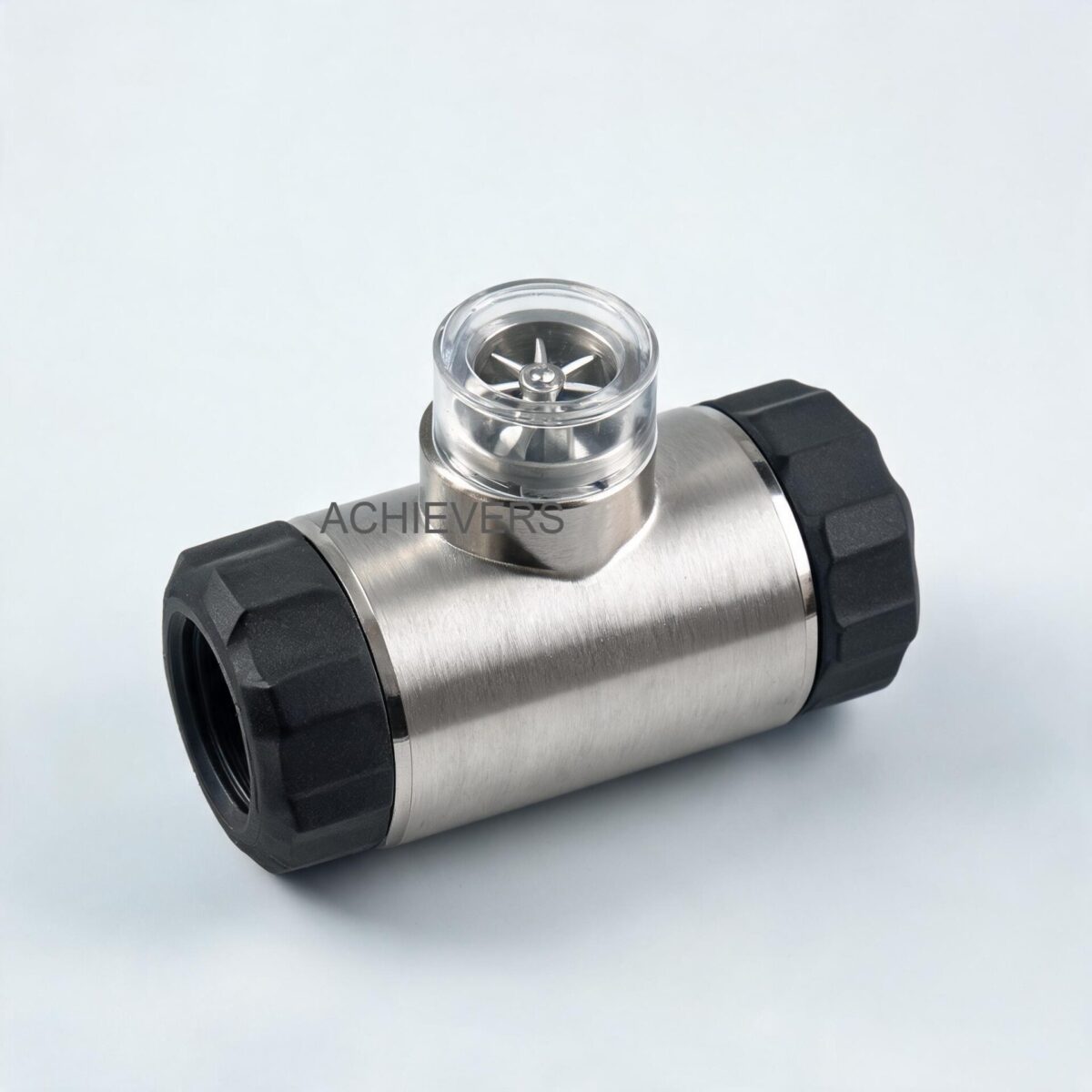
The mechanical architecture of Turbine Flow Meters is specifically designed to counteract the fluid dynamics challenges present in terminal operations. The operation is based on the measurement of the fluid's velocity. As the liquid enters the meter body, it is accelerated and conditioned by an integrated straightening section. These straightening vanes prepare the flow profile by actively removing undesired swirl, turbulence, and asymmetry before the fluid strikes the turbine wheel.
The dynamic force of the flowing fluid causes the helical-bladed rotor to spin on a main shaft supported by high-precision, low-friction ball bearings. Because the blades are set at a known angle relative to the fluid flow, the angular velocity of the rotor is directly proportional to the fluid velocity.
Technical Specifications Matrix
Below is a detailed breakdown of the technical capabilities and model specifications designed for industrial fuel oil applications:
| Specification Parameter | Technical Data / Material | Engineering Significance |
| :— | :— | :— |
| Enclosure Material | S.S-304 / S.S-316 | Exceptional corrosion resistance against harsh industrial environments and acidic trace elements in heavy oils. |
| Rotor Material | S.S-304 / S.S-316 | Withstands high kinetic impact at maximum flow rates without blade deformation. |
| Shaft & Bearings | Hard Stainless Steel-316 with carbon bush | Ensures low-friction rotation, yielding exceptional 0.1% repeatability and extending operational lifespan. |
| Accuracy Rating | +/- 0.5% or 1% FSD | Meets stringent requirements for process control, batching, and general transfer measurement. |
| Repeatability | 0.1% | Crucial for custody transfer and proportional in-line blending operations. |
| Max Working Pressure | 6 MPa (approx. 60 bar) | Capable of handling high-head loading pumps without mechanical housing failure. |
| Temperature Range | -20 to 120 °C | Accommodates heated heavy fuel oils and extreme global ambient conditions. |
High-Capacity Model Variants
To accommodate everything from pilot plant dosing to massive ship-to-shore bunkering, these meters are scaled across a wide range of line sizes:
| Model No | Line Size | Flow Range (L/H) | Application Focus |
| :— | :— | :— | :— |
| CE-TFS-004 | 4 mm | 40 ~ 400 L/H | Additive injection / pilot lines |
| CE-TFS-025 | 25 mm | 1,000 ~ 10,000 L/H | Light commercial transfer / dispensing |
| CE-TFS-050 | 50 mm | 4,000 ~ 40,000 L/H | Truck loading skids / medium transfer |
| CE-TFS-100 | 100 mm | 20,000 ~ 200,000 L/H | Railcar loading / heavy transfer |
| CE-TFS-150 | 150 mm | 30,000 ~ 300,000 L/H | Mainline pipeline transfer |
| CE-TFS-150 (High) | 150 mm | 80,000 ~ 800,000 L/H | High-volume custody transfer / ship loading |
Engineering Principle: The K-Factor and Fluid Dynamics
The translation of mechanical rotation to electronic data is achieved via a proximity probe. As each ferromagnetic turbine blade passes the probe, it interrupts the magnetic field, generating an electrical pulse.
The relationship between the volume of fluid passing through the meter and the number of pulses generated is defined by the meter's K-factor.
Flow Rate Calculation:
Flow Rate (Q) = Frequency (f) / K-factor
Where:
- Q = Volumetric flow rate (e.g., Liters per second)
- f = Output frequency in Hertz (Pulses per second)
- K-factor = Calibration constant (Pulses per Liter)
Engineering Note on Viscosity: Because turbine meters rely on the Reynolds number of the fluid remaining in the turbulent flow regime, significant shifts in kinematic viscosity (common when temperatures drop in heavy fuel oils) can alter the velocity profile and shift the K-factor. For optimal accuracy in viscous fluids, calibration must be performed at the fluid's operating temperature and viscosity.
3. Technology Comparison: Selecting the Right Meter for Fuel Terminals
No single flow measurement technology is perfect for every application. Instrumentation engineers must weigh accuracy against pressure drop, maintenance requirements, and fluid properties. Here is how turbine technology compares to other common measurement principles in the fuel oil sector.
Flow Measurement Technology Comparison Table
| Parameter | Turbine Flow Meter | Positive Displacement (PD) | Coriolis Mass Flow | Vortex Flow Meter |
| :— | :— | :— | :— | :— |
| Primary Output | Volumetric | Volumetric | Mass & Density | Volumetric |
| Best Fluid Types | Clean, low-medium viscosity (diesel, light oil) | High viscosity (crude, heavy bunker C) | All liquids and gases | Steam, gases, low-viscosity liquids |
| Accuracy (Typical) | 0.5% to 1.0% | 0.1% to 0.5% | 0.1% to 0.2% | 0.75% to 1.0% |
| Pressure Drop | Moderate to High | High | High | Medium |
| Viscosity Limit | Highly sensitive to changes | Immune/Improves with viscosity | Immune | Sensitive at high viscosities |
| Moving Parts | Yes (Rotor/Bearings) | Yes (Gears/Vanes) | No (Vibrating tubes) | No (Bluff body) |
| Purchase Cost | Low to Medium | High | Very High | Medium |
Decision Matrix: When to Use Turbine Technology
Choose Turbine Meters when:
- You are measuring refined fuels, marine diesel, or heated heavy fuel oils with relatively stable viscosities.
- You require a highly linear pulse output (NPN open connector) for direct integration into high-speed Liquid Batching Systems.
- You need a compact installation footprint compared to massive PD meters of the same line size.
- Your operation demands cost-effective scaling for massive flow rates (up to 800,000 L/H).
Consider alternatives when:
- You are measuring ultra-high viscosity crude oils at ambient temperatures (use Positive Displacement Flow Meters).
- You need to measure saturated or superheated steam in the plant utility sector (use Vortex Flow Meters).
- You must measure fluid mass directly rather than volume.
4. Typical Installation Scenarios in Fuel Terminals
Scenario A: Truck and Rail Loading Skids
For loading bays, speed and batch accuracy are critical. A 50mm or 80mm turbine meter is typically installed downstream of a loading pump and control valve. The meter utilizes a 12V DC power supply and outputs an NPN open connector high-frequency pulse signal (High level > 8 VDC, Low level < 0.8 VDC). This signal is fed directly into a batch controller, which counts the pulses in real time and commands the control valve to shut precisely as the target volume is reached, preventing expensive overfills.
Scenario B: Tank-to-Tank Transfer and Inventory Management
When transferring fuel oil between bulk storage tanks, line sizes increase (typically 100mm to 150mm). For remote tank farms lacking robust power infrastructure, the Battery Operated Meter variant is ideal. Operating on 3.3V 10AH lithium batteries capable of lasting over 5 years, these units feature a double-row Liquid Crystal Display (LCD). The display provides both instantaneous flow (m3/h or L/h) and an 8-digit cumulative totalizer. Crucially, they include power-fail protection, ensuring that the instrument coefficient and 10-year total flow values are never lost during maintenance.
Scenario C: Proportional In-Line Blending
Modern terminals often blend heavy furnace oil with lighter diesel to meet specific marine fuel viscosity grades. This requires instantaneous rate feedback to variable frequency drives (VFDs) controlling the blending pumps. In this scenario, the Display with 4 to 20 mA Output (powered by 24V DC) is utilized. The analog signal continuously broadcasts the real-time flow rate to the plant PLC or DCS, allowing PID loops to adjust pump speeds dynamically and maintain the exact blend ratio.
5. Compliance, Accuracy, and Certification Requirements
Global fuel terminals operate under strict regulatory scrutiny. Measurement systems used for financial transactions (custody transfer) must comply with international legal metrology guidelines, such as OIML R117, and industry practices outlined in API MPMS (Manual of Petroleum Measurement Standards) Chapter 5.3.
- API MPMS Chapter 5.3 Compliance: This standard dictates that turbine meters used for liquid hydrocarbons must maintain strict linearity and a repeatability of at least 0.05% to 0.1% over the specified flow range. The 0.1% repeatability rating of these meters, combined with proper flow conditioning (straightening vanes), meets these rigorous demands.
- Safety and Hazardous Areas: Fuel oil vapor environments require specialized electrical handling. The availability of 12V and 24V DC instrumentation, alongside RS485 communication, allows the meters to be integrated with intrinsically safe barriers or housed within ATEX/IECEx certified explosion-proof enclosures for global deployment in Zone 1 and Zone 2 hazardous areas.
- Material Certification: The S.S-304/316 construction ensures compliance with NACE MR0175 / ISO 15156 for materials utilized in potentially corrosive hydrocarbon environments.
6. ROI and Operational Benefits
Investing in high-precision measurement architecture yields immediate financial and operational returns for terminal operators.
| Operational Benefit | Typical Improvement Matrix | Terminal Industry Context |
| :— | :— | :— |
| Loss Prevention | Reduction of unaccounted liquid by up to 0.5% | In an 800,000 L/H transfer over 10 hours, a 0.5% error equals 40,000 liters. Accurate K-factor calibration eliminates this financial leakage. |
| Batching Precision | Valve shut-off accuracy improved to within liters | High-frequency pulse outputs allow high-speed batch controllers to close valves dynamically, preventing truck/railcar overfills. |
| Uptime & Maintenance | 5+ year continuous operation in remote zones | The 3.3V 10AH battery-operated LCD variant eliminates the need for expensive trenching and cabling in remote tank farm locations. |
| Data Integration | Real-time SCADA visibility | RS485 communication allows central control rooms to monitor transfer rates, totals, and diagnostic alarms globally. |

7. Engineering Procedure: Installation for Stable Flow Profiles
Because turbine meters measure velocity, they are highly sensitive to the fluid's velocity profile. Swirl or jetting caused by upstream elbows, valves, or pumps will cause the rotor to spin faster or slower than the true volumetric rate, destroying measurement accuracy.
Follow this rigorous 6-step engineering procedure for field installation to guarantee performance:
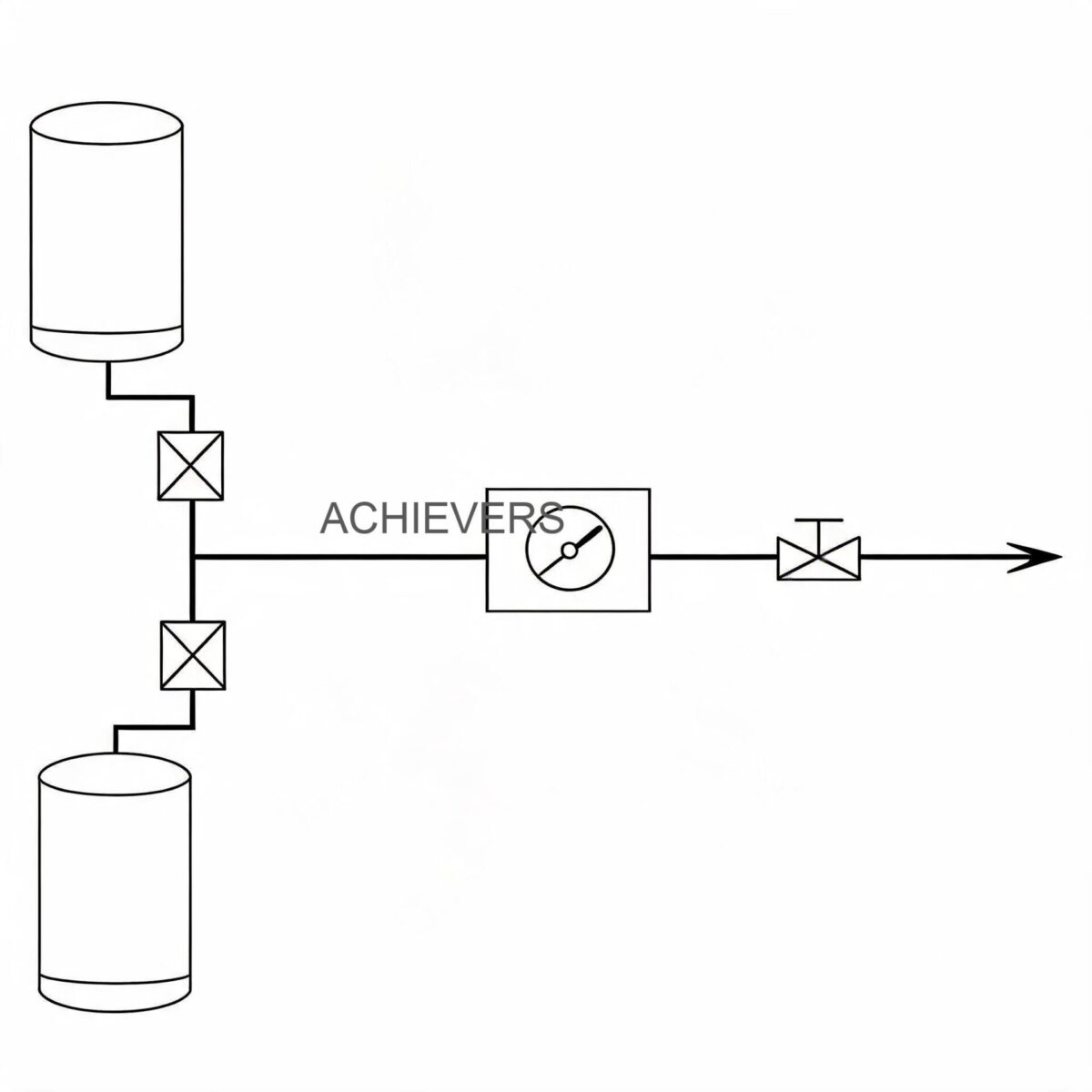
- Piping Geometry Configuration: Install the meter with strict adherence to straight pipe run requirements. Provide a minimum of 10 pipe diameters (10D) of straight, unobstructed pipe upstream of the meter, and 5 pipe diameters (5D) downstream.
- Strainer/Filter Integration: Turbine meters contain precision moving parts. Install a basket strainer upstream (prior to the straight pipe run) to catch pipeline scale, welding slag, or particulate matter. For diesel, a 100-mesh screen is recommended; for heavy fuel oils, use a coarser mesh paired with routine blowdowns.
- Air Elimination: Gas pockets or entrained air will cause "over-speeding" of the turbine rotor, leading to falsely high volume readings and potential bearing damage. Install an air eliminator or de-aeration vessel upstream of the measuring skid.
- Flow Conditioning Check: Ensure the internal straightening vanes are perfectly aligned with the pipe axis. When bolting flanged connections, verify that gaskets are perfectly centered and do not protrude into the flow stream, which would induce localized turbulence.
- Signal Shielding and Wiring: For the pulse output sensor (NPN open connector) or 4-20mA models, use high-quality twisted-pair shielded cabling. Ground the shield at one end only (typically at the control panel) to prevent ground loops and electromagnetic interference (EMI) from heavy loading pumps.
- In-Situ Proving and K-Factor Adjustment: Once installed, perform a baseline calibration run using a mechanical pipe prover, compact prover, or master meter. Calculate the field K-factor based on the actual operating temperature and viscosity of the fuel oil, and program this into the local display or batch controller.
FAQ
Q: Can this meter be used for both highly refined diesel and heavy furnace oil?
A: Yes, but with a critical caveat. Because the turbine's K-factor shifts with significant changes in kinematic viscosity, the meter must be re-proved (calibrated) if you switch from low-viscosity diesel to high-viscosity furnace oil. If your plant handles drastically different viscosities in the same line without recalibration, you should consider a positive displacement meter instead.
Q: What happens to the totalizer data if power is lost at the terminal?
A: The battery-operated dual-row LCD models and the externally powered models feature robust power-fail protection. The instrument coefficient and the cumulative flow values are stored in non-volatile memory and will remain intact for up to ten years without power.
Q: How long do the internal batteries last on the remote display units?
A: The battery-operated units utilize high-capacity 3.3V 10AH lithium batteries. Due to the ultra-low power consumption of the LCD and proximity circuitry, they are rated to operate continuously for more than 5 years without replacement.
Q: What is the maximum operating pressure the meter body can withstand?
A: The standard enclosure and internal components are engineered to withstand a maximum working pressure of 6 MPa (approximately 60 bar or 870 psi), making them suitable for high-head loading pumps and mainline transfer applications.
Q: Is it necessary to install a strainer upstream?
A: Absolutely. The turbine rotor spins on high-precision stainless steel shafts with carbon bushes. Any foreign debris, pipe scale, or rust will damage the delicate blade geometry or seize the bearings. Upstream filtration is non-negotiable for longevity.
Q: How does the meter output interface with a plant PLC?
A: The meter offers versatile outputs. For high-speed volumetric counting, it uses a 12V DC powered NPN open connector pulse output. For rate control, a 24V DC powered 4 to 20 mA analog output is available. Additionally, RS485 communication is supported for serial data acquisition via SCADA systems.
Q: What is the allowable fluid temperature range?
A: The meter is rated for fluid and ambient temperatures ranging from -20 °C to 120 °C, accommodating both cold climate operations and heavily heated fuel oils required to maintain pumpable viscosities.
To discuss the specific requirements of your fuel transfer terminal or loading skid, contact our engineering team with your required flow rate (L/H), line size, maximum operating pressure, and exact fluid viscosity. We will provide detailed K-factor sizing, pressure drop calculations, and output configuration options tailored to your custody transfer or batching applications.