
The management of bulk fuel storage and transfer is a critical operational pillar for global industries spanning mining operations, chemical processing, logistics fleets, and power generation. At the heart of this infrastructure are Diesel Dispensers, which serve a dual purpose: safe, high-volume fluid transfer and precise volumetric measurement. An unplanned failure of these dispensing systems halts fleet operations, while undetected meter drift results in compounding financial losses through fuel shrinkage and inaccurate inventory accounting.
Implementing a rigorous preventive maintenance program shifts fuel management from a reactive, break-fix paradigm to a predictable, cost-controlled operation. Industrial refueling environments—characterized by high particulate dust, extreme ambient temperatures, and variable fuel quality—accelerate the wear of mechanical pump components and electronic flow sensors. This technical guide establishes a comprehensive maintenance schedule and diagnostic framework designed to sustain metering accuracy, control contamination, and maximize the operational lifespan of industrial diesel dispensing equipment.
1. Product Overview and Critical Wear Components
Modern dispensing systems, such as the Achievers range by Lumen Instruments, integrate multiple electromechanical systems. Whether utilizing 220V AC powered units for permanent depot installations or 12V/24V DC powered mobile dispensers for remote site refueling, the core architecture remains consistent.
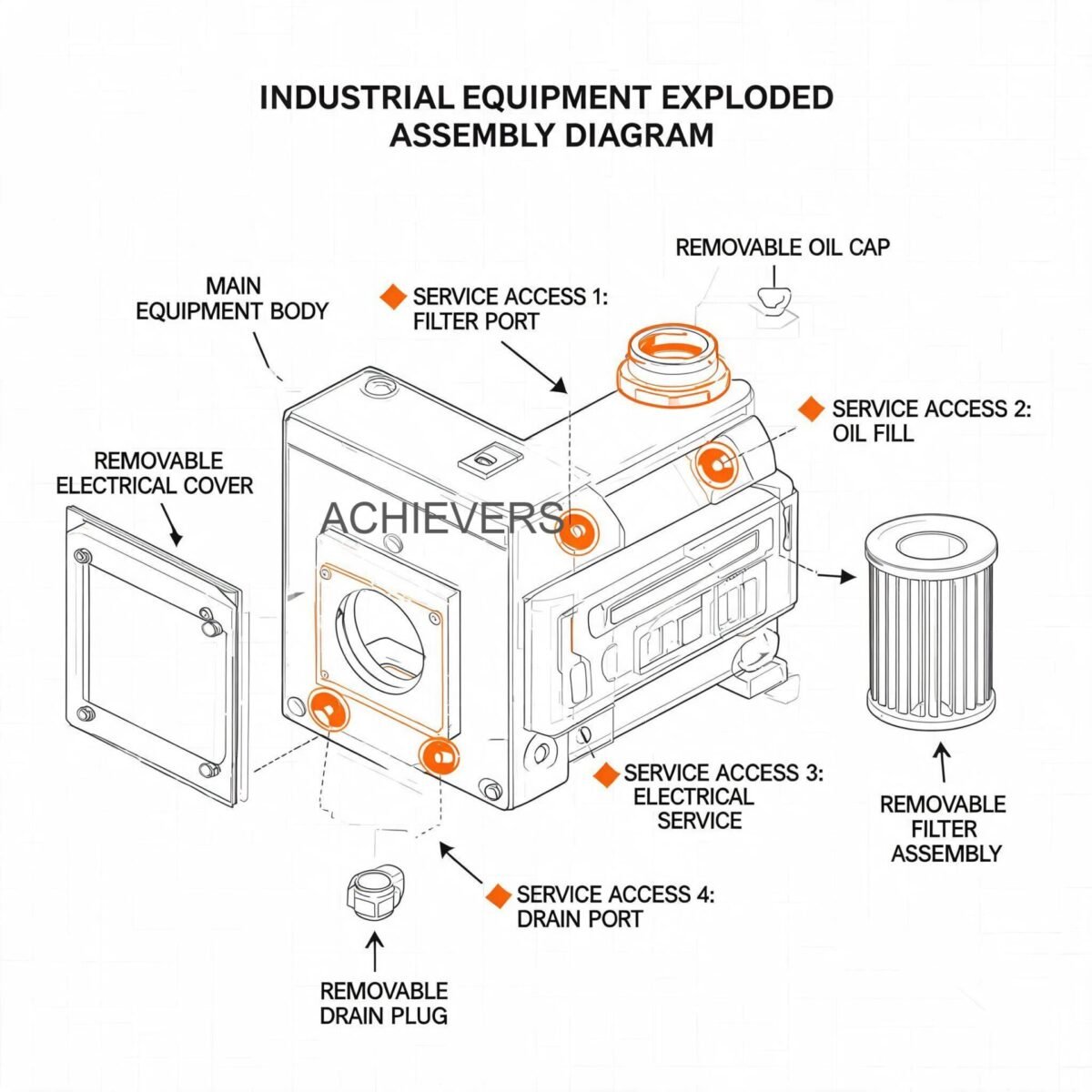
A standard industrial dispensing unit comprises a self-priming rotary vane or gear pump, an internal bypass valve, primary filtration, a volumetric flow meter (mechanical or electronic), a control board, and a dispensing nozzle with an automatic shut-off mechanism. Understanding the wear characteristics of these subsystems is fundamental to effective maintenance.
- Pumping Unit: The rotary vanes are consumable components. As they wear against the stator wall, pump efficiency decreases, potentially leading to cavitation if inlet restrictions (like clogged filters) occur.
- Flow Measurement Internal Mechanics: Positive displacement (PD) meters, commonly used in Diesel Dispensers, rely on tight mechanical clearances between internal rotors and the measuring chamber walls. Particulate ingress scores these surfaces, allowing fluid slip and causing under-registration of dispensed volumes.
- Filtration Housing: Strainers and particulate filters protect the meter and pump. Neglecting filter maintenance increases differential pressure, stressing pump seals and motor windings.
- Dispensing Nozzle: The venturi tube within the automatic shut-off nozzle can become obstructed by debris, disabling the safety shut-off feature and risking hazardous spills.
Technology Comparison Table: Diesel Measurement Principles
Because precision flow measurement is the cornerstone of any dispensing system, understanding why specific flow meter technologies are utilized is crucial for maintenance engineers. While this platform covers a wide array of metering technologies, diesel dispensing relies on specific mechanical principles.
| Parameter | Positive Displacement (PD) Meter | Turbine Flow Meter | Electromagnetic Flow Meter |
| — | — | — | — |
| Measurement Principle | Volumetric (fluid divided into fixed physical volumes) | Velocity-based (rotor speed proportional to flow rate) | Faraday's Law of Induction |
| Diesel Suitability | Excellent: Ideal for lubricating fluids like diesel | Good: Requires clean fluid and flow conditioning | Incompatible: Diesel is non-conductive |
| Accuracy Rating | +/- 0.2% to 0.5% | +/- 0.5% to 1.0% | N/A |
| Pressure Drop | Moderate to High | Low | Zero |
| Viscosity Dependency | High viscosity improves accuracy (less slip) | High viscosity degrades accuracy | N/A |
| Maintenance Need | High (tight clearances, susceptible to particulates) | Moderate (bearing wear, blade damage) | N/A |
| Typical Dispenser Application | Custody transfer, exact fleet refueling | High-volume bulk transfer | Water/Wastewater only |
"When to Use This Technology" Decision Matrix
- Select Positive Displacement (Nutating Disc/Oval Gear): When custody transfer accuracy is required, flow rates vary significantly during the dispensing cycle (e.g., topping off a tank), and the fluid has strong lubricating properties like diesel.
- Select Turbine Meters: When performing high-speed bulk transfers between massive storage tanks where steady-state flow is maintained, and slight viscosity variations do not mandate custody-transfer precision.
- Select Coriolis Mass Meters: When measuring crude oils or fuels where mass flow and density measurement are required simultaneously, typically at refinery offloading points rather than fleet dispensers.
2. Preventive Maintenance Schedule
To ensure uninterrupted operation and adherence to international safety standards (such as CE and ATEX where applicable), plant managers must enforce a strict preventive maintenance checklist. The following industrial diesel dispensers calibration and filter replacement schedule outlines required tasks for high-use refueling depots.
| Task | Frequency | Responsible Personnel | Est. Time | Notes |
| — | — | — | — | — |
| Visual Inspection for Leaks | Daily | Fleet Operator | 5 mins | Inspect hose, swivel joints, nozzle, and pump housing for weeping diesel. |
| Nozzle Auto-Shutoff Test | Weekly | Maintenance Tech | 5 mins | Dispense into an approved container; verify shut-off activates upon fuel contact. |
| Strainer / Pre-filter Cleaning | Bi-Weekly | Maintenance Tech | 15 mins | Isolate pump, remove Y-strainer or inlet screen, clean with solvent and compressed air. |
| Primary Filter Replacement | Every 3-6 Months | Maintenance Tech | 20 mins | Frequency depends on fuel cleanliness. Replace at 50,000 Liters or if flow rate drops visibly. |
| Hose and Swivel Inspection | Monthly | Maintenance Tech | 10 mins | Check for cracking, blistering, or flat spots. Lubricate swivel joint. |
| Motor Amp Draw Test | Quarterly | Electrical Engineer | 15 mins | Compare against baseline. High amps indicate failing bearings or clogged filters. |
| Flow Meter Accuracy Check | Quarterly | Instrumentation Tech | 30 mins | Perform volumetric proving using a certified test measure (e.g., 20L or 50L proving can). |
| Electrical Terminal & Ground Check | Semi-Annually | Electrical Engineer | 20 mins | Crucial for 12V/24V DC mobile units. Clean battery terminals; verify chassis ground to prevent static buildup. |
| Vane / Bypass Valve Inspection | Annually | Mechanical Engineer | 60 mins | Open pump head; measure vane wear against manufacturer tolerances. Clean bypass poppet. |
| Full System Calibration | Annually | Certified Metrologist | 2 hours | Legal metrology requirement for custody transfer units. Adjust K-factor and reseal. |
3. Step-by-Step Procedures for Key Tasks
Proper execution of maintenance tasks prevents secondary damage to Diesel Dispensers. Below are the standard operating procedures for the two most critical interventions: filtration management and meter proving.
Procedure A: Primary Particulate and Water Separator Filter Replacement
Clogged filters are the leading cause of premature pump failure. As the filter blinds off with particulates or saturated water-blocking polymers, the pump operates in a high-vacuum state, causing cavitation that pits pump internals.
- Isolate Power: Lock out and tag out (LOTO) the electrical supply to the 220V AC dispenser or disconnect the battery terminals for 12V/24V DC mobile units.
- Relieve System Pressure: Squeeze the dispensing nozzle trigger into a grounded catchment container to relieve residual line pressure.
- Close Isolation Valves: Shut the ball valves on the suction line from the bulk tank to prevent fuel siphoning.
- Remove Filter Canister: Using a non-sparking strap wrench, rotate the spin-on filter element counter-clockwise. For cartridge types, unbolt the housing bowl.
- Inspect Contaminants: Drain the old filter into a clear glass jar. Inspect for heavy water emulsion (cloudy diesel), microbial growth (black slime), or metal shavings. This dictates whether bulk tank polishing is necessary.
- Prepare New Element: Apply a light coat of clean diesel to the rubber gasket of the new filter. Never use grease or silicone sealants.
- Install Filter: Spin the new filter on until the gasket makes contact with the housing head, then tighten manually by 1/2 to 3/4 of a turn. Do not over-tighten with a wrench.
- Prime and Leak Test: Open suction valves, restore power, and actuate the pump. Dispense briefly to purge trapped air, observing the filter head for any weeping.
Procedure B: Meter Proving and K-Factor Calibration Checking
Vibrations, gear wear, and electronic drift can cause metering inaccuracies. Calibration verification ensures that the volume displayed on the electronic control board matches the physical volume dispensed.
- Prepare Proving Equipment: Obtain a certified, volumetrically calibrated proving vessel (typically 20L, 50L, or 100L depending on the dispenser's flow rate). Ensure it is wetted and drained according to standard metrology practices.
- Stabilize Temperature: Ensure the diesel in the bulk tank and the proving vessel are at thermal equilibrium to avoid volume expansion/contraction errors.
- Prime the System: Dispense a small amount of fuel into a separate container to ensure the hose and meter are fully packed with liquid and devoid of air pockets.
- Perform Test Draw: Dispense exactly to the zero mark on the proving vessel's sight glass at the maximum operating flow rate.
- Record Displayed Volume: Note the exact volume registered on the dispenser's mechanical or electronic register.
- Calculate Error Percentage: Use the standard error formula to determine if the meter falls outside the acceptable industrial tolerance (typically +/- 0.5%).
- Adjust Mechanical/Electronic Output:
- Mechanical Registers: Adjust the calibration screw located under the sealed cap. Turning it clockwise generally decreases the indicated volume; counter-clockwise increases it.
- Electronic Registers: Access the control board's calibration menu to input the new K-Factor.
- Re-Test and Seal: Perform a second test draw to verify the correction. Once verified, apply a tamper-evident wire seal to the calibration access point.
Engineering Calibration Note: K-Factor Adjustment
For electronic flow meters, the K-Factor is the number of electronic pulses generated per unit of volume (e.g., pulses per liter). If calibration is out of specification, the new K-Factor must be calculated precisely.
Formula:
New K-Factor = Current K-Factor x (Volume Displayed on Meter / True Volume in Proving Vessel)
Example:
If your current K-Factor is 100 pulses/Liter.
The dispenser display reads 50.00 Liters, but the physical proving vessel contains 50.50 Liters (the meter is under-registering, giving away free fuel).
New K-Factor = 100 x (50.00 / 50.50) = 99.01 pulses/Liter.
Updating the internal registry to 99.01 will synchronize the electronic display with physical fluid delivery.
4. On-Site Spare Parts to Stock
Supply chain delays for critical instrumentation can cripple operations. Procurement heads should maintain a strategic inventory of consumable and fast-wear parts. The diesel dispensers supplier maintenance guidelines and specifications strongly advise stocking the following items per depot:
| Part / Component | Component Type | Recommended Qty (per 5 units) | When to Replace |
| — | — | — | — |
| Spin-on Particulate Filters | Consumable | 10 | Every 3-6 months or severe flow drop. |
| Water Separator Elements | Consumable | 5 | Upon visible water in sight glass / fuel test. |
| Carbon Vane Replacement Kit | Wear Part | 2 | Annually, or when pump cannot build pressure. |
| Pump O-Ring and Seal Kit | Wear Part | 2 | Whenever pump housing is opened for service. |
| Auto-Shutoff Nozzle | Wear Part | 2 | If venturi fails, spout is bent, or trigger sticks. |
| Hose Assembly (Anti-Static) | Wear Part | 2 | If outer jacket is cracked showing reinforcement wire. |
| Electronic Pulser / Hall Sensor | Instrumentation | 1 | If meter dispenses fuel but display stays at zero. |
5. Diagnosing Maintenance-Related Failures
Even with a robust diesel dispensers preventive maintenance checklist for accurate dispensing, operational anomalies will occur. Fast, accurate troubleshooting reduces downtime.
| Failure Symptom | Missed Maintenance Task | Corrective Action |
| — | — | — |
| Pump runs but no fuel is dispensed | Suction line strainer cleaning | Clean Y-strainer; verify bypass valve is not stuck open due to debris. |
| Flow rate is abnormally slow | Primary filter replacement | Replace spin-on filter; check pump vanes for excessive wear. |
| Meter dispenses, but display is frozen | Pulser / Control board inspection | Inspect wiring harness for corrosion; replace Hall effect sensor. |
| Pump motor overheats and trips breaker | Amp draw check / Filter maintenance | Replace clogged filter; inspect AC motor run capacitor or DC brushes. |
| Nozzle continuously clicks off early | Nozzle inspection / Spout cleaning | Clean venturi port at the tip of the nozzle; lower flow rate if tank neck is splashing. |
| Meter registers air/phantom flow | Suction line leak check | Tighten plumbing joints; replace worn pump shaft seal to stop air ingress. |

Understanding the correlation between pumping mechanics and fluid measurement is vital. As detailed in our comprehensive guide on Positive Displacement Flow Meters, any air introduced into the system via a failing suction seal will be measured as liquid volume, destroying measurement accuracy.
6. Extending Service Life in Global Industrial Conditions
Diesel dispensers operating in harsh global environments—from coastal ports with heavy salt fog to arid mining sites—require specialized maintenance adaptations. Standard supplier schedules must be tightened to account for extreme operational stressors.
- High Ambient Temperatures: In regions where ambient temperatures exceed 45 Degrees Celsius, thermal expansion of fuel within the hoses and meter housing creates severe static pressure. Ensure thermal relief valves are functional. For 12V/24V DC units, limit continuous duty cycles (typically to 30 minutes) to prevent motor winding insulation failure.
- Dusty and Particulate-Heavy Environments: Mining and agricultural applications subject dispensers to abrasive silica dust. This dust sticks to oily surfaces, eventually working into mechanical meter registers and nozzle swivels. Wipe down nozzles daily and consider installing weather-proof boots over the nozzle holsters.
- Variable Fuel Quality and Water Ingress: High humidity environments and heavy rains increase condensation within bulk storage tanks. Water in diesel leads to microbial growth ("diesel bug") and the formulation of acidic byproducts that corrode internal meter parts. Upgrade from standard particulate filters to 10-micron water-absorbing filters and dose bulk tanks with biocides quarterly. For high-volume transfer bypassing the dispenser, utilize heavy-duty Diesel Transfer Pumps configured for fuel polishing.
- Power Surges and Electrical Instability: Remote generator-powered sites often experience severe voltage fluctuations. 220V AC electronic dispensers should be installed with industrial surge protectors and voltage stabilizers to protect the sensitive microprocessors on the electronic control board.
FAQ
Q: How often must an industrial diesel dispenser be formally calibrated?
A: For custody transfer operations (buying/selling), local legal metrology laws typically mandate annual calibration by a certified third party. For internal fleet management, semi-annual calibration checks using a certified proving vessel are highly recommended to prevent inventory drift.
Q: Can I use the same maintenance schedule for a 12V DC mobile dispenser and a 220V AC stationary unit?
A: While fluid path maintenance (filters, hoses, meter checks) is identical, DC units require additional electrical maintenance. DC motors rely on carbon brushes that wear out over time and require replacement, and their duty cycles must be strictly monitored to prevent overheating.
Q: Why does my dispenser flow rate drop dramatically in freezing temperatures?
A: Diesel fuel contains paraffins (wax) that crystallize at low temperatures, a phenomenon known as the cloud point. This wax rapidly clogs the fine micron filters in the dispenser. Utilizing winterized diesel or installing inline fuel heaters will resolve this issue.
Q: Is it necessary to replace the whole flow meter if it loses accuracy?
A: Rarely. Mechanical inaccuracy in positive displacement meters is usually caused by worn O-rings, damaged rotors, or scored measuring chambers due to particulate ingress. Rebuilding the measuring chamber with a manufacturer seal/rotor kit and recalibrating is usually sufficient.
Q: What is the difference between a water separator filter and a standard particulate filter?
A: A standard particulate filter uses cellulose media to trap solid dirt and rust. A water separator filter utilizes a specialized hydro-absorbent polymer media that swells when it contacts water, safely trapping the water and preventing it from passing through the nozzle into your vehicles.
Q: How do I handle a dispenser that introduces air bubbles into the fuel?
A: Air in the system almost exclusively originates from the suction side of the pump. Check all threaded pipe joints between the bulk tank and the pump inlet, inspect the pump shaft seal, and ensure the bulk tank is not drawn down so low that the suction tube pulls a vortex of air.
Q: Can these dispensers be used for other chemicals or fuels like gasoline?
A: No. Diesel dispensers are configured with specific seals (like Nitrile or Viton) and pump clearances optimized for the viscosity and lubricity of diesel. Using them for gasoline poses severe explosion hazards due to a lack of ATEX-certified flameproof enclosures on standard diesel models, while using them for harsh chemicals will dissolve internal seals.
If your facility is upgrading its refueling infrastructure or experiencing chronic measurement issues with current dispensing assets, precision engineering support is required. Contact our technical team today with your required flow rate capacities, specific application (mobile vs. stationary), and site environmental conditions so we can specify the correct dispensing and filtration architecture for your operation.