
In modern industrial processes, relying on manual valve operation to dispense high-value lubricants, engine oils, or diesel is an engineering liability. Human reaction times vary, fluid inertia causes overrun, and minor spillage compounds into massive financial losses over a fiscal year. For Indian automotive assembly lines, heavy machinery depots, and petrochemical plants, replacing manual filling with automated Liquid Batching Systems is a critical upgrade for inventory control and production efficiency.
Understanding the end-to-end measurement and control chain of these systems requires looking beyond the superficial "start/stop" function. Plant engineers must evaluate the underlying meter physics, the pulse scaling logic of the preset controller, and the mechanical response of the solenoid valve. Furthermore, Indian site conditions—spanning from extreme summer ambient temperatures in Rajasthan to the high humidity of coastal Gujarat, along with notoriously unstable 220V AC power grids—introduce complex variables like fluid viscosity shifts, air entrainment, and electronic signal degradation.
This technical deep-dive explains how Liquid Batching Systems operate, dissects their primary accuracy error sources, and provides the engineering framework required to select, calibrate, and maintain these systems for zero-variance dispensing.
1. Working Principle: How Liquid Batching Systems Operates
At the core of high-accuracy batching for viscous fluids like motor oil, transmission fluid, and diesel is positive displacement (PD) technology, specifically the oval gear flow meter. Unlike velocity-based meters (like turbines) that infer flow from fluid speed, oval gear meters measure discrete, known volumes of fluid.
Fluid Mechanics of the Oval Gear Meter
Inside the measuring chamber, two meshed oval-shaped gears are driven by the differential pressure of the fluid. Because the gears are precision-machined, each rotation traps and passes a highly specific volume of liquid—known as the "sweeping volume."
The kinematic equation governing this is:
Volume (V) = Sweeping Volume per Revolution * Number of Revolutions
As the gears rotate, permanent magnets embedded in the gear rotors pass by a stationary reed switch or Hall effect sensor mounted in the meter housing. This generates a high-resolution square-wave pulse train. Each pulse represents a definitive fraction of a liter (e.g., 100 pulses per liter).
The Preset Control Logic and Solenoid Staging
The true engineering value of Liquid Batching Systems lies in the integration of the meter with a digital batch controller and an actuated valve (solenoid valve).
- Input Stage: The operator programs a target batch volume (e.g., 15.00 Liters) into the controller.
- Execution Stage: The controller commands the pump to start and fully opens the solenoid valve. The oval gear begins measuring and sending pulses to the controller.
- Pulse Scaling: The microprocessor actively decrements the target volume based on the incoming pulse frequency multiplied by the calibrated K-factor.
- Predictive Cut-off (Valve Staging): Fluid inertia and valve closing times create an "overrun" effect. If the valve is signaled to close exactly at 15.00 liters, the mechanical delay and fluid momentum might push 15.15 liters through. To counteract this, advanced preset controllers utilize two-stage closure. At 95% of the batch, the solenoid partially closes, reducing the flow to a trickle. At exactly 100% minus the calculated mechanical delay time, the valve snaps fully shut.
2. Complete Technical Specifications
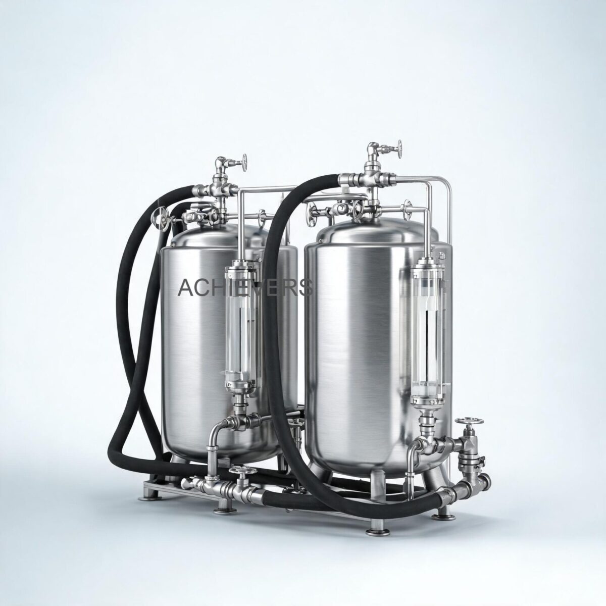
To specify a batching system for industrial environments, procurement engineers must match the system capabilities to fluid dynamics and site constraints. The data below outlines the technical specifications for the Achievers brand batching system manufactured by Lumen Instruments.
| Parameter | Specification | Engineering Notes |
| :— | :— | :— |
| System Brand | Achievers | Manufactured with optimum quality materials |
| Primary Application | Lube oils, diesel oil, transmission liquids | Automotive assembly stage filling, heavy equipment |
| Measurement Technology | Oval Gear Meter | Positive displacement, ideal for viscous media |
| Maximum Flow Capacity | 60 Litre/Min | Sized for rapid barrel/vehicle filling without foaming |
| Volumetric Exactness | ±0.5 % | Under steady state conditions. Superior to manual dipsticks |
| Operating Voltage | 220 V AC | Integrated power supply for controller, pump, and solenoid |
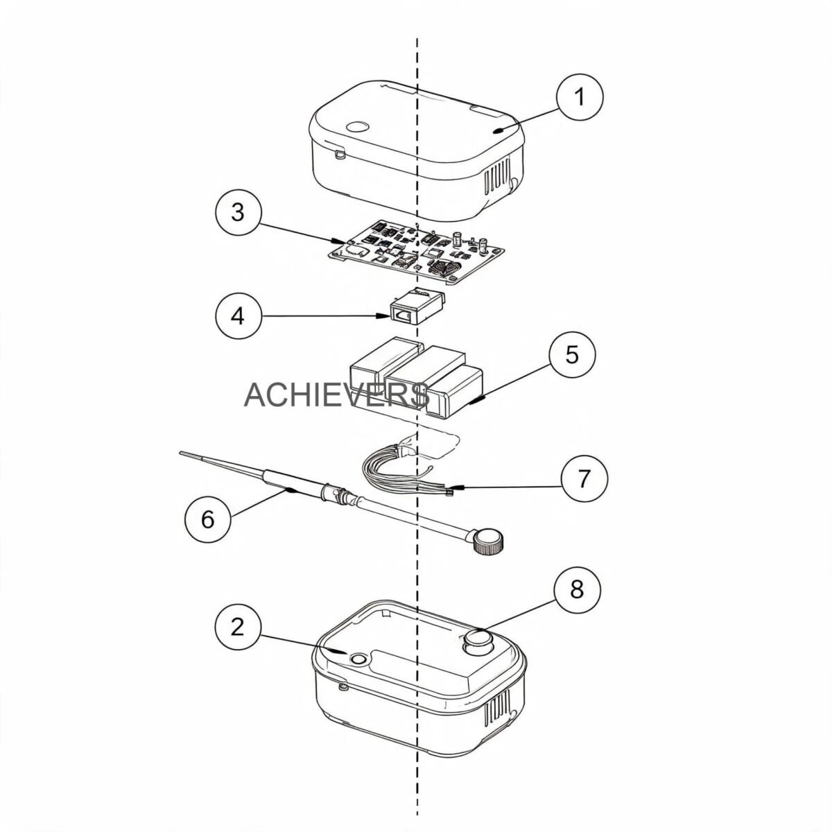
| Integrated Components | Pump, Flow Sensor, Controller, Solenoid | Complete end-to-end turnkey dispensing loop |
| Variable Presets | Multiple configurable batch sizes | Allows one station to fill different engine or gearbox models |
| Material Build | Erosion/Corrosion Resistant | Designed to handle varying chemical compositions of industrial lubes |
| Output Type | Direct valve actuation via relay | Fast-acting response for precision cut-off |
Technology Comparison: Batching Meter Selections
For plant managers exploring various metering technologies for batch lines, it is vital to understand why oval gear technology is preferred for lubricants over other common meters like Positive Displacement Flow Meters of different types, Turbine, or Electromagnetic meters.
| Parameter | Oval Gear (PD) | Turbine | Electromagnetic |
| :— | :— | :— | :— |
| Best Fluid Match | High-viscosity (Lube oil, diesel) | Low-viscosity (Water, light solvents) | Conductive fluids (Water, slurry) |
| Viscosity Immunity | Excellent (Accuracy improves with thickness) | Poor (Requires recalibration if fluid changes) | Excellent (But cannot measure oils) |
| Upstream Piping Req. | None (0D/0D) | High (10D upstream, 5D downstream) | Moderate (5D upstream, 3D downstream) |
| Pressure Drop | Moderate to High | Low to Moderate | Zero (Unobstructed bore) |
| Batch Cut-off Precision | Extremely High (Discrete volumes) | Moderate (Rotor coasting causes errors) | High |
"When to Use This Technology" Decision Matrix
- USE Oval Gear Batching Systems WHEN: Dispensing heavy transmission fluids, motor oils, or diesel fuel where viscosity fluctuates with ambient temperature.
- USE Oval Gear Batching Systems WHEN: Installation space is tight, and you cannot provide straight pipe runs before and after the meter.
- DO NOT USE WHEN: Batching highly abrasive slurries (particulates will lock the precision gear clearances) or electrically conductive water-based chemicals (where an electromagnetic meter is maintenance-free).
3. Performance Characteristics and Error Sources
Even with a ±0.5% accuracy rating, real-world Indian industrial conditions can introduce severe measurement errors if engineers do not account for fluid dynamics and site variables.
Viscosity Shifts and "Slip" Error
Slip is the phenomenon where a tiny amount of fluid bypasses the measuring gears through the microscopic clearances between the gear teeth and the meter body.
- High Viscosity (Winter / Heavy Oils): Thick fluids naturally seal these clearances. Slip is nearly zero, yielding exceptionally high accuracy.
- Low Viscosity (Summer / Light Diesel): Thin fluids slip through the gaps more easily, especially at high back-pressures.
Mitigation: If you use the same batching system for diesel in the summer and heavy transmission fluid in the winter, the K-factor must be recalibrated for each fluid type to compensate for the varying slip factor.
Air Entrainment
Oval gear meters measure volume, regardless of whether that volume is liquid or air. In many Indian facilities, suction-side pump cavitation, empty supply tanks, or leaky pipe joints introduce air bubbles into the liquid stream. The meter will read this air as dispensed fluid, resulting in "short batches" where the physical liquid delivered is less than the preset amount.
Mitigation: Always install an air eliminator (de-aerator) upstream of the flow meter in any batching system pulling from underground or distant bulk tanks.
Pulsating Flow
While positive displacement meters handle pulsation better than turbine meters, aggressive hydraulic hammering from poorly sized pumps can cause the internal gears to momentarily surge past the sensor read-rate, dropping pulses.
Mitigation: The system’s integrated continuous-duty pump is matched to the 60 L/Min capacity to ensure steady, non-pulsating delivery. Avoid tampering with pump bypass valves inappropriately.
4. Materials and Chemical Compatibility
The wetted parts of the metering block, solenoid, and pump must be chemically compatible with the media being dispensed. Using an incorrect seal material (like natural rubber with hydrocarbons) leads to catastrophic swelling, gear lock-up, and leakage.
| Industrial Fluid | Compatibility with Standard Batching System | Engineering Notes |
| :— | :— | :— |
| Diesel Fuel (HSD) | Excellent | Natural lubrication extends gear life. |
| Engine Oil (15W40, etc.) | Excellent | Optimal viscosity for highest volumetric accuracy. |
| Transmission Fluids (ATF) | Excellent | Thick media seals internal clearances perfectly. |
| Hydraulic Oil | Excellent | Monitor for particulate contamination; use Y-strainer. |
| Kerosene | Good | Lower viscosity means slightly higher slip; calibrate on-site. |
| Water / RO Water | Poor / Incompatible | Causes rapid internal rusting and lacks lubricity for gears. |
| Petrol / Gasoline | Not Recommended | Requires specialized explosive-proof (PESO/ATEX) certifications. |
| Strong Acids/Alkalis | Incompatible | Corrodes standard body and internals; requires PTFE/Hastelloy systems. |
5. Calibration, Verification, and Certification
Maintaining the ±0.5% exactness requires regular proving. In Indian automotive or heavy manufacturing plants, adhering to Legal Metrology or internal ISO 9001 QA standards dictates that batching lines be verified bi-annually.
Calculating the Meter Factor (K-Factor)
The K-Factor is the number of pulses generated per unit of volume (Pulses/Litre). If a batch is short or long, the K-Factor in the controller must be adjusted.
New K-Factor = (Actual Volume Dispensed / Displayed Volume on Controller) * Current K-Factor
Step-by-Step Field Verification Procedure
To accurately verify and recalibrate your liquid batching system on-site, execute the following engineering procedure:
- Isolate and Prepare: Ensure the fluid supply tank has sufficient capacity and is at normal operating temperature to account for thermal expansion.
- Setup Proving Receptacle: Place an officially certified, calibrated volumetric proving can (e.g., 20 Liters or 50 Liters) beneath the dispensing nozzle.
- Prime the System: Run a small preliminary batch (unmeasured) to purge all atmospheric air from the pump, meter, and hoses. Air pockets will invalidate the test.
- Set the Preset: Enter a precise batch amount into the controller that exactly matches the proving can's nominal volume (e.g., 20.00 Liters).
- Execute Dispense: Start the batching cycle. Observe the solenoid valve's two-stage closure (if equipped) to ensure it shuts cleanly without water hammer.
- Read Actual Volume: Wait for fluid froth to settle in the proving can. Read the exact dispensed volume from the certified sight glass.
- Calculate Error: If the display reads 20.00L but the can holds 19.80L, the system is over-reporting. Calculate the new K-Factor using the formula above.
- Update and Retest: Enter the newly calculated K-Factor into the controller's engineering menu and repeat steps 4 through 6 to confirm the error is now within ±0.5%.
Batching accuracy directly impacts bottom-line profitability. By coupling a robust oval gear measuring chamber with intelligent preset pulse logic and precisely staged solenoid valves, facilities can eliminate the human error inherent in manual fluid transfer. For those managing complex fleets or heavy machinery, standardizing your Diesel Flow Meters and batch dispensing equipment guarantees that every drop of expensive inventory is accounted for, documented, and utilized efficiently.
*
FAQ
Q: Can this batching system handle both diesel and thick gear oil without hardware changes?
A: Yes, the oval gear meter and integrated pump can handle both. However, because gear oil has a drastically different viscosity than diesel, you must recalibrate the controller's K-factor when switching fluids to maintain the ±0.5% accuracy, as the "slip" factor changes.
Q: What happens to the batching accuracy during power fluctuations common in Indian industrial zones?
A: The system operates on 220V AC. Severe voltage drops can delay the mechanical response time of the solenoid valve, leading to slight over-dispensing. For areas with highly unstable power grids, utilizing a CVT (Constant Voltage Transformer) or UPS for the batch controller is highly recommended.
Q: Is a strainer necessary upstream of the batching system?
A: Absolutely. Oval gear meters have extremely tight mechanical clearances to ensure high accuracy. Even small particulates, welding slag, or rust from old Indian storage barrels can lock the gears. A 100-micron Y-strainer is a mandatory installation requirement.
Q: Why does my batching system dispense slightly less liquid than the preset amount indicates?
A: This is almost always caused by air entrainment. If air enters the suction line through a loose fitting or low tank levels, the meter measures the air bubbles as fluid volume. Installing an air eliminator before the meter resolves this issue.
Q: What is the maximum flow rate, and can it be adjusted?
A: The rated capacity of this system is 60 Litre/Min. While the mechanical pump runs at a fixed speed, the flow rate will naturally decrease slightly as fluid viscosity increases (e.g., pumping cold 80W90 gear oil versus warm diesel).
Q: Does the system require regular maintenance?
A: Maintenance is minimal but critical. The primary tasks are cleaning the upstream Y-strainer monthly, checking the solenoid diaphragm for wear annually, and verifying volumetric accuracy with a certified proving can every 6 to 12 months depending on usage volume.
Q: Can this system be used to batch water or chemical solvents?
A: No. The internal gears of the standard system rely on the lubricity of hydrocarbons (diesel, lube oils) to operate smoothly. Pumping water will cause internal oxidation (rust) and rapidly destroy the measurement chamber.
If you are upgrading your facility's fluid transfer lines and need to eliminate manual dispensing errors, accurate engineering sizing is the first step. Contact our technical sales team today with your fluid type, required batch volume, and site conditions, and we will configure the exact Liquid Batching Systems required for your application.