
In capital-intensive industries like mining, marine, offshore oil and gas, and power generation, accurate fuel management is critical. Diesel fuel represents one of the largest operational expenses, and even a 2% measurement error on a multi-megawatt generator or heavy earth-moving vehicle can lead to thousands of dollars in unallocated costs. Unfortunately, engineers frequently encounter discrepancies when measuring diesel engine net consumption, specifically when calculating the difference between supply lines and return lines.
Downtime for diagnostics costs money. When dual-sensor Fuel Consumption Meters report incorrect net usage, plant managers and maintenance engineers often rush to replace the hardware. However, in our experience across global industrial sites, more than 80% of these errors originate not from mechanical failure, but from return-line aeration, thermal expansion mismatch, or incorrect sensor pairing. This highly detailed guide provides a systematic fault tree to isolate installation, calibration, and signal issues so you can restore accuracy and maintain API and ISO compliance without unnecessary procurement costs.
1. Quick Reference: How Fuel Consumption Meters Work
To diagnose a flow system, you must first understand its thermodynamic and mechanical baseline. Modern diesel engines and generators do not consume all the fuel delivered by the transfer pump. To cool the fuel injectors and maintain optimal rail pressure, engines circulate a large volume of diesel, combusting only a fraction and returning the excess to the primary tank.
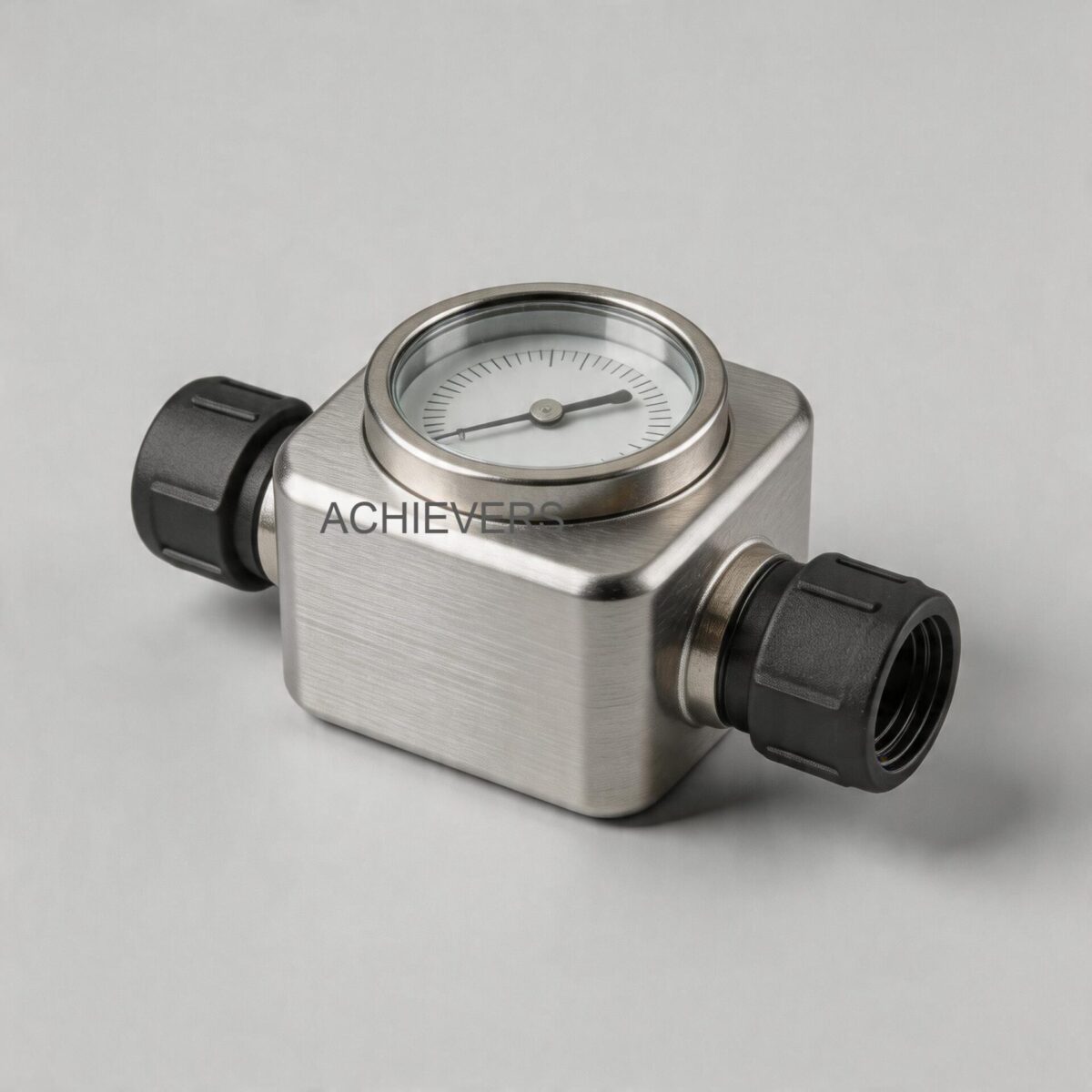
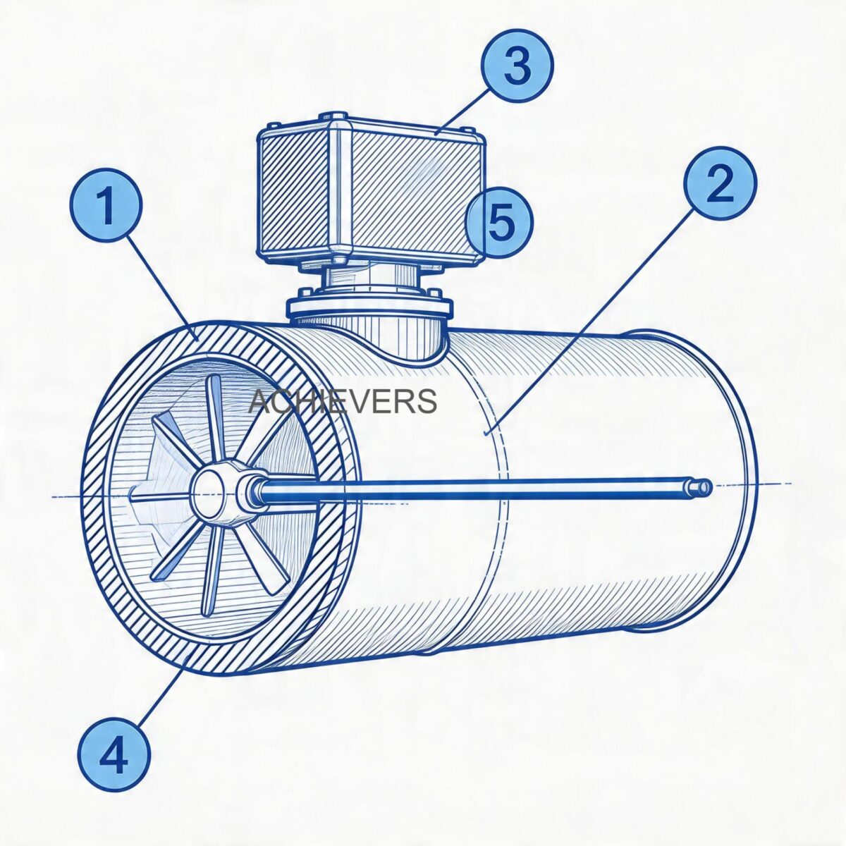
Fuel Consumption Meters rely on a differential measurement principle using two positive displacement sensors (typically oval gear) and a central microprocessor or fuel calculator.
The Mathematical Principle:
Net Fuel Consumption (C) = Fuel Supply to Engine (A) – Fuel Returned from Engine (B)
The accuracy of this calculation requires identical precision on both sides of the equation. Our systems use an aluminum anodized oval gear detecting component, which operates on the positive displacement principle. As fluid passes through the chamber, it forces the meshed gears to rotate. Each rotation displaces a precise, finite volume of liquid, which is converted into a high-resolution pulse output via a magnetic pickup.
Core Specifications of the System:
- Operating Principle: Positive Displacement (Oval Gear)
- Sensor Accuracy (Standard Installation): 0.1% Full Scale Deflection (FSD)
- System Accuracy (Net Calculation): 0.5% of genuine consumption
- Power Supply: 5 Vdc to 24 Vdc (compatible with 5Vdc to 29Vdc engine batteries)
- Output Options: RS-485, RS-232, or pulse yield for GPS/GPRS tracking
- Measurement Units: Liters, Gallons, Cubic Meters
2. Technology Comparison & Decision Matrix
No single flow measurement technology is perfect for every global application. When measuring heavy-duty diesel engines, engineers must choose between Positive Displacement (Oval Gear), Turbine, and Coriolis meters. Here is how they compare in a differential fuel consumption setup.
Technology Comparison Table
| Parameter | Positive Displacement (Oval Gear) | Turbine Flow Meters | Coriolis Mass Flow Meters |
| :— | :— | :— | :— |
| Primary Measurement | Volumetric | Velocity | Mass |
| Accuracy Rating | 0.1% to 0.5% | 0.5% to 1.0% | 0.1% to 0.2% |
| Viscosity Immunity | Excellent (Improves with viscosity) | Poor (Requires recalibration) | Excellent |
| Return Line Suitability | High (Handles low/pulsating flows) | Low (Fails on pulsating flow) | High (But expensive for dual lines) |
| Pressure Drop | Moderate (Increases with viscosity) | Low | Moderate to High |
| Capital Cost (Dual Setup) | Moderate | Low | Extremely High |
| Aeration Sensitivity | Moderate (Measures air as volume) | High (Overspins rapidly) | Low (Rejects entrained gas) |
When to Use This Technology: Decision Matrix
- Use Fuel Consumption Meters (Oval Gear PD): When measuring net fuel usage on heavy machinery, marine vessels, and generators where flow pulsates, viscosity varies slightly with temperature, and capital budgets cannot accommodate dual Coriolis setups. (Read more about our Positive Displacement Flow Meters for similar applications).
- Use Turbine Meters: For steady-state, clean, low-viscosity bulk fluid transfer with no pulsation.
- Use Coriolis Meters: For custody transfer applications requiring mass measurement under extreme, constantly fluctuating API gravity conditions.
3. Troubleshooting Matrix
When a dual-sensor differential meter reports incorrect data, the fault usually lies in how the return line is managed. The following matrix isolates common symptoms across mechanical, hydraulic, and electrical domains.
| Symptom | Likely Cause | Diagnosis Steps | Fix |
| :— | :— | :— | :— |
| Negative Net Consumption | Swapped sensor wiring or swapped plumbing | Verify physical flow direction against sensor arrows. Check A and B inputs on calculator. | Reverse wiring inputs A and B on the fuel calculator or reinstall sensors correctly. |
| Spiking / Erratic Net Consumption | Entrained air / aeration in the return line | Observe return fuel for foaming. Check injector spill ports for vacuum leaks. | Install an air eliminator / degasser upstream of the return sensor. |
| Under-reporting Consumption | Thermal expansion of return fuel | Measure supply temp vs return temp. (Fuel expands ~0.84 liters per 1,000L per °C). | Apply thermal compensation factors in the PLC/calculator or install a fuel cooler. |
| Zero Reading on Display | Loss of power or broken comms link | Measure voltage across power terminals (Should be 5 Vdc to 24 Vdc). Check RS-485. | Restore engine battery power connection; verify 5-29 Vdc supply. |
| Steady Over-reporting | Bypass valve open or leaking | Isolate the mechanical bypass line. | Close or rebuild the bypass valve; ensure 100% of fuel passes through meters. |
| High Pressure Drop / Engine Stalling | Blocked Y-Strainer | Check pressure differential across the inlet Y-strainer. | Remove and clean the Y-type fuel strainer/mesh. |
| Drifting Calibration | Wear on oval gears from contamination | Extract sensor. Inspect aluminum anodized gears for scoring. | Replace gears; ensure filtration is strictly adhered to upstream. |
| No Pulse Yield to GPS/GPRS | Dead output board or mismatched protocol | Oscilloscope or multimeter on pulse output to check for square wave. | Reconfigure digital yield for RS-232/RS-485 in the meter settings. |
| Low Flow Cutoff Not Registering | Mismatched sensor size for HP rating | Check HP rating of engine against sensor model (e.g., using CE-020 for a 200 HP engine). | Resize sensor. Use CE-006 for <200 HP engines to capture low flow. |
| Meter Noise / Chattering | Cavitation due to suction restriction | Check vacuum pressure upstream of the supply transfer pump. | Increase pipe diameter, clean strainers, ensure NPSHa > NPSHr. |
4. Step-by-Step Field Diagnosis Procedure
Do not pull the hardware off the pipe until you have completed this diagnostic fault tree. You will need a digital multimeter, an infrared thermometer, and basic hand tools.
Step 1: Verify Sensor Sizing and Pairing against Engine HP
A frequent cause of low-flow inaccuracy is installing an oversized meter. Verify your engine's horsepower and check the installed hardware against the FCM sizing matrix:
- FCM:006 (CE-006 sensors): Up to 200 HP Diesel Engines
- FCM:008 (CE-008 sensors): 200 HP to 400 HP
- FCM:012 (CE-012 sensors): 400 HP to 1000 HP
- FCM:020 (CE-020 sensors): 1000 HP to 1500 HP
- FCM:025 (CE-025 sensors): 1500 HP to 2000 HP
If a CE-025 is installed on a 400 HP engine, it will fail to accurately register the low flow rates at idle.
Step 2: Validate System Voltage and Grounding
Supply fluctuations cause microprocessor errors. The meter requires a clean 5 Vdc to 24 Vdc (board tolerance allows up to 29 Vdc from an engine battery). Measure the voltage at the fuel calculator terminals. Ensure the ground is tied directly to the chassis to prevent alternator noise from corrupting the digital pulse yield.
Step 3: Check for Return Line Aeration (The Most Common Fault)
Diesel fuel returning from the injectors is hot and highly agitated, often foaming. Oval gear meters are volumetric; they will measure a bubble of air exactly as they measure a drop of liquid. If net consumption is erratically high, crack a bleed valve upstream of the return sensor to check for foaming. An air eliminator must be installed if aeration is present.
Step 4: Execute a Thermal Expansion Check
Engineering Calibration Note: Volumetric positive displacement meters do not inherently account for fluid density changes. Supply fuel might be 25°C, but return fuel from the cylinder head can exceed 65°C. Diesel expands by roughly 0.084% per degree Celsius. If you supply 100 Liters at 25°C, and 90 Liters returns at 65°C, the returned volume has expanded. The meter measures the physically larger volume, artificially reducing your calculated net consumption. Check the delta-T with an infrared thermometer and ensure your calculator or PLC is programmed with the correct thermal compensation algorithm.
Step 5: Inspect the Y-Type Fuel Strainer
Both the inlet and return sensors rely on a clean Y-type strainer. Isolate the lines and remove the strainer baskets. Debris here causes pressure drops that can induce localized cavitation, which the meter registers as false volume.
Step 6: Confirm Calibration Factors (K-Factor)
Access the fuel calculator's menu. Verify that the K-Factor (pulses per liter) programmed into the unit matches the K-Factor stamped on the metal data plates of both the CE inlet and CE return sensors.
Step 7: Isolate Bypass Loops
Check the mechanical P&ID (Piping and Instrumentation Diagram) of the generator. If there is a pressure relief valve or day-tank bypass loop located between the supply meter and the return meter, fuel is bypassing the system. The supply meter and return meter must be the absolute boundaries of the fluid loop.
Step 8: Perform a Static Volumetric Draw Test
If all above checks pass, disconnect the return line from the main tank and route it into a certified, calibrated proving bucket. Run the engine. Calculate Supply minus Prover Bucket Volume. This isolates the return sensor entirely and validates the mechanical accuracy of the supply sensor.
5. Installation and Setup Errors That Cause Ongoing Problems
The rigorous vibration, extreme ambient temperatures, and complex plumbing of heavy equipment applications mean installation errors will inevitably manifest as measurement faults. Check for these common deployment failures:
| Installation Error | Symptom | Correction |
| :— | :— | :— |
| Mounting Sensors on Engine Block | Excessive vibration causes erratic pulse generation and false high readings. | Mount sensors on the vehicle chassis or a vibration-isolated bracket away from the engine block. |
| Vertical Mounting with Downward Flow | Air pockets become trapped in the oval gear chamber, causing intermittent dry-running. | Mount meters horizontally. If vertical mounting is necessary, flow must travel upwards to purge air. |
| Absence of Air Eliminators | Aerated return fuel causes the meter to over-register returned volume, lowering net consumption. | Install a mechanical air eliminator/degasser prior to the return line flow sensor. |
| Improper Strainer Mesh Size | Strainer is too fine, causing cavitation; or too coarse, allowing particulates to jam the gears. | Use the manufacturer-specified Y-type fuel strainer (typically 100-200 micron for diesel). |
| Dead-heading the Return Line | Pressure spikes damage the aluminum anodized internal gears. | Ensure return lines flow freely to the tank with zero back-pressure restrictions. |
| Routing Sensor Cables with High Voltage | Electromagnetic interference (EMI) corrupts the low-voltage pulse signal to the calculator. | Route sensor cables in separate, shielded conduits away from alternator/generator power lines. |
6. Preventive Maintenance to Avoid Recurrence
To maintain the stated 0.1% FSD precision across the lifecycle of a high-capacity heavy duty marine diesel engine or mining dumper, standard preventive maintenance is non-negotiable.
- Weekly: Check the inline Y-strainers. In industrial environments with high dust or poor fuel bunkering, strainers clog rapidly.
- Monthly: Inspect the data cables for chafing. Ensure the RS-485 / RS-232 connections remain sealed against moisture, particularly in offshore marine environments.
- Bi-Annually: Perform a visual inspection of the fluid path. Look for micro-leaks at the flange or thread connections, as suction-side leaks will draw air into the system and destroy measurement accuracy.
- Annually: Extract the oval gears. Clean the aluminum anodized detecting components using a non-corrosive solvent. Do not use wire brushes. Verify the gears spin freely on their shafts.
(For parallel maintenance strategies on transfer systems, refer to our guide on Diesel Flow Meters).
7. When to Call Service vs. Fix Yourself
Knowing your engineering limits saves time. Many faults are field-serviceable, while others require factory recalibration.
Fix Yourself:
- Clearing blockages in the Y-strainer.
- Resolving aeration issues by installing air eliminators.
- Correcting wiring polarity or shielding issues.
- Re-entering K-Factors into the digital display.
- Adjusting thermal compensation math in your external PLC.
Call Factory Service:
- If the aluminum oval gears are physically scored or damaged from particulate ingress (requires replacement and factory recalibration).
- If the magnetic pickup coil fails to yield a pulse when mechanically rotated.
- If the main fuel calculator PCB is exposed to voltage spikes exceeding 30 Vdc and fails to power on.
- If you require custom CE-025 sensor manifolds for engine capacities exceeding 2000 HP.
FAQ
Q: Why is my net consumption reading negative?
A: A negative reading almost always means the supply and return lines are physically swapped, or the A and B pulse inputs are wired backward into the central calculator. Verify the flow direction arrows on the sensor bodies.
Q: Can I use standard water meters for my diesel return lines?
A: Absolutely not. Diesel engines require fuel meters utilizing positive displacement principles (like oval gear) that are immune to viscosity changes and contain seals rated for hydrocarbons. Standard meters will suffer elastomer degradation and lack the high-resolution accuracy required for differential math.
Q: Does fuel temperature really affect my measurement that much?
A: Yes. Diesel expands at approximately 0.084% per degree Celsius. If your supply is drawn from a cold tank and returned from a hot engine block, the volume expands. Without thermal compensation, your meter will subtract a larger return volume, making your engine appear more fuel-efficient than it actually is.
Q: How do I know if aeration is causing my erratic readings?
A: Install a clear sight-glass temporarily in the return line. If you see bubbles, foaming, or a milky consistency in the fuel, air is passing through the positive displacement meter. An air eliminator must be installed immediately.
Q: What is the maximum operating voltage for the fuel calculator?
A: The system accepts power from 5 Vdc to 24 Vdc standard, but is engineered to handle onboard power supplies direct from engine batteries up to 29 Vdc. Ensure clean, regulated power to avoid digital signal corruption.
Q: Can I connect these meters directly to my fleet GPS tracking system?
A: Yes. The fuel calculator optionally provides RS-485, RS-232, or a digital pulse yield output. This easily interfaces with standard GPS and GPRS modems for remote telemetry of total fuel supply, return, and net consumption.
Q: How frequently should the positive displacement meters be recalibrated?
A: In clean, well-filtered environments, oval gear meters hold their calibration for years. However, ISO standard compliance typically requires annual verification. If the K-Factor drifts, it usually indicates mechanical wear on the gears requiring component replacement.
To request technical specifications, CAD models, or pricing for differential measurement systems, contact our engineering team today. Please include your engine horsepower, maximum flow rates (supply and return), operating temperatures, and preferred digital output protocol so we can size the appropriate CE-series sensors for your exact application.