
For instrumentation engineers, plant managers, and procurement heads across Indian industrial sectors—from petrochemical refineries in Gujarat to wastewater treatment facilities in Maharashtra—selecting the right flow measurement technology is a high-stakes decision. With capital expenditures ranging from ₹20,000 to over ₹10,00,000 per measurement node, relying on vendor marketing brochures is a recipe for operational failure. You need to understand the fundamental physics, electronic signal processing, and material science behind the instrument.
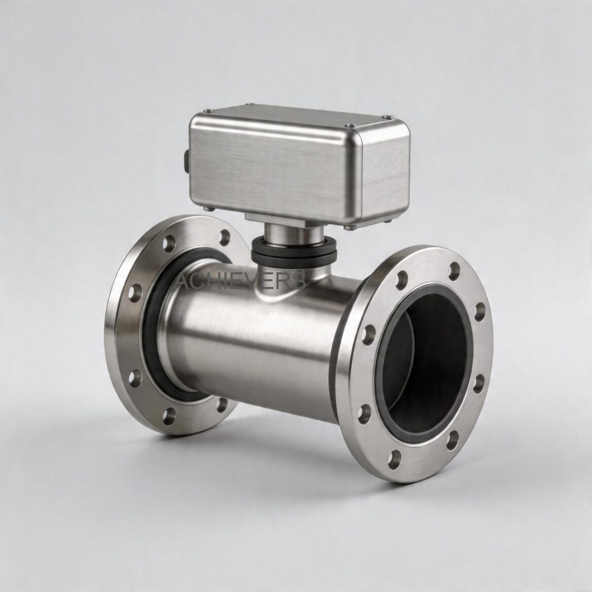
Among the most universally deployed technologies in conductive fluid applications are Electromagnetic Flow Meters. Unlike mechanical meters, these devices feature a full-bore design with no moving parts, resulting in zero pressure drop and immunity to variations in density, viscosity, temperature, and pressure. However, treating these instruments as simple "plug-and-play" black boxes often leads to noise interference, electrode fouling, and unacceptable measurement uncertainty, especially under challenging Indian site conditions characterized by 50Hz voltage fluctuations, stray ground currents, and high ambient temperatures.
This technical deep-dive deconstructs the operation of Electromagnetic Flow Meters. We will trace the measurement chain from the physics of Faraday’s Law and the electronic architecture of Pulsed DC excitation, to electrode sensing and microprocessor linearization. By understanding these internal mechanics, industrial buyers can accurately specify the right liner materials, configure the 4-20 mA outputs, and ensure error-free installation of Electromagnetic Flow Meters in their facilities.
1. Working Principle: How Electromagnetic Flow Meters Operate
At the core of an electromagnetic flow meter (often called a mag meter) is Michael Faraday’s Law of Electromagnetic Induction. The principle states that when a conductive fluid moves through a magnetic field, a voltage is induced in the fluid. This induced voltage is directly proportional to the velocity of the moving fluid.
The mathematical relationship is defined by the engineering formula:
E = k * B * D * V
Where:
- E is the induced voltage generated in the fluid.
- k is the instrument constant.
- B is the magnetic field strength generated by the meter's coils.
- D is the inner diameter of the flow tube (distance between electrodes).
- V is the average velocity of the fluid.
Because the magnetic field strength (B) and the pipe diameter (D) are fixed and known, the induced voltage (E) becomes strictly a linear function of the fluid velocity (V). The volumetric flow rate (Q) is then calculated by multiplying this velocity by the cross-sectional area of the pipe (Q = V * A).
The Role of Pulsed DC Excitation
Early generations of mag meters utilized AC (Alternating Current) excitation directly from the mains power. While this prevented electrode polarization, it resulted in severe zero-drift and made the meter highly susceptible to 50Hz electromagnetic noise—a massive problem in Indian industrial sites with noisy power grids.
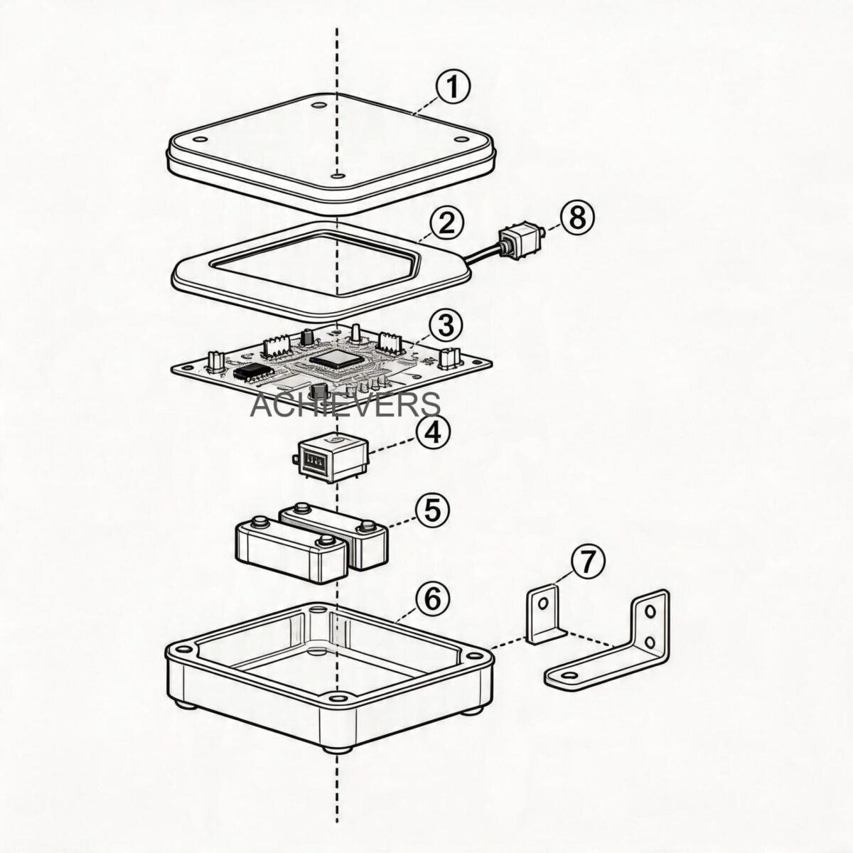
Modern micro-controller based transmitters, such as those manufactured by Lumen Instruments, utilize 'Pulsed DC' technology. The transmitter sends a precisely regulated pulsed direct current to the magnetic coils, alternating the polarity at a specific low frequency (typically 6.25 Hz or 12.5 Hz).
During the "off" or stable phase of the pulse, the microprocessor samples the baseline electrochemical noise present on the electrodes. During the "on" phase, it samples the combined noise and flow-induced voltage. By subtracting the baseline noise from the total signal, the microprocessor isolates the pure flow signal. This dual-sampling technique delivers exceptional zero-point stability, high measuring accuracy (+/- 0.5% standard), and high noise rejection, outputting a highly stable 4-20 mA DC signal linearly proportional to the volumetric flow.
2. Complete Technical Specifications
Specifying a mag meter requires aligning the instrument’s physical and electrical parameters with your process conditions. Below are the comprehensive engineering specifications for industrial-grade electromagnetic flow meters, encompassing flanged, triclover (sanitary), and battery-operated variants.
| Parameter | Specification Details | Engineering Notes |
| :— | :— | :— |
| Pipe Size Range | DN 15 to DN 1000 (Flange) <br> DN 15 to DN 80 (Triclover) <br> DN 15 to DN 300 (Battery Operated) | Covers applications from small dosing lines to large municipal water mains. |
| Measuring Range | 0.2 to 2800 m3/h (Flange) <br> 0.2 to 180 m3/h (Triclover) | Highly dependent on pipe diameter. Velocity range is typically 0.3 m/s to 10 m/s. |
| Accuracy Class | +/- 0.5% of reading (Standard) <br> +/- 0.2% of reading (Optional) <br> +/- 1.0% (Battery Operated) | High accuracy guaranteed according to the linear measurement principle. |
| Minimum Conductivity | Greater than or equal to 5 µS/cm | Critical limitation. Cannot measure demineralized water or hydrocarbons. |
| Electrode Materials | 316 L SS, Hastelloy C (Hc), Hastelloy B (Hb), Titanium (Ti), Tantalum (Ta) | Must be matched to fluid corrosivity to prevent pitting and signal degradation. |
| Liner Materials | Neoprene, PTFE, PFA, F46 | Isolates the flow tube to prevent short-circuiting the induced voltage. |
| Analog Output | 4 – 20 mA DC | Linearly proportional to volumetric flow. Used for PLC/DCS integration. |
| Digital Output | RS485 / HART / MODBUS (Digital transmission) | Enables remote diagnostics and multi-variable transmission. |
| Temperature Rating | Medium: -10°C to 150°C <br> Environment: 0°C to 55°C | Ambient temp max of 55°C is crucial for outdoor Indian summer installations. |
| Power Supply | 220VAC 50Hz, 24 VDC <br> 3.6 V Lithium Battery (Stand-alone) | Max power consumption <= 15W. Low power draw suitable for solar-backed sites. |
| Ingress Protection | IP65, IP67 | IP67 is mandatory for installations exposed to monsoon flooding or washdowns. |
3. Performance Characteristics and Error Sources
While electromagnetic flow meters offer a free pipe cross-section and are largely immune to changes in fluid density and viscosity, achieving their rated +/- 0.5% accuracy requires managing several field variables.
1. Minimum Conductivity Limits
The fluid must be conductive. The industry standard threshold is 5 µS/cm. Normal tap water, wastewater, agricultural slurry, and acids possess conductivities well above this limit (often 50 to 50,000 µS/cm). However, boiler feed water, Reverse Osmosis (RO) permeate, and pure hydrocarbons (like diesel or thermic fluid) fall below 1 µS/cm. In such low-conductivity applications, the internal resistance of the fluid is too high, and the electrodes cannot read the induced voltage. For hydrocarbons, engineers must pivot to Turbine Flow Meters or Positive Displacement Flow Meters.
2. Entrained Air and Partially Filled Pipes
Mag meters measure velocity. If a pipe is only 80% full, the meter will assume it is 100% full and multiply the velocity by the full cross-sectional area, resulting in heavily inflated flow readings. Similarly, if there are entrained air bubbles in the fluid (due to poor pumping or cascading drop-offs), the meter measures the volume of the air as if it were fluid. To mitigate this, meters must be installed in U-shaped piping sections or vertical upward flows to guarantee a fully flooded tube.
3. Stray Grounding Currents
Indian process plants often suffer from poor electrical earthing. Because the induced voltage (E) is measured in millivolts, any stray AC or DC current traveling through the piping system can swamp the flow signal. When installing mag meters in non-conductive PVC, HDPE, or FRP pipes, grounding rings (earthing rings) made of compatible stainless steel must be installed on both sides of the meter to create a localized, noise-free equipotential zone.
4. Materials and Chemical Compatibility
The longevity of a mag meter depends entirely on specifying the correct wetted parts. The fluid comes into contact with only two components: the insulating liner and the sensing electrodes.
Choosing incorrect materials for aggressive chemicals will destroy the meter within weeks, a costly mistake for procurement heads. Below is an engineering selection matrix for Indian industrial applications:
| Process Fluid / Application | Recommended Liner | Recommended Electrode | Engineering Justification |
| :— | :— | :— | :— |
| Raw Water / Sewage | Neoprene / Hard Rubber | 316 L Stainless Steel | Cost-effective. Neoprene handles mild abrasion and ambient temperatures well. |
| Drinking Water (Municipal) | PTFE / PFA | 316 L Stainless Steel | PTFE ensures hygienic, food-grade compliance with no leaching. |
| Highly Abrasive Slurry (Mining) | Polyurethane / Neoprene | Hastelloy C (Flush) | Polyurethane resists severe abrasion. Hastelloy resists pitting from sharp particulates. |
| Sulfuric Acid (H2SO4, 98%) | PTFE / F46 | Tantalum (Ta) | Tantalum is inert to concentrated acids. PTFE resists extreme chemical attack. |
| Hydrochloric Acid (HCl) | PTFE / PFA | Tantalum / Titanium | 316L will dissolve rapidly in HCl. Ta or Ti is mandatory. |
| Sodium Hydroxide (Caustic Soda) | PTFE | Hastelloy B / Platinum | High pH basic solutions require specialized Hastelloy alloys. |
| Food & Beverage (Milk, Beer) | PFA | 316 L (Sanitary finish) | Uses Triclover fittings. PFA handles high-temperature CIP (Clean-In-Place) steam. |
| Hydrocarbons / Diesel fuel | NOT APPLICABLE | NOT APPLICABLE | Conductivity < 5 µS/cm. Use Turbine or Positive Displacement Flow Meters instead. |
5. Technology Comparison: The Decision Matrix
No single flow meter handles every application. Knowing when to deploy a mag meter versus alternative technologies is a hallmark of good instrumentation engineering.
| Feature / Parameter | Electromagnetic Flow Meter | Turbine Flow Meter | Vortex Flow Meter | Positive Displacement |
| :— | :— | :— | :— | :— |
| Measuring Principle | Faraday's Law (Electromagnetic) | Rotor speed proportional to velocity | Von Kármán effect (Bluff body) | Capturing fixed fluid volumes |
| Conductivity Req. | Must be >= 5 µS/cm | None (ideal for non-conductives) | None | None |
| Pressure Drop | Zero (Full bore, no obstruction) | Medium (Rotor obstruction) | Low to Medium (Bluff body) | High (Mechanical clearances) |
| Viscosity Tolerance | High (Independent of viscosity) | Low (Calibration shifts heavily) | Low to Medium | Very High (Better at high visc.) |
| Moving Parts | None | Yes (Rotor and bearings) | None (Sensor only) | Yes (Gears, vanes, or lobes) |
| Best Used For | Water, Wastewater, Slurries, Acids | Diesel, Solvents, Clean fluids | Steam, Gases, Utility water | Heavy Fuel Oil, Resins, Syrups |
When to Use Electromagnetic Meters:
Use when handling conductive liquids, corrosive chemicals, or slurries where pressure drop must be avoided and minimal maintenance is desired.
When NOT to Use Electromagnetic Meters:
Do not use for gases, steam, compressed air, or non-conductive liquids like diesel, petrol, lube oil, and demineralized (RO) water.
6. Installation, Calibration, and Verification Procedure
Correct installation piping geometry is just as critical as the meter's internal calibration. A factory-calibrated meter will fail in the field if flow profiles are distorted by valves or elbows.
Follow this strict engineering procedure for installing and commissioning mag meters in industrial plants:
- Verify Line Geometry and Flow Profile: Ensure there is a minimum straight pipe run of 5 x Pipe Diameter (5D) upstream and 3 x Pipe Diameter (3D) downstream from the meter flanges. This stabilizes the turbulent flow profile before it hits the electrodes.
- Ensure a Fully Flooded Tube: Install the meter in a vertical pipe section with fluid flowing upwards, or at the lowest point of a horizontal U-trap. Never install at the highest point of a pipeline where air pockets accumulate, or in a downward vertical pipe where gravity may cause a partially filled pipe.
- Align Electrode Axis Horizontally: When mounting horizontally, ensure the imaginary line connecting the two measuring electrodes is parallel to the ground (horizontal). If mounted vertically, gas bubbles will hit the top electrode, and sediment will bury the bottom electrode, causing signal loss.
- Install Grounding Rings (if required): If the pipeline is made of PVC, HDPE, lined steel, or FRP, install stainless steel grounding rings between the meter flanges and the pipe flanges. Hard-wire these rings directly to the transmitter housing and to a dedicated deep-earth pit (resistance < 10 ohms).
- Wire the Outputs and Shielding: Terminate the 24VDC or 220VAC power supply. Wire the 4-20 mA output to the PLC/DCS using twisted-pair, shielded instrument cable. Ground the cable shield at ONE end only (preferably at the DCS panel) to prevent ground loops.
- Configure the Transmitter: Access the micro-controller menu. Verify the factory-set K-factor matches the physical tag on the flow tube. Set the pipe diameter, output range (e.g., 4mA = 0 m3/h, 20mA = 500 m3/h), and low-flow cutoff (usually set to 1-2% of max range to prevent false totalizing during zero-flow pipe vibrations).
- Zero Calibration Verification: Fill the pipe completely with the process fluid. Close the upstream and downstream isolation valves to ensure absolute zero flow. Trigger the "Auto-Zero" calibration function on the transmitter so the microprocessor can map and nullify the static baseline noise.
FAQ
Q: Can we measure diesel or furnace oil using an electromagnetic flow meter?
A: No. Electromagnetic meters require a minimum fluid conductivity of 5 µS/cm. Hydrocarbons like diesel, petrol, and furnace oil are electrical insulators with near-zero conductivity. For these fuels, you must use Positive Displacement or Turbine meters.
Q: Why is my meter showing fluctuating flow readings even when the pump speed is constant?
A: Fluctuating readings usually indicate poor electrical grounding, entrained air in the fluid, or proximity to heavy electrical noise (like VFD cables). Ensure grounding rings are installed (especially on plastic pipes) and the meter is located in a fully flooded pipe section.
Q: Is calibration affected by changes in fluid temperature or pressure?
A: No. The measurement principle (Faraday's Law) is strictly based on velocity and area. It is entirely independent of the fluid's density, viscosity, temperature, and pressure, provided the fluid remains within the structural limits of the liner and housing.
Q: What is the difference between IP65 and IP67 protection classes?
A: IP65 protects against low-pressure water jets, suitable for indoor or covered industrial use. IP67 protects against temporary immersion in water. For Indian monsoon conditions or pits prone to flooding, IP67 or IP68 (remote transmitter) is mandatory.
Q: How often does the meter require maintenance or recalibration?
A: Because there are no moving parts, routine mechanical maintenance is practically zero. However, in applications with sticky fluids (e.g., sewage sludge), electrodes may foul. It is recommended to perform a field verification and wet calibration check every 12 to 24 months, depending on ISO quality audit requirements.
Q: Can we use a mag meter for RO (Reverse Osmosis) treated water in pharmaceutical plants?
A: No. RO water is demineralized and its conductivity usually drops below 1 µS/cm, making it too resistive for standard mag meters. You should specify a Vortex flow meter or a specialized Coriolis mass flow meter for ultra-pure water.
Q: What is the benefit of the battery-operated variant?
A: Battery-operated meters (using 3.6 V lithium batteries) are ideal for remote irrigation sites, raw water intake lines, or municipal distribution networks where grid power is unavailable or highly unreliable. They provide a localized digital display and can operate for years without external power.
To specify the correct measurement solution for your facility, ensure you match your fluid characteristics to the right instrument geometry and material. If you need assistance selecting the exact line size, calculating flow velocities, or ensuring chemical compatibility with aggressive fluids, contact our instrumentation team with your fluid type, expected flow rate, operating temperature, and site conditions for a detailed technical proposal.