
In industrial fluid management, the cost of inaccurate flow measurement extends far beyond simple accounting errors. Unnoticed deviations in fuel or lubricant lines can lead to catastrophic equipment failure, thermal inefficiencies in boilers, and massive operational losses in large-scale power generation. When positive displacement instrumentation begins exhibiting symptoms like erratic totalizer readings, unexpected pressure drops, or signal loss, plant engineers must adopt a rigorous, systematic diagnostic approach. Blindly replacing instruments without identifying root causes—such as cavitation, fluid aeration, or electrical noise—results in recurring failures.
This comprehensive technical guide focuses on advanced Oil Flow Meters troubleshooting. It provides a symptom-to-root-cause diagnostic workflow designed for instrumentation engineers, plant managers, and procurement heads worldwide who manage transfer lines, boilers, and heavy-duty generators. By focusing on field checks, fluid dynamics, and electronic signal integrity, this guide outlines the exact corrective actions required to restore measurement accuracy before escalating to full calibration or device replacement.
1. Quick Reference: How Oil Flow Meters Work
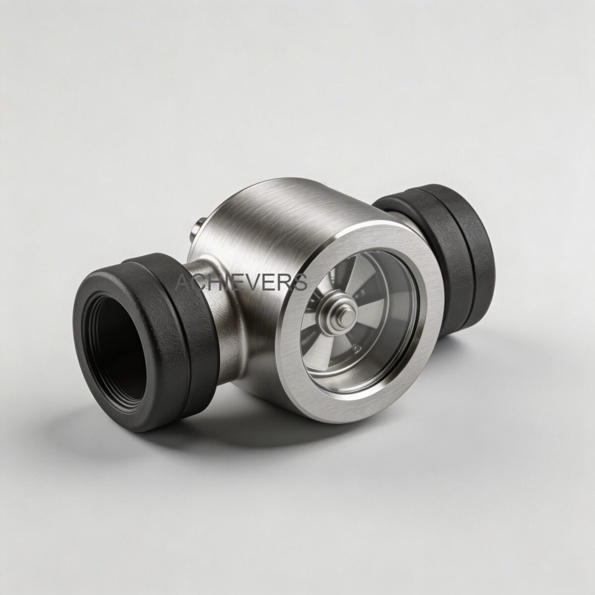
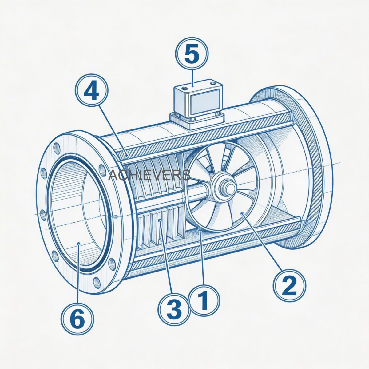
To effectively diagnose measurement anomalies, one must first understand the fundamental operating principles of the instrument. High-accuracy industrial Oil Flow Meters utilize positive displacement (PD) technology—specifically, an oval gear or volumetric rotary cylinder design.
In this design, the measuring chamber contains exceptionally few moving parts. Fluid entering the meter forces the internal gears or cylinders to rotate. Each rotation displaces a highly precise, known volume of fluid. Because the clearance between the rotors and the measuring chamber walls is machined to microscopic tolerances, fluid "slip" (unmeasured fluid bypassing the rotors) is minimized, making this technology essential for high-viscosity liquids.
The physical rotation is transmitted to a register via a high-efficiency magnetic coupling. This eliminates the need for dynamic mechanical seals, meaning only one moving part assembly is directly exposed to the metered fluid, ensuring leak-free operation and long-term reliability. Typically, standard accuracy is +/- 0.5% of reading, with high-precision models achieving +/- 0.2% and a repeatability of 0.02%.
Technology Comparison Table
No single flow measurement technology is ideal for every application. To aid in diagnostics and system design, engineers must understand how positive displacement compares to other dominant technologies.
| Parameter | Positive Displacement (PD) | Turbine Flow Meters | Coriolis Mass Meters | Electromagnetic Flow Meters |
| — | — | — | — | — |
| Measurement Principle | Volumetric (Rotary Cylinder / Oval Gear) | Velocity (Rotor RPM) | Mass (Tube Oscillation) | Velocity (Faraday's Law) |
| Viscosity Dependency | High viscosity improves accuracy (less slip) | High viscosity severely degrades accuracy | Immune to viscosity changes | Immune, but requires conductive fluid |
| Typical Accuracy | +/- 0.5% to +/- 0.2% | +/- 0.5% to +/- 1.0% | +/- 0.1% to +/- 0.2% | +/- 0.5% |
| Upstream Straight Pipe Req. | None (0D/0D) | High (10D to 20D) | None | Medium (5D to 10D) |
| Pressure Drop | Low (Suitable for gravity feed < 1" head) | Medium to High | High | Minimal (Full bore) |
| Ideal Application | Lubricants, diesel, furnace oil, draw-offs | Low-viscosity clean fuels, water | High-precision custody transfer | Water, slurries, conductive acids |
| Vulnerability | Particulate damage, air entrapment | Bearing wear, viscosity shifts | High capital cost, heavy vibrations | Useless for non-conductive oils |
"When to Use This Technology" Decision Matrix
- Use Positive Displacement Oil Flow Meters when: The fluid is non-conductive, highly viscous (heavy fuel oil, hydraulic fluids), straight pipe runs are impossible to achieve, and flow is driven by gravity (e.g., operating under 1" head of oil) or pump.
- Do not use when: The fluid contains high amounts of abrasive solids that cannot be filtered by a 100-mesh strainer, or when metering aqueous, conductive fluids where magnetic meters excel without pressure drop.
2. Troubleshooting Matrix
When encountering anomalies, identifying the symptom accurately prevents unnecessary dismantling. The following matrix details the most common faults found during industrial oil flow meter diagnostics for manufacturers and plant operators.
| Symptom | Likely Root Cause | Diagnosis Steps | Corrective Action |
| — | — | — | — |
| Erratic or fluctuating totalizer readings | Air entrapment / Two-phase flow | Inspect upstream piping for leaks or cavitating pumps. Check for missing air eliminators. | Install a mechanical air release valve upstream; tighten suction side flanges. |
| Zero flow reading despite fluid movement | Seized rotor / Broken magnetic coupling | Verify bypass valve position. Isolate meter and check for foreign debris locking rotors. | Clean measuring chamber. Flush lines and ensure a 100-mesh strainer is installed. |
| Continuous measurement drift (over-reading) | Air bubbles displacing liquid volume | Listen for spitting sounds at nozzles. Check fluid level in supply tanks (vortexing). | Increase tank levels to prevent vortexing; install air elimination equipment. |
| Measurement drift (under-reading) | High fluid slip due to low viscosity / temperature spike | Measure operating temperature. Calculate fluid kinematic viscosity at operating conditions. | Recalibrate meter at operating temperature, or use a technology better suited for low-viscosity. |
| High pressure drop across meter | Clogged internal strainer / High viscosity | Check differential pressure gauges across the strainer and meter assembly. | Remove and clean the 100-mesh strainer. Ensure fluid viscosity is within limits. |
| Electronic display blank (TF 200) | Power supply failure | Use a multimeter to check the 12 to 24 V DC power supply from the remote totalizer. | Restore power supply; check wiring for shorts or ground faults. |
| No pulse output to PLC (PG 1) | Faulty pulse generator or damaged 3-core cable | Measure pulse frequency at the output terminals using an oscilloscope or frequency counter. | Replace pulse generator module; verify wiring integrity. |
| 4-20 mA signal erratic | Ground loops / EMI interference | Check FI converter wiring. Ensure shielded cables are grounded at one end only. | Reroute signal cables away from variable frequency drives (VFDs) and high-voltage lines. |
| Leaking from meter body | Blown O-rings / Over-pressurization | Check system pressure against meter specifications. Inspect for water hammer effects. | Replace O-rings; install pressure relief valves if water hammer is detected. |
| Mechanical counter stuck | Worn register gears / Moisture ingress | Detach the register top (rotatable every 90 degrees) and manually check gear movement. | Replace mechanical register assembly; ensure environmental sealing is intact. |
3. Step-by-Step Field Diagnosis Procedure
When addressing oil flow meter erratic reading causes and fixes, guesswork is expensive. Follow this methodical field diagnostic procedure to isolate electrical, mechanical, and fluid dynamic issues.
Required Tools: True RMS Multimeter, differential pressure gauge, calibration proving container (certified volume), oscilloscope (for pulse verification), and standard hand tools.
- System Safing and Isolation: Before diagnosing, divert flow through the recommended bypass line. This ensures plant processes remain uninterrupted. Isolate the meter using upstream and downstream block valves.
- Visual and Environmental Inspection: Verify that the physical installation matches oil flow meters supplier specifications. Check for severe vibration sources nearby, extreme ambient temperatures, and external fluid leaks at flanged or screwed joints (DIN ND10 specifications).
- Filtration Assessment: Open the upstream strainer. Positive displacement meters require a minimum 100-mesh strainer. If the strainer is missing, torn, or clogged, particulate contamination has likely entered the measuring chamber, scoring the cylinder walls and causing fluid slip.
- Air Entrapment Verification: This is a critical step in oil flow meter air in line troubleshooting. Positive displacement meters measure volume, regardless of whether that volume is oil or air. If a pump is drawing in air through a failing suction-side seal, or if a tank is running low and vortexing, air passes through the meter, causing gross over-reporting. Install an air release framework if pumping from low-level storage.
- Rotor and Chamber Integrity Check: Depressurize the line and carefully open the meter body. Inspect the oval gears or rotary cylinders. They should rotate freely by hand. Any resistance indicates particulate jamming or thermal expansion binding.
- Magnetic Coupling Test: With the measuring chamber exposed and the register attached, rotate the gears manually. The mechanical counter or pulse generator should respond instantly. If not, the magnetic coupling has failed or sheared.
- Electrical Signal Verification (For Electronic Models): If using the PG 1 Pulse Generator and TF 200 Remote Totalizer:
- Verify the 12 to 24 V DC supply across the power terminals.
- Using a multimeter set to frequency (Hz), measure the output signal via the three-core cable while flow is occurring.
- Engineering Calibration Note: To verify pulse accuracy, utilize the standard scaling formula: Flow Rate (Liters/Minute) = [Pulse Frequency (Hz) * 60] / K-Factor (Pulses/Liter). If the calculated flow rate drastically deviates from the mechanical register, the PG 1 requires replacement or recalibration.
- 4-20 mA Loop Diagnosis: For systems utilizing the FI Combined Batching unit (BTF 200), measure the loop current. A reading of 0 mA indicates an open circuit; a reading below 4 mA indicates a sensor fault; and erratic jumping indicates electromagnetic interference (EMI) requiring better shielding.
4. Installation and Setup Errors That Cause Ongoing Problems
A majority of recurring field issues stem from the initial commissioning phase. An improperly installed meter will permanently suffer from oil flow meter pressure drop troubleshooting loops. Below are the most frequent installation errors and their immediate corrections.
| Installation Error | Resulting Symptom | Engineering Correction |
| — | — | — |
| Absence of a 100-mesh strainer | Rotors seize, flow stops, high pressure drop | Immediately install a mesh strainer upstream. Flush pipelines thoroughly before fitting. |
| No air eliminator on pumped lines | Artificial totalizer inflation, erratic reading | Install an air release framework before the meter to vent entrained gases. |
| Lack of a bypass manifold | Plant shutdown required for basic meter maintenance | Plumb a three-valve bypass system to allow servicing without stopping the process flow. |
| Incorrect line sizing | Excessive pressure drop or poor low-end resolution | Match meter to maximum flow rate, not just pipe size. Use reducers for small flows in large pipes (e.g., 15mm-25mm meters for low consumption). |
| Wrong dial orientation causing misreads | Parallax errors by operators logging totals manually | Remove the register top and rotate/secure it into one of the four cardinal positions for direct line-of-sight. |
| Gravity feed with excessive restriction | Zero flow, meter fails to turn under low head | Utilize larger 50mm or 80mm size meters specifically designed to operate under 1" head of oil without pumping. |
5. Preventive Maintenance to Avoid Recurrence
Routine maintenance is the only defense against the harsh realities of industrial fluid transfer. Heavy fuel oils, diesel with high sulfur content, and contaminated draw-offs from storage tanks will eventually degrade any precision instrument if left unchecked. Implementing a structured maintenance schedule drastically reduces the total cost of ownership.
Weekly:
- Visually inspect the meter body and flanges for weeping or seeping seals.
- Monitor the differential pressure across the upstream strainer. An increasing pressure drop is the first leading indicator of particulate buildup.
Monthly:
- Isolate the line via the bypass and physically remove the 100-mesh strainer. Wash it in a suitable solvent and blow it dry with compressed air.
- For electronic systems using the BTF 200 batching unit, verify the 4-20 mA signal output against the control room's DCS/PLC readings to ensure no signal degradation or ground loop interference has developed.
Bi-Annually / Annually:
- Conduct a volumetric proving test. Dispense fluid into a certified calibration prover. Compare the registered volume against the proven volume. Standard accuracy should remain consistent between calibration levels at better than +/- 0.5%. Use the stepless calibration framework to adjust if minor mechanical wear has induced slip.
- Inspect the pulse generator wiring harness for brittleness or exposure to corrosive industrial atmospheres.
6. When to Call Service vs. Fix Yourself
Knowing the limits of field maintenance prevents accidental destruction of highly calibrated components. The rugged volumetric rotary cylinder design allows for straightforward maintenance, but precision tolerances dictate strict boundaries.
Field-Fixable:
- Cleaning or replacing the integrated mesh strainer.
- Rotating the mechanical register for better viewing angles.
- Troubleshooting power supplies and pulse wiring to remote totalizers.
- Replacing external flanged O-rings and fixing pipe leaks.
- Purging air from the system and installing upstream air eliminators.
Requires Factory Service / Replacement:
- Rotor/Cylinder Scoring: If the measuring chamber walls or the rotary cylinders are deeply scratched by abrasive particles passing a failed strainer, the fluid slip will permanently ruin accuracy. These cannot be machined in the field; the measuring unit must be replaced.
- Magnetic Coupling Failure: If the magnetic link between the wet side and dry side is demagnetized or sheared due to extreme shock loading or over-pressurization.
- Circuit Board Failure: Internal failure of the FI converter or BTF 200 batching circuitry due to lightning strikes or high-voltage shorts.
FAQ
Q: Why does my flow meter read accurately at high flow rates but lose accuracy at low flows?
A: This is usually caused by fluid "slip" inside the measuring chamber. At very low flow rates, a higher percentage of the fluid leaks past the clearances between the rotor and the housing without turning the gears. This is exacerbated if the oil viscosity has dropped due to high temperatures.
Q: Is straight pipe required upstream of this technology?
A: No. Because positive displacement technology measures direct volume rather than velocity profiles, it is largely unaffected by outside components caused by installation. It does not require the 10-20 diameters of straight pipe that turbine or ultrasonic meters demand.
Q: What causes the pressure drop across the meter to suddenly spike?
A: A sudden spike is almost always due to a clogged upstream strainer. If the 100-mesh strainer becomes blinded by rust, sludge, or wax from heavy oils, flow is restricted. Additionally, a severe drop in ambient temperature can spike the fluid's viscosity, drastically increasing the pressure required to turn the mechanical gears.
Q: How do I integrate this mechanical meter into my plant's digital DCS?
A: While typically supplied with mechanical counters requiring no power, you can equip the meter with an optional Pulse Generator (PG 1) and an FI converter. This setup transforms the mechanical rotation into a pulse signal, which is then converted into a standard 4-20 mA output suitable for process controls and remote instrumentation.
Q: Can this meter handle gravity-fed offloading without a pump?
A: Yes. The low pressure drop inherent in the oval gear design makes it highly suitable for gravity applications. For emptying oils under a gravity head, 80mm or 50mm size meters are recommended, as they can operate effectively even under just a 1" head of oil.
Q: Are erratic readings normal when first commissioning the meter on a new pipeline?
A: No, but they are common if the pipeline wasn't properly flushed or if air wasn't purged. Emptying pipelines trap air, which the meter reads as volume. Ensure an air release system is used and the lines are fully bled before recording official totals.
Q: For global applications, including oil flow meters for generators in India troubleshooting, does extreme ambient heat affect accuracy?
A: High ambient heat affects the fluid, not directly the meter's electronics (within rated limits). Heat lowers the oil's kinematic viscosity. If the viscosity drops significantly, internal fluid slip increases, potentially causing the meter to slightly under-read. Recalibration at the operating temperature resolves this.
For advanced technical support, system sizing, or to replace failing units in your facility, contact our engineering team directly. Please provide the exact oil flow meters application, desired line size, maximum flow rate, operating temperature, and whether you require gravity feed or pumped specifications so we can engineer the optimal measurement solution for your plant.