
Industrial plants across India—from petrochemical complexes in Gujarat to pharmaceutical hubs in Baddi—rely heavily on liquid fuels. Whether feeding a 1500 kVA DG set during grid power fluctuations or running high-capacity boilers and thermopack heaters, accurate fuel monitoring is the baseline for operational efficiency. When high-value fluids like high-speed diesel (HSD), light diesel oil (LDO), and furnace oil are consumed in large volumes, even a 1% measurement error can translate to lakhs of rupees in unaccounted losses annually. Choosing the right Oil Flow Meters is the most critical instrumentation decision a plant manager can make to prevent inventory shrinkage, detect equipment inefficiencies early, and ensure precise receipt measurement from bulk tankers.
However, selecting instrumentation for Indian industrial environments requires looking beyond the basic datasheet. High ambient temperatures, particulate-contaminated fuels, monsoon humidity, fluctuating power quality, and gravity-fed piping configurations demand robust, purpose-built metering technologies. This highly detailed guide provides instrumentation engineers, plant managers, and procurement heads with a technical roadmap for sizing, selecting, and installing Oil Flow Meters to achieve unwavering accuracy and long-term reliability.
1. What Is Oil Flow Meters and What Does It Do
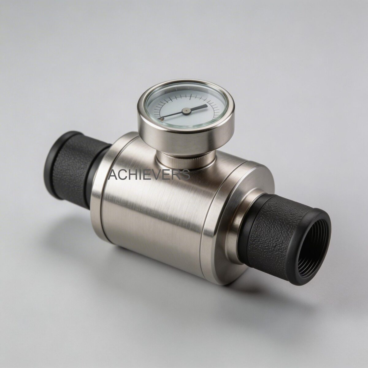
At its core, industrial Oil Flow Meters are precision volumetric measuring instruments designed to totalize and record the exact quantity of viscous hydrocarbons passing through a pipeline. The industry standard for these applications is the Positive Displacement (PD) type, specifically utilizing an oval gear or volumetric rotary cylinder design.
Unlike velocity-based meters that infer flow from the speed of the fluid, positive displacement meters divide the fluid into discrete, known volumes. The fluid pressure forces the internal gears or cylinders to rotate, and each rotation sweeps a highly precise volume of oil from the inlet to the outlet. Because parts in contact with the fluid are minimal and utilize highly efficient magnetic couplings between the measuring chamber and the register, only one moving part is exposed to the metered fluid. This drastically simplifies maintenance and extends the operational lifecycle.
Crucially, the volumetric rotary cylinder design ensures that measurement accuracy is maintained irrespective of the plane or angle in which the meter is mounted. For applications ranging from bulk storage tank draw-offs to point-of-use consumption tracking, this technology offers unmatched field-proven performance, especially for high-density and high-viscosity liquids.
Core Technical Specifications
Below is the standard engineering specification data for the Achievers brand meters manufactured by Lumen Instruments:
| Specification Parameter | Value / Rating | Engineering Notes |
| :— | :— | :— |
| Line Size Range | 6 mm to 150 mm (1/4" to 6") | Covers small burner feeds up to main storage draw-offs |
| Standard Accuracy | ± 0.5% of reading | Typical accuracy over the specified flow range |
| High-Precision Accuracy | ± 0.2% (Furnished on request) | Ideal for Legal Metrology / commercial receipt measurement |
| Repeatability | Better than 0.02% | Ensures consistent batching and consumption tracking |
| Pressure Drop ($\Delta$P) | Ultra-low (Operates under 1" head) | Capable of gravity unloading without supplemental pumping |
| Strainer Requirement | Minimum 100 mesh | Mandatory upstream to prevent rotor jamming from particulates |
| Mounting / Connections | Screwed (15-25mm), Flanged (40-80mm) | Flanges drilled to DIN ND10 specifications |
| Warranty | 1 Year + 2 Years Extended (on demand) | Assures long-term field reliability |
2. Key Selection Criteria for Indian Industrial Buyers
When deploying measurement instruments in Indian site conditions, a cut-and-paste approach to sizing will inevitably lead to failure. Instrumentation engineers must map the application parameters against the physical characteristics of the metering technology.
A. Fluid Viscosity and Temperature Profiling
Viscosity is the most critical parameter in selecting a positive displacement meter. While Oil Flow Meters thrive on high-viscosity fluids (which act as a natural sealant between the rotors and the measuring chamber walls, reducing "slip" and improving accuracy), temperature variations in India can drastically alter viscosity. Furnace oil that flows smoothly at 60°C in a pre-heated boiler line will turn into sludge during a winter night shutdown. Engineers must specify the meter based on the kinematic viscosity at the lowest operational temperature to prevent excessive pressure drops or mechanical shearing forces on the meter's gears.
B. Pressure Drop and Available Head
A common application in Indian plants is gravity unloading from bulk storage tanks. Many technologies fail here because they require significant line pressure to operate. The Achievers rotary cylinder design features an exceptionally low pressure drop, capable of operating effectively even under a mere 1-inch head of oil. If unloading via pumps, a 50mm or 80mm meter is ideal; if utilizing purely gravity head, 80mm is highly recommended to maximize flow rate without choking the line.
C. Contamination and Filtration Strategy
Indian fuel supply chains often introduce particulate contamination—dust, rust, and suspended solids—during transit. Because positive displacement meters operate with micro-clearances between the rotors and the chamber walls, hard particulates can cause catastrophic jamming. It is non-negotiable to install an upstream strainer of at least 100 mesh. Before final commissioning, pipelines must be thoroughly flushed to remove construction debris like welding slag.
D. Straight Pipe Run Requirements
One of the most significant advantages of PD technology over velocity meters (like turbine or vortex) is its immunity to flow profile distortions. Industrial boiler rooms and generator canopies in India are often cramped, leaving no room for the 10D/5D (10 pipe diameters upstream, 5 downstream) straight pipe runs required by other meters. Oil Flow Meters are not affected by outside elements caused by installation geometry, allowing them to be bolted directly after elbows or valves.
E. Output Signals and Automation Compatibility
Modern plant environments require integration with Building Management Systems (BMS), SCADA, or PLCs. While mechanical counters are perfect for remote areas lacking stable power, automated plants should utilize solid-state electronics. A Pulse Generator (PG 1) requires a 12-24V DC supply and converts mechanical motion into pulse signals via a three-core cable. For sophisticated process control, these pulses can be fed into an FI converter to generate standard 4-20 mA analog signals or utilized via RS-485 Modbus.
Technology Comparison Table
To understand why Positive Displacement is the preferred choice for hydrocarbons, consider this instrumentation comparison:
| Parameter | Positive Displacement (Oval/Rotary) | Positive Displacement Flow Meters (Gear) | Turbine Flow Meter | Vortex Flow Meter | Electromagnetic |
| :— | :— | :— | :— | :— | :— |
| Best Fluid Type | Diesel, Furnace Oil, LDO | Viscous resins, high-density oils | Low viscosity fluids, water | Steam, gases, very low viscosity | Conductive liquids (Water, Slurries) |
| Viscosity Limit | Excellent for high viscosity | Excellent for high viscosity | Poor (high viscosity causes drag) | Poor (viscosity dampens vortices) | N/A (Does not measure hydrocarbons) |
| Straight Pipe Requirement | None (0D Up / 0D Down) | None (0D Up / 0D Down) | High (10D Up / 5D Down) | Very High (15D Up / 5D Down) | Medium (5D Up / 3D Down) |
| Pressure Drop | Low (Works on gravity) | Moderate to High | High | Moderate | Zero |
| Accuracy Rating | ± 0.5% (up to 0.2%) | ± 0.5% | ± 1.0% | ± 1.5% | ± 0.5% |
'When to Use This Technology' Decision Matrix
- Use Positive Displacement: When measuring fuels (Diesel, Furnace Oil, LDO), when straight pipe runs are unavailable, when gravity head is the only driving force, and when extreme volumetric accuracy is required for consumption auditing.
- Use Turbine: When measuring clean, low-viscosity, non-lubricating fluids at high flow velocities where pressure drop is not a concern.
- Use Electromagnetic: When measuring conductive liquids like cooling water, effluent, or chemical dosing. (Note: Mag meters cannot measure non-conductive hydrocarbons like oil and diesel).

3. Model and Variant Comparison
Lumen Instruments manufactures several variants under the Achievers brand to suit different site requirements, ranging from basic mechanical totalization to advanced batch controlling.
| Model Variant | Flow Range / Size | Price Range (INR) | Output / Display Type | Best Application |
| :— | :— | :— | :— | :— |
| Achievers CE-118 | 15mm to 25mm | ₹9,999 – ₹19,499 | Mechanical Register | Small generator consumption monitoring, low-flow burner lines, remote off-grid sites. |
| Achievers CE-119 | 40mm to 80mm | ₹10,999 – ₹19,999 | Mechanical / Digital | Gravity unloading from bulk storage tanks, high-flow process heating lines. |
| Achievers CE-120 | 25mm to 150mm | ₹9,999 – ₹62,499 | Digital (Pulse / 4-20mA / RS-485) | Plant-wide SCADA integration, Liquid Batching Systems, commercial fuel receipt measurement. |
Engineering Note on Electronic Systems: For batch dispensing, the BTF 200 (Combined Batching, Totalizer, and Rate of Flow Unit) interfaces with the PG 1 pulse generator. It features two set points allowing automated dispensing of pre-determined quantities of liquids, closing solenoid valves exactly when the target volume is reached.
4. Common Mistakes Indian Buyers Make When Choosing
Procurement errors in instrumentation often manifest as operational headaches months after commissioning. Avoid these frequent engineering missteps:
- Sizing by Pipe Size Instead of Flow Rate:
- The Mistake: Ordering a 50mm meter simply because the pipeline is 50mm.
- The Consequence: If the actual flow rate is only 20 liters per minute, a 50mm meter will operate at the extreme bottom of its turndown ratio, resulting in massive accuracy degradation. Always size the meter based on the maximum and minimum operational flow rates. If the flow rate is small but the pipeline is large, reducers must be used (e.g., using a 15mm or 20mm meter with expansion flanges).
- Omitting Air Release Valves during Pump Unloading:
- The Mistake: Pumping from mobile tankers directly through the meter without an air eliminator.
- The Consequence: When tankers run empty, the pump introduces massive amounts of air into the line. A volumetric meter will measure this air as if it were expensive fuel, leading to artificial inventory inflation and false receipt records. An air release system is mandatory for pumped unloading.
- Ignoring the Bypass Line Requirement:
- The Mistake: Hard-piping the meter directly in-line without a bypass manifold.
- The Consequence: When the 100-mesh strainer inevitably clogs with debris, the entire process line must be shut down for maintenance. Always install the meter and its associated filter with a three-valve bypass manifold to simplify servicing without halting plant operations.
- Neglecting Viscosity Calibration Factors (Meter Slip):
- The Mistake: Assuming factory calibration holds true for all fluid types.
- The Consequence: A meter calibrated on light diesel will show slight deviations if used for thick furnace oil due to changes in fluid slippage.
- Calibration Note: Always establish a site-specific calibration factor using a master prover.
- Meter Factor (MF) = True Volume / Metered Volume
- Multiply subsequent readings by the MF to achieve ± 0.2% commercial accuracy.
- Failing to Rotate the Register for Readability:
- The Mistake: Installing the meter in a physically awkward position and forcing operators to climb or bend unsafely to read the totalizer.
- The Consequence: Operators misread the dials, leading to bad data in the logbooks. The register top of Achievers Oil Flow Meters can be easily removed and rotated in 90º increments to ensure the display is perfectly aligned for ergonomic visual reading at any angle.
5. Enquiry Specification Checklist
To ensure you receive the precise Oil Flow Meters for your application, provide the following engineering parameters to the manufacturer during the enquiry phase:
- Fluid Characteristics: Specify the exact oil type (HSD, LDO, Furnace Oil, Mineral Oil, Hydraulic Oil).
- Flow Rate Profile: Provide the Minimum, Normal, and Maximum flow rates (e.g., in Liters Per Hour or Liters Per Minute).
- Kinematic Viscosity: Provide the viscosity at standard ambient and actual operating temperatures (in cSt or SSU).
- Operating Pressure: Specify the normal operating pressure and the maximum allowable pressure drop across the meter. Note if the system is gravity-fed.
- Operating Temperature: Minimum and maximum fluid temperatures to ensure correct internal clearances and seal materials (Viton, PTFE, etc.).
- Line Size and End Connections: Specify pipe diameter and preferred connection type (Screwed BSP/NPT or Flanged DIN ND10/ANSI).
- Output Requirements: Specify if you need a direct mechanical display, Pulse output for remote totalization, 4-20mA for flow rate indication, or RS-485 for SCADA integration.
- Accessories: Confirm the inclusion of a 100-mesh strainer and, if applicable, an air release eliminator and BTF 200 batching controller.
FAQ
Q: Do I need straight pipe runs upstream and downstream of these flow meters?
A: No. Because they use a positive displacement rotary cylinder design, they do not require a fully developed velocity profile. You can install them directly after elbows, valves, or T-junctions without compromising the ± 0.5% accuracy.
Q: Can this meter operate without an external power supply?
A: Yes. The standard mechanical variants feature a robust gear-driven register that requires absolutely no electricity. This makes them ideal for remote generator monitoring or off-grid fuel depots.
Q: What happens if contaminated fuel enters the meter?
A: Hard particulates can score the measuring chamber or jam the precision rotors. It is strictly recommended to install a strainer of at least 100 mesh upstream of the meter to filter out particulate contamination.
Q: Will the meter cause a pressure bottleneck in my gravity-fed unloading line?
A: No, these meters are engineered for an exceptionally low pressure drop. They can effectively measure high-density fluids and operate even under a minimal 1-inch head of oil without requiring supplemental pumping.
Q: How do I integrate the meter readings into my plant's PLC system?
A: You can equip the meter with an optional PG 1 pulse generator. This unit converts mechanical motion into a pulse signal (requiring a 12-24V DC supply), which can be further converted into a 4-20mA signal or RS-485 Modbus output for seamless PLC/SCADA integration.
Q: Are these meters approved for Legal Metrology in India?
A: High-accuracy variants capable of ± 0.2% precision can be furnished on request. If you are using the meter for commercial custody transfer or exact receipt measurement, ensure you specify this requirement so the unit can be calibrated to comply with relevant weights and measures regulations.
Q: What sizes are best for generator consumption versus bulk storage tank draw-offs?
A: For monitoring oil consumption in DG sets and boilers, smaller 15mm, 20mm, or 25mm meters are ideal. For bulk unloading or tank draw-offs where flow rates are substantially higher, 40mm, 50mm, or 80mm flanged meters should be specified.
Ready to gain absolute control over your plant's fuel inventory and consumption? Contact our instrumentation engineering team today with your fluid type, flow rate profile, and site conditions, and we will help you select the perfectly sized Oil Flow Meters to eliminate measurement errors and safeguard your operational budget.