
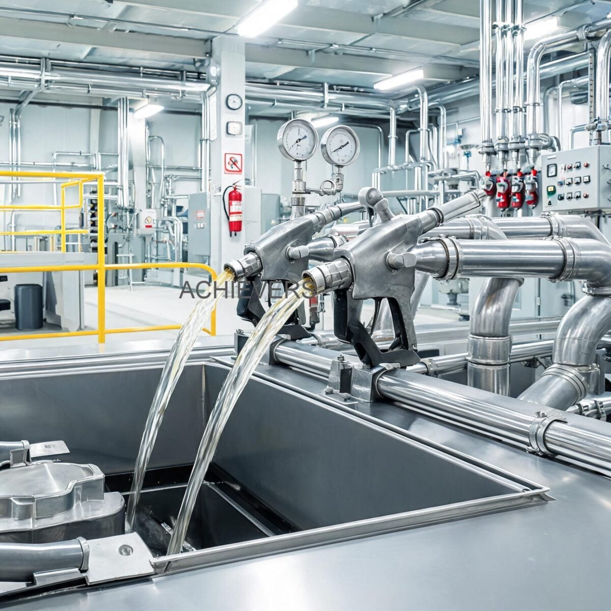
Selecting the right dispensing hardware for fluid transfer operations is a critical engineering decision that directly impacts facility safety, fluid accounting, and operational uptime. While upstream pumps and storage tanks often receive the bulk of procurement attention, the final control element—the dispensing nozzle—dictates the efficiency of the entire transfer loop. In high-volume industrial environments, choosing the wrong Fuel Nozzles leads to catastrophic fluid hammer effects, premature hose fatigue, fugitive emissions, and significant volumetric discrepancies during fuel reconciliation.
For instrumentation engineers and plant managers operating across global markets—from extreme high-temperature mining sites in the Middle East to sub-zero forestry operations in North America—dispensing hardware must comply with stringent international safety standards (such as ATEX for explosive atmospheres and ISO guidelines for fluid transfer). This buyer’s guide explores the engineering mechanics behind modern dispensing technology, breaking down flow limits, pressure ratings, auto-shutoff venturi dynamics, and fluid compatibility. By mapping these technical specifications to real-world industrial operating conditions, procurement teams can specify hardware that prevents dangerous leaks, eliminates unsafe fills, and drastically reduces unscheduled maintenance downtime.
1. What Is a Fuel Nozzle and What Does It Do
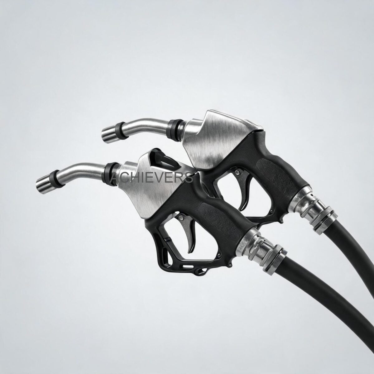
In fluid dynamics and industrial dispensing, a fuel nozzle acts as a specialized mechanical valve designed to control the directional flow, velocity, and shutoff parameters of volatile liquids entering a receptacle. Far from being a simple open/close valve, modern Fuel Nozzles integrate sophisticated flow measurement technologies and hydrodynamic auto-shutoff mechanisms to ensure safe operation. When dispensing diesel, gasoline, or motor oil, the nozzle must balance flow velocity against the physical limitations of the receiving tank's venting capacity to prevent hazardous splash-back.
Based on strict manufacturing standards and precision engineering, the Fuel Nozzles utilized in industrial environments feature rugged construction and tightly toleranced flow paths. The integration of swivel pipe inlets prevents hose kinking under high pressure, while built-in digital or mechanical flow meters allow for highly accurate batching directly at the point of use.
Below are the primary technical specifications for standard industrial variants based on rigorous quality testing:
| Specification Parameter | Value | Engineering Notes |
| Inlet Thread Size | BSP 3/4 inch (Digital: 1 inch) | British Standard Pipe thread ensures high-pressure sealing; requires compatible swivel joints. |
| Spout Diameter | 13/16 inch | Optimized for standard diesel and gasoline vehicle/equipment receptacles. |
| Flow Rate Range | 0 – 60 L/min | Supports both low-flow precision top-offs and high-speed bulk transfer. |
| Maximum Operating Pressure | 0.18 MPa (1.8 Bar) | Engineered for standard transfer pump architectures; prevents seal blowout. |
| Net Weight | 1.14 kgs/pc | Ergonomically balanced to reduce operator fatigue during continuous batching. |
| Insulator Construction | Heavy-duty Red Polymer | Provides impact resistance and thermal insulation during extreme temperature dispensing. |
2. Key Selection Criteria for Global Industrial Buyers
Selecting the appropriate dispensing hardware requires matching the physical properties of the fluid and the dynamics of the pumping system to the nozzle's capabilities. Instrumentation engineers must evaluate the following parameters when specifying equipment for harsh industrial environments:
Flow Rate and Velocity Limits
Dispensing fluids at excessive velocities causes turbulence, foaming, and static electricity buildup—a severe hazard in ATEX-rated zones. The optimal flow rate of 0 to 60 L/min ensures that diesel and motor oil (which have higher viscosities than gasoline) can be transferred rapidly without exceeding the standard 0.18 MPa pressure threshold. Operating beyond 60 L/min with a 13/16 inch spout increases the fluid velocity exponentially, risking cavitation and premature wear on the valve seat.
Pressure Drop and System Head
Every nozzle introduces a pressure drop into the system. With a maximum rated pressure of 0.18 MPa, the nozzle must be matched with transfer pumps that operate within this differential. High-head hydraulic pumps will overpower the nozzle's internal spring mechanisms, leading to continuous leaks. Conversely, if the upstream pressure is too low, the auto-shutoff venturi mechanism will fail to generate the required vacuum to trip the safety latch.
The Auto-Shutoff Mechanism (Venturi Effect)
Automatic shutoff is non-negotiable in global industrial standards to prevent environmental spills. This mechanism relies on fluid flow drawing air through a small sensing port at the tip of the spout via the Venturi effect. When fluid covers this port, the vacuum spikes, triggering a diaphragm that releases the hold-open latch. Buyers must ensure the nozzle is rated for the specific fluid's specific gravity, as highly viscous motor oils can prematurely block the sensing port in improperly specified nozzles.
Material Compatibility and Wetted Parts
Industrial sites process highly corrosive and varying grades of hydrocarbons. Internal O-rings, valve poppets, and main body castings must be chemically compatible with the fluid. A nozzle designed for diesel might utilize nitrile rubber seals, whereas transferring aggressive solvent-laced fuels may require Viton or PTFE seals to prevent degradation and catastrophic valve failure.
Thread Standards and Swivel Coupling Interfaces
A frequent point of failure in dispensing operations is the connection between the delivery hose and the nozzle inlet. Specifying the correct BSP (British Standard Pipe) thread—typically 3/4" for standard flows and 1" for digital metering nozzles—is vital. Furthermore, utilizing swivel pipe inlets is mandatory in heavy industrial applications to relieve torsional stress on the hose, extending its operational life and preventing catastrophic ruptures during handling.
Ergonomics for Continuous Operation
In heavy fleet refueling or continuous batching operations, physical fatigue leads to unsafe handling practices. A precise net weight of 1.14 kg strikes the exact engineering balance between necessary structural integrity (sturdy construction to survive drops onto concrete) and ease of manipulation.
3. Technology Comparison Table: Nozzle Variants
No single dispensing technology fits every application. Engineers must choose between mechanical auto-shutoff designs and integrated digital metering solutions based on whether the primary goal is rapid transfer or precise volumetric accounting. When integration with larger facility automation is required, buyers might also explore upstream Positive Displacement Flow Meters combined with standard dispensing ends.
| Parameter | Mechanical Auto-Shutoff Nozzle | Digital Metering Nozzle | High-Flow Manual Nozzle |
| Actuation Mechanism | Mechanical trigger with Venturi trip | Mechanical trigger with Venturi trip | Manual trigger (operator controlled) |
| Flow Measurement | None (Requires upstream flow meter) | Integrated electronic turbine/gear | None |
| Typical Inlet Size | BSP 3/4 inch | BSP 1 inch | BSP 1 inch or larger |
| Flow Rate Capability | 0 – 60 L/min | 0 – 60 L/min | 0 – 120+ L/min |
| Pressure Rating | 0.18 MPa | 0.18 MPa | Up to 0.35 MPa |
| Power Requirement | None | Battery (Lithium, intrinsically safe) | None |
| Best Application | Fleet fueling, heavy equipment top-offs | Precise batching, fluid accounting, oil | Emergency transfer, bulk tank filling |
| Maintenance Complexity | Low (periodic seal check) | Medium (calibration, battery change) | Very Low |
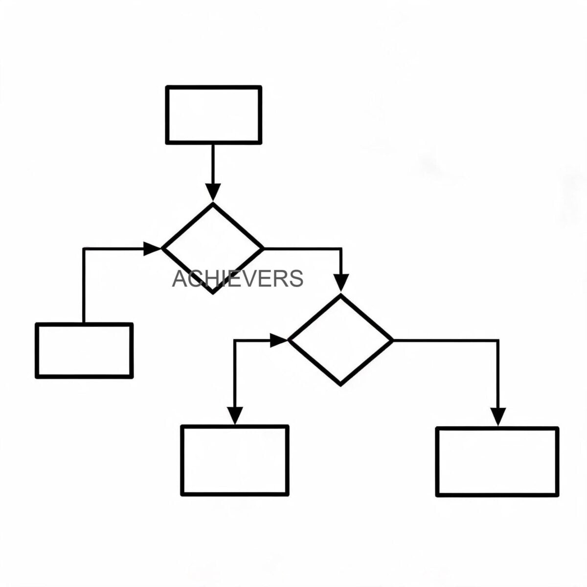
4. When to Use This Technology: Decision Matrix
To streamline procurement and engineering design, utilize this decision matrix to determine exactly which nozzle architecture best fits your specific operational parameters:
- Use Integrated Digital Metering Nozzles When:
- Dispensing expensive fluids (like synthetic motor oil) where point-of-use volumetric accounting is required.
- Upstream Diesel Flow Meters cannot be installed due to space constraints or mobile cart requirements.
- Operators need dual-measurement visibility directly in their hands to prevent over-batching into specific generator day tanks.
- Use Mechanical Automatic Shutoff Nozzles When:
- Operating in highly explosive environments where electronic components (even intrinsically safe ones) are discouraged.
- Refueling large fleets of diesel machinery where the operator must lock the trigger and monitor other equipment simultaneously.
- Capital expenditure must be minimized while still complying with environmental spill-prevention mandates.
- Use Manual High-Flow Nozzles (No Auto-Shutoff) When:
- Transferring fluid into open vats or highly irregular receptacles where a venturi sensing port would constantly falsely trip.
- Operating in sub-zero freezing conditions where ice accumulation frequently blocks standard venturi sensing ports.
5. Engineering Principles: Venturi Dynamics and Fluid Formulas
Understanding the mechanical behavior of automatic shutoff technology requires a brief look into fluid dynamics. The nozzle's safety mechanism relies entirely on Bernoulli's principle and the conservation of mass.
When the operator pulls the lever, the main valve opens, allowing fluid to flow past a venturi ring. According to the continuity equation, as the flow area decreases within the venturi, fluid velocity must increase.
Velocity (V) = Volumetric Flow Rate (Q) / Cross-Sectional Area (A)
As velocity increases, the dynamic pressure rises and the static pressure drops (Bernoulli's principle):
P_static + 0.5 * Density * V^2 = Constant
This localized drop in static pressure creates a vacuum. The nozzle is constructed with a small sensing tube running from this venturi down to the tip of the spout. While dispensing into an empty tank, this vacuum draws in ambient air through the spout tip, balancing the internal pressures.
However, the moment the fluid level in the tank rises and submerges the 13/16 inch spout tip, air can no longer be drawn in. The vacuum inside the nozzle housing instantly spikes. This sudden negative pressure differential pulls a flexible diaphragm backward. The diaphragm's movement displaces a set of locking rollers or a latch pin, causing the trigger linkage to instantly collapse. The heavy main spring then slams the main valve shut, terminating the flow in milliseconds and preventing an overflow.
Calibration Note for Engineers: The speed of this mechanical trip is highly dependent on fluid viscosity and pump flow rate. If a pump operates significantly below the optimal 60 L/min range (e.g., at 10 L/min), the venturi vacuum may not be strong enough to trip the diaphragm reliably when the spout is submerged. Always match the nozzle's design parameters to the pump's output curve.
6. Common Mistakes Industrial Buyers Make When Choosing
Procuring dispensing equipment without consulting fluid mechanics and site-specific operating conditions leads to continuous maintenance headaches. Here are the most critical mistakes buyers must avoid:
- Mismatching Flow Rates with System Pressure:
- Ignoring the Swivel Joint Requirement:
- Disregarding Fluid Viscosity and Temperature:
- Mixing Up Thread Standards (BSP vs. NPT):
- Neglecting Upstream Filtration:
- Overlooking Drop Resilience:
Purchasing a nozzle rated for 0.18 MPa and attaching it to a high-pressure transfer system causes violent fluid hammer when the auto-shutoff trips. The sudden deceleration of fluid creates a shockwave that can rupture upstream hoses and damage pump impellers.
Directly threading a heavy industrial hose into the BSP 3/4" or 1" inlet without a multi-plane swivel joint is a critical error. As the operator moves the nozzle, the torsional stress transfers directly to the hose crimp, leading to inevitable fatigue and hazardous fluid leaks.
Using a standard diesel nozzle to pump heavy motor oil in cold climates often results in nuisance tripping. As viscosity increases at low temperatures, the internal friction within the sensing tube changes, tricking the diaphragm into shutting off the flow prematurely.
Forcing an NPT (National Pipe Thread) fitting into a BSP (British Standard Pipe) thread will permanently cross-thread the aluminum body. While they may appear to fit initially, the difference in thread pitch and angle guarantees a high-pressure leak under operational load.
The internal tolerances of a digital metering nozzle and the auto-shutoff venturi are incredibly tight. Pumping contaminated diesel without upstream 10-micron filtration will clog the sensing port and jam the turbine blades, rendering both the safety shutoff and the metering useless.
Failing to specify heavy-duty insulator colors (like the impact-resistant red polymer) means the aluminum body bears the brunt of every drop onto a concrete pad, eventually warping the spout and destroying the seal geometry.
7. Enquiry Specification Checklist
To ensure your supplier delivers the exact configuration required for your industrial application, provide a comprehensive engineering specification. When submitting an enquiry, always detail the following steps and parameters:
- Specify Fluid Type: Clearly state whether the application is for diesel, gasoline, motor oil, or a combination. This determines the internal O-ring elastomer material (e.g., Nitrile vs. Viton).
- Define Required Flow Rate: State your normal operating volumetric flow (e.g., 45 L/min). Ensure it falls within the nozzle's optimal 0-60 L/min rating.
- State Maximum Operating Pressure: Provide the maximum deadhead pressure of your transfer pump to ensure it does not exceed the 0.18 MPa rating of the nozzle.
- Select Thread Interface: Explicitly specify the required inlet thread. Standard mechanical nozzles utilize BSP 3/4", while digital variants typically require a 1" inlet.
- Choose Auto-Shutoff vs. Manual: Define if the venturi-based automatic shutoff mechanism is mandatory for site safety compliance.
- Determine Metering Needs: Indicate if you require a Digital Flow Meter Metering nozzle with dual-measurement capability for precise batching.
- Specify Spout Dimension: Confirm that the standard 13/16" spout diameter is compatible with your machinery's receiving ports.
- Request Swivel Couplings: Always mandate that the quotation includes compatible swivel pipe inlets to eliminate hose torsion.
- Detail Operating Environment: Mention if the nozzle will be subjected to extreme ambient temperatures, corrosive salt-spray, or abrasive dust, ensuring the red polymer insulator and structural finish can withstand the conditions.
FAQ
Q: Can I use a nozzle rated for diesel to dispense highly viscous gear oils?
A: It is generally not recommended unless verified by the manufacturer. High-viscosity fluids can clog the narrow venturi sensing port designed for diesel, causing the automatic shutoff mechanism to either fail completely or trip prematurely due to flow resistance.
Q: What causes an automatic shutoff nozzle to constantly click off while dispensing?
A: Premature tripping is usually caused by dispensing at a velocity that is too high for the receiving tank's vent pipe, causing splash-back that covers the sensing port. It can also occur if the venturi tube is partially clogged with debris or if the flow rate exceeds the nozzle's 60 L/min design limit.
Q: Why is there a difference in inlet size between mechanical and digital nozzles?
A: Digital metering nozzles often feature a 1-inch inlet to accommodate the internal measurement mechanism (such as a turbine or oval gear) without introducing an excessive pressure drop, whereas standard mechanical nozzles efficiently operate with a BSP 3/4-inch inlet.
Q: How do I calibrate a digital metering nozzle?
A: Calibration involves dispensing a precise, known volume of fluid (e.g., into a certified proving can) and comparing it to the digital display. The user then accesses the nozzle's electronic menu to adjust the calibration factor (K-factor) to align the digital readout with the true dispensed volume.
Q: Is 0.18 MPa enough pressure for industrial fluid transfer?
A: Yes, 0.18 MPa (1.8 bar or roughly 26 PSI) is an optimized, safe operating pressure for light-to-medium industrial fluid transfer. It provides sufficient force to achieve 60 L/min flow rates without risking dangerous fluid hammer or bursting standard delivery hoses.
Q: What maintenance is required to ensure the auto-shutoff mechanism remains reliable?
A: Maintenance is minimal but critical. Operators should regularly inspect the 13/16 inch spout to ensure the small vacuum sensing port is completely clear of mud, ice, or waxy fuel buildup. Additionally, checking the inlet swivel for smooth rotation prevents hose-induced torque damage.
Q: Do these nozzles require a specific type of pump?
A: While they do not require a specific brand, they must be paired with pumps that operate within the 0 to 60 L/min flow range and do not exceed 0.18 MPa. Positive displacement rotary vane pumps or centrifugal transfer pumps with internal bypass valves are standard pairings.
To upgrade your facility's fluid transfer operations, reduce fugitive emissions, and improve batching accuracy, contact our engineering team today with your specific requirements. Please provide your targeted flow rate, fluid type, maximum pump pressure, and any specific digital metering or thread interface requirements so we can quote the exact dispensing hardware engineered for your harsh operating environment.