
The financial impact of an unplanned flow measurement failure in a continuous process facility extends far beyond the cost of replacing the instrument. For utilities like saturated steam, compressed air, and thermal oils, degraded accuracy quietly bleeds plant efficiency, resulting in fuel waste and compromised mass balances. While Vortex Flow Meters are celebrated for their absence of moving parts and rugged reliability, they are not entirely maintenance-free. Process scaling, pipeline vibration, sensor fatigue, and gasket degradation can severely impact the piezoelectric sensor’s ability to detect vortices accurately.
This comprehensive engineering guide details the rigorous preventive maintenance, inspection, and verification protocols required to sustain the accuracy and uptime of these critical flow measurement devices. By implementing a proactive diagnostic and cleaning schedule, instrumentation engineers can prevent premature component failure, ensure compliance with international measurement standards (ISO, API), and maintain the integrity of their facility’s energy monitoring infrastructure.
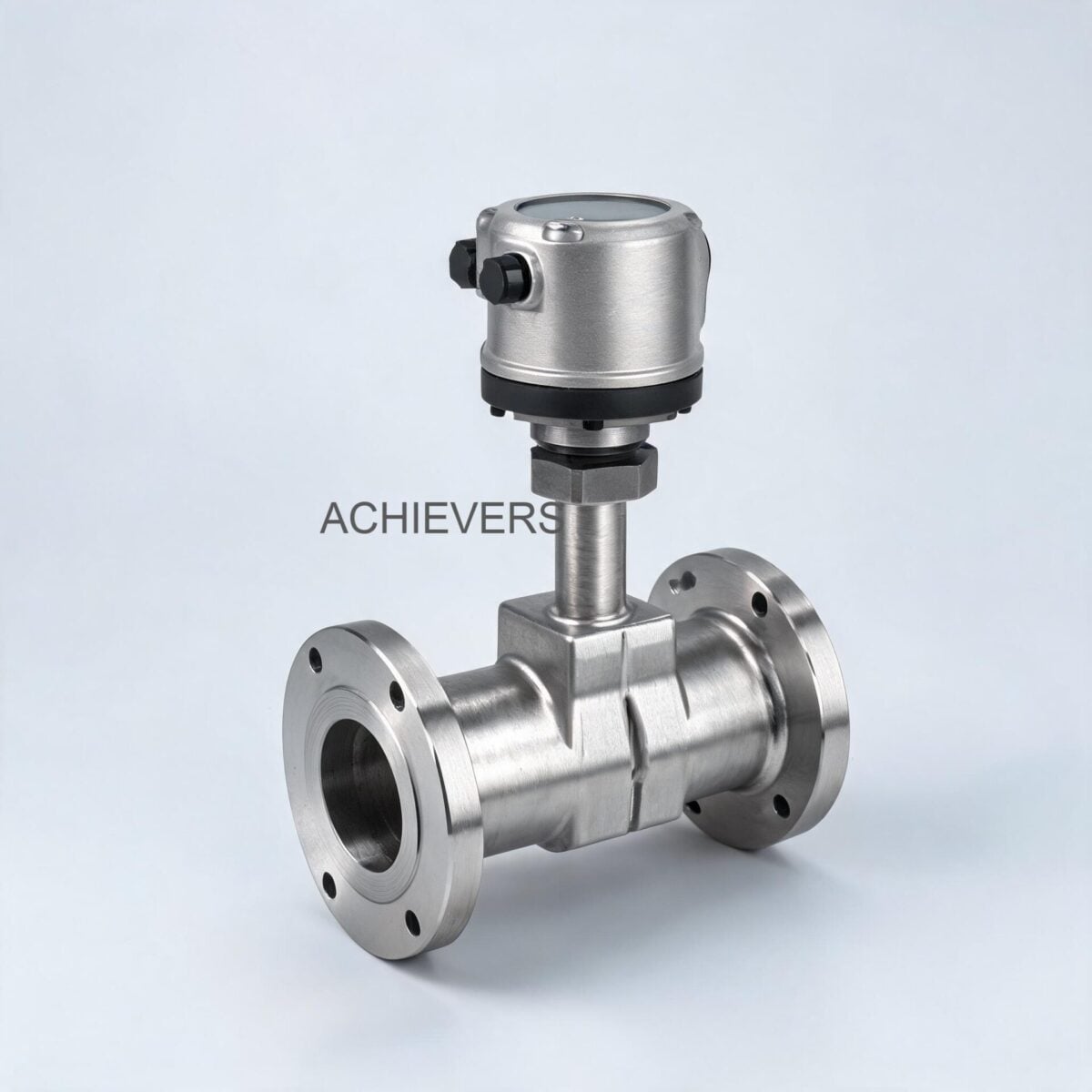
1. Product Overview and Critical Wear Components
To properly maintain Vortex Flow Meters, maintenance personnel must first understand the underlying physics of the Von Kármán effect. As fluid passes a strategically placed obstruction (the bluff body) inside the flow tube, alternating low-pressure zones—or vortices—are created. The frequency of these shedding vortices is directly proportional to the fluid velocity.
The governing engineering relationship is defined by the Strouhal formula:
f = (St x V) / d
Where f is the shedding frequency, St is the Strouhal number (dimensionless), V is the fluid velocity, and d is the width of the bluff body. Because the Strouhal number remains relatively constant across a wide range of Reynolds numbers (typically Re > 20,000), the meter provides exceptional linearity.
Based on industry-standard engineering configurations, high-quality Vortex Flow Meters possess several critical specifications that dictate their maintenance limits:
- Line Size: DN 15 to DN 300mm
- Operating Temperature: -50°C to 350°C
- Maximum Pressure: 20 kg/cm2
- Outputs: 4-20 mA, Pulses, RS 485 Modbus
- Advanced Features: Built-in pressure and temperature compensation for mass flow calculation
- Power Supply: 24Vdc two-wire loop powered
- Mounting Styles: Flange type, Sandwich (Wafer) type, and Clamp-On
While there are no rotating gears or bearings to wear out, several stationary components are subjected to immense physical and thermal stress. The primary wear components include the piezoelectric sensor assembly, the bluff body (which can suffer from erosion or scaling), the process seals/gaskets, the multivariable compensation sensors (RTD and pressure transducer), and the transmitter electronics exposed to ambient extremes.
Technology Comparison Table
No single flow measurement technology solves every application. Understanding how vortex shedding compares to other principles is crucial for both specification and diagnostic troubleshooting.
| Parameter | Vortex Flow Meters | Electromagnetic Flow Meters | Turbine Flow Meters |
| — | — | — | — |
| Measurement Principle | Von Kármán vortex shedding | Faraday’s Law of Induction | Mechanical rotor revolution |
| Compatible Fluids | Liquids, Gases, Steam | Conductive Liquids only (>5 µS/cm) | Clean Liquids and Gases |
| Moving Parts | None | None | Yes (Rotor and Bearings) |
| Pressure Drop | Moderate (due to bluff body) | Zero (unobstructed bore) | Moderate to High |
| Max Temperature Rating | High (Up to 350°C) | Moderate (Up to 150°C with PTFE) | Moderate (Up to 150°C) |
| Maintenance Priority | Sensor scaling, vibration checks | Electrode coating, liner wear | Bearing wear, rotor damage |
| Inbuilt Compensation | Yes (Pressure/Temperature) | Not applicable | External usually required |
"When to Use This Technology" Decision Matrix
Selecting the right maintenance approach requires confirming the meter is correctly applied in the first place. Use this matrix to validate your installation:
- Choose Vortex IF: You are measuring saturated or superheated steam, utility gases (compressed air, nitrogen), or high-temperature heat transfer fluids. The application has steady flow above the minimum Reynolds number (>20,000), and piping vibration is minimal or mechanically isolated.
- Choose Electromagnetic IF: You are measuring highly corrosive chemical slurries, municipal wastewater, or abrasive raw water where the fluid is conductive, and absolutely zero pressure drop is required.
- Choose Turbine IF: You are measuring ultra-clean, low-viscosity fuels or liquid hydrocarbons requiring extreme accuracy and high-frequency pulse outputs for batching, and steady lubrication of internal bearings is guaranteed.
2. Preventive Maintenance Schedule
A rigorous, documented preventive maintenance schedule protects the initial capital investment and prevents sudden measurement failure. Due to the high temperatures (up to 350°C) and pressures (20 kg/cm2) these meters endure, visual inspections and electronic verifications should be standardized into plant maintenance turnarounds.
| Task | Frequency | Responsible | Est. Time | Notes |
| — | — | — | — | — |
| Visual External Inspection | Monthly | Operator / Tech | 15 mins | Check for casing damage, paint peeling, or signs of external moisture ingress. |
| Flange Leak Detection | Monthly | Maintenance | 20 mins | Inspect flange and sandwich (wafer) mountings for microscopic weeping or steam leaks. |
| Zero Flow Signal Verification | Quarterly | I&E Tech | 30 mins | Verify output is exactly 4.00 mA with full pipe but zero fluid velocity. |
| Transmitter Housing Seal Check | Bi-Annually | I&E Tech | 15 mins | Inspect O-rings on the transmitter cover; replace if hardened or cracked. |
| Terminal Block Inspection | Bi-Annually | I&E Tech | 20 mins | Check 24Vdc two-wire connections for oxidation, corrosion, or loose terminals. |
| Low-Flow Cutoff Tuning | Annually | I&E Engineer | 45 mins | Adjust noise filtering to reject background pipeline vibration preventing false counts. |
| Multivariable Sensor Calibration | Annually | I&E Tech | 60 mins | Verify inbuilt pressure and temperature compensation sensors against certified references. |
| Bluff Body / Sensor Cleaning | Annually | Mechanical Team | 120 mins | Remove from line; chemically clean scaling from the shedding bar and sensor fins. |
| Process Gasket Replacement | Every 2-3 Years | Mechanical Team | 90 mins | Replace process seals during plant turnaround to prevent high-pressure blowouts. |
| Total Loop Verification | Every 2 Years | I&E Engineer | 60 mins | Inject frequency to simulate flow; verify entire loop through to DCS/SCADA via Modbus/4-20mA. |
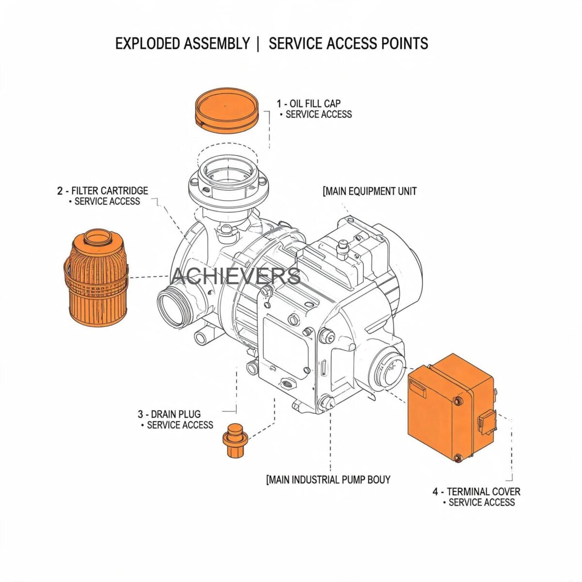
3. Step-by-Step Procedures for Key Tasks
Proper execution of maintenance tasks ensures human safety and instrumentation integrity. Standard Operating Procedures (SOPs) must be strictly followed, particularly in hazardous areas or high-pressure steam environments.
Procedure 1: Piezoelectric Sensor Inspection and Cleaning
Over time, scaling from hard water, boiler carryover, or particulate-laden gases can alter the bluff body's geometry, shifting the Strouhal number and degrading accuracy.
- Isolate the Pipeline: Coordinate with plant operations to secure the line. Apply standard Lock-Out/Tag-Out (LOTO) protocols to upstream and downstream isolation valves.
- Depressurize and Drain: Safely bleed off all internal pressure (up to 20 kg/cm2) using designated blowdown valves. Allow the meter body to cool if the process temperature was near its 350°C maximum.
- Disconnect Power: Remove the 24Vdc loop power at the control cabinet before opening the transmitter housing to prevent arc flashes in potentially explosive atmospheres.
- Remove Transmitter Connections: Open the enclosure, carefully disconnect the fragile sensor wiring harness from the main amplifier board, and document terminal positions.
- Extract the Sensor Assembly: For models designed with removable sensor cartridges, unbolt the sensor retaining flange. Carefully pull the piezoelectric assembly straight out without twisting, protecting the internal fins.
- Chemical Cleaning: Inspect the bluff body and sensor for calcium buildup or rust. Submerge the affected area in a mild, manufacturer-approved descaling solvent. Do not use abrasive files, wire brushes, or grinders, as altering the bluff body width (dimension d) permanently destroys the meter's calibration.
- Rinse and Dry: Thoroughly rinse the assembly with deionized water and dry completely using instrument-grade compressed air.
- Reinstallation: Install a new, OEM-specified, high-temperature torque gasket. Seat the sensor assembly, torque the retaining bolts in a crisscross pattern to the specified Nm rating, and reconnect the wiring harness.
Procedure 2: Calibration Verification and Loop Testing
Because the Strouhal number is governed by rigid geometry, vortex meters rarely suffer from traditional calibration "drift." However, the electronic amplifier, low-flow cutoff settings, and RS-485/4-20mA output stages require periodic verification.
- Connect Diagnostic Equipment: Attach a HART communicator or Modbus diagnostic tool to the transmitter terminals, alongside a high-precision digital multimeter (DMM) in series with the 4-20mA loop.
- Verify Process Conditions: Ensure the pipeline is full of fluid but completely static (zero flow).
- Zero Calibration Check: Read the DMM. The output must perfectly register 4.00 mA. If background pipeline noise (vibration from nearby pumps) is causing a false flow reading above 4mA, proceed to step 4.
- Adjust Noise Filtering: Access the transmitter menu and incrementally increase the low-flow cutoff limit or the vibration immunity filter until the zero-flow reading stabilizes at 4.00 mA.
- Simulate Full Scale: Use the diagnostic tool to digitally force the transmitter output to 100% of its programmed range. Verify the DMM registers exactly 20.00 mA and the DCS/SCADA system correctly registers the maximum flow rate.
- Verify Inbuilt Compensation: For mass flow applications, read the internal pressure and temperature values from the transmitter display. Compare these values against locally installed, calibrated test gauges and RTDs. Recalibrate the multivariable sensors if deviations exceed 0.5%.
- Frequency Injection (Optional): Disconnect the piezoelectric sensor and connect a frequency generator to the amplifier board. Inject a pulse rate corresponding to 50% flow capacity. Verify the volumetric calculation aligns with the theoretical mathematical constant.
- Document and Restore: Record all as-found and as-left parameters on a standardized ISO maintenance sheet. Remove test equipment, secure the housing cover tightly to ensure ingress protection, and return the loop to normal operation.
4. On-Site Spare Parts to Stock
Supply chain disruptions and logistics delays can transform a minor component failure into days of plant downtime. Maintaining a strategic inventory of consumable and wear parts is an inexpensive insurance policy against production losses.
| Part Description | Part Type | Recommended Qty | When to Replace |
| — | — | — | — |
| Process Flange Gaskets | Consumable | 4 per meter size | Every time the meter is removed from the pipeline. |
| Sensor Housing O-Rings | Consumable | 2 sets per meter | Bi-annually or if moisture ingress is detected. |
| Piezoelectric Sensor Assembly | Critical Spare | 1 per identical model | If flow signal is lost despite functioning electronics. |
| Main Amplifier PCBA | Critical Spare | 1 per 5 meters | If 4-20mA output fails, RS485 communication drops, or power surges occur. |
| Terminal Block / Barrier | Component | 2 units | If threads strip or heavy oxidation creates loop resistance. |
| Inbuilt RTD Probe | Spare | 1 unit | If mass flow calculations show persistent temperature deviations. |
5. Diagnosing Maintenance-Related Failures
Even with rigorous maintenance, extreme process environments can induce hardware anomalies. Troubleshooting requires systematically isolating whether the failure originates from the fluid mechanics, the pipeline environment, or the internal electronics.
| Failure Symptom | Missed Maintenance Task | Root Cause / Corrective Action |
| — | — | — |
| Constant low flow reading when valves are shut | Low-Flow Cutoff Tuning | Action: Pipe vibration is mimicking vortex shedding. Increase low-flow cutoff or install rigid pipe supports upstream and downstream. |
| Zero flow indicated during active process flow | Terminal/Wiring Inspection | Action: Check for severed piezoelectric wiring or a failed amplifier board. Replace PCBA if sensor resistance is out of spec. |
| Erratic or jumping flow rate output | Bluff Body Cleaning | Action: Severe scaling is causing non-uniform vortex shedding. Isolate, remove, and chemically clean the internal bluff body. |
| Mass flow output is wildly inaccurate | Multivariable Sensor Calibration | Action: The internal temperature (-50 to 350°C) or pressure (up to 20 kg/cm2) sensor has drifted. Recalibrate multivariable inputs. |
| Process fluid leaking at meter body | Gasket Replacement | Action: Thermal cycling has caused flange gasket failure. Replace seals and re-torque bolts to OEM specifications. |
| No RS 485 Modbus communication | Enclosure Seal Check | Action: Moisture ingress caused short-circuiting on the comms board. Replace O-rings, apply desiccant, and replace the board. |
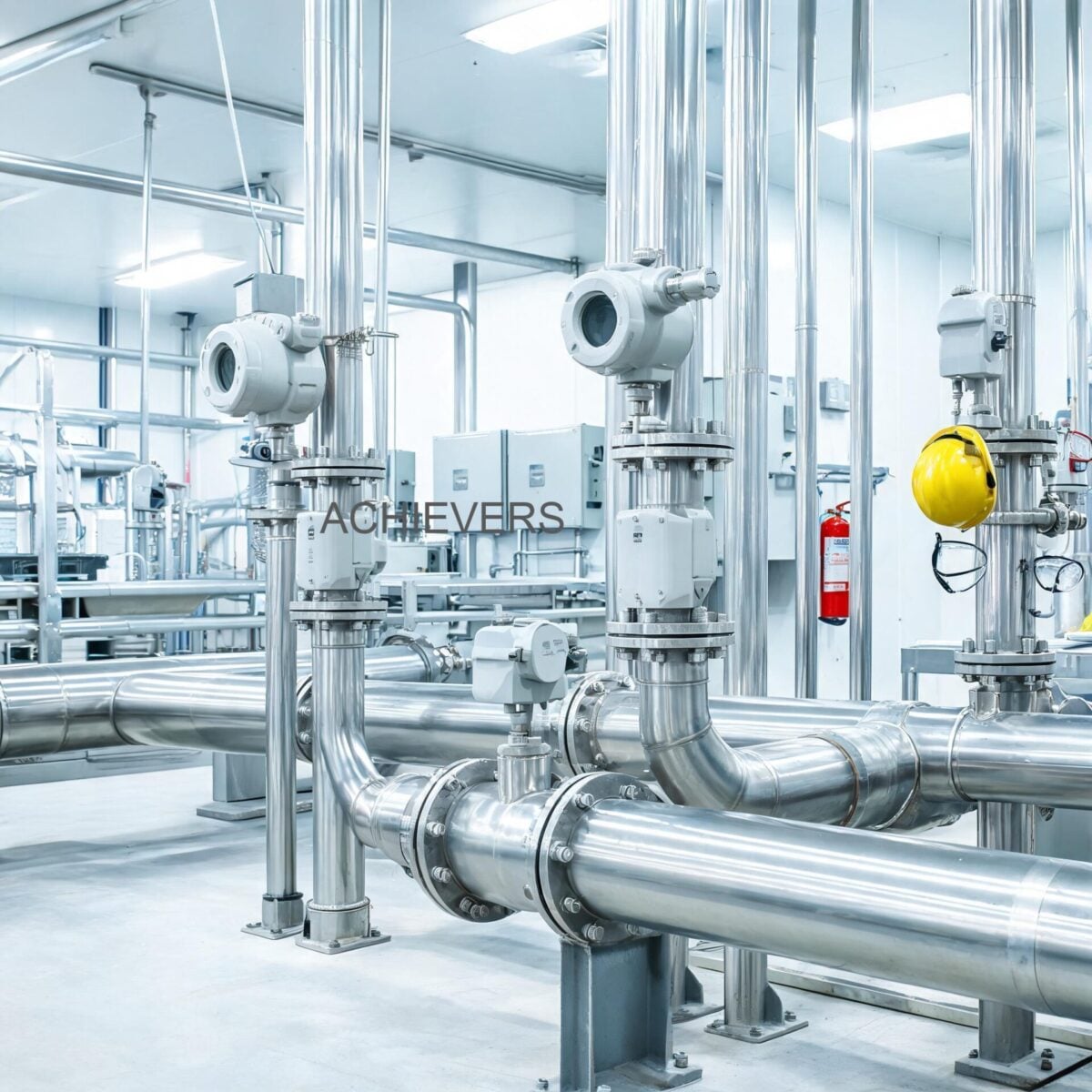
6. Extending Service Life in Global Industrial Conditions
Flow measurement systems in global industrial sectors—ranging from offshore oil platforms in the Middle East to heavy chemical processing in Northern Europe—face varying degrees of environmental hostility. Protecting the installation ensures decade-long service life.
Combating Extreme Temperatures and Thermal Shock
Vortex meters are frequently applied to saturated steam systems operating up to 350°C. Rapidly opening steam isolation valves causes violent thermal shock, which can fracture the delicate internal piezoelectric crystals. Always implement gradual warm-up procedures (cracking bypass valves) to slowly equalize thermal gradients. Furthermore, ensure the electronics housing is mounted away from the direct radiant heat path, utilizing the standoff neck to dissipate extreme temperatures.
Managing Pipeline Noise and Vibration
Because the technology relies on detecting microscopic pressure pulses, external mechanical vibration is the enemy of vortex shedding. Unbalanced pumps, rapidly stroking control valves, and inadequate pipe supports will generate acoustic noise that the sensor misinterprets as flow. Ensure meters are installed with heavy-duty pipe clamps within 3 to 5 pipe diameters upstream and downstream. If vibration is unavoidable, utilize heavy mass-balanced meter bodies and sophisticated DSP (Digital Signal Processing) amplifier boards to filter out environmental noise.
Ensuring Environmental and Ingress Protection
In humid environments, coastal regions, or locations subject to heavy monsoon downpours, the integrity of the transmitter housing is paramount. Capillary action can draw moisture through improperly sealed conduit entries directly into the terminal block. Always use IP67 or NEMA 4X rated cable glands. For installations in hazardous ATEX or IECEx zones, ensure flameproof pathways are lightly coated with approved non-hardening grease to prevent thread galling, while maintaining the required explosion-proof gap tolerances.
Addressing Fluid Contamination
While immune to minor particulates, heavy slurry or highly viscous fluids (where Reynolds numbers drop below 10,000) will dampen vortex formation, causing the meter to stop reading entirely. For fluids with high particulate loading, install an upstream Y-strainer and incorporate regular strainer blowdowns into the preventative maintenance routine to ensure the velocity profile remains uniform and unobstructed before it hits the bluff body.
By rigorously applying these maintenance, inspection, and environmental mitigation strategies, instrumentation engineers can guarantee that their flow measurement loops deliver the absolute precision required for advanced process control and utility accounting.
FAQ
Q: How frequently should a vortex flow meter be recalibrated?
A: Because the Strouhal number relies on fixed mechanical geometry, true calibration drift is extremely rare. However, for ISO or regulatory compliance, electronic loop verification and multivariable sensor (pressure/temperature) calibration should be performed annually.
Q: Can this technology measure highly viscous fluids like heavy fuel oils?
A: Generally, no. Vortex shedding requires a turbulent flow profile, typically dictating a Reynolds number above 20,000 for linear accuracy. Highly viscous fluids operate in the laminar flow regime, which prevents distinct vortices from forming behind the bluff body.
Q: What causes the meter to display a flow rate when the line isolation valves are completely closed?
A: This phenomenon is almost always caused by mechanical pipe vibration transferring to the piezoelectric sensor. Adjusting the transmitter's low-flow cutoff setting or adding robust pipe supports around the installation will eliminate these false readings.
Q: How does the inbuilt compensation feature work?
A: Gases and steam are highly compressible, meaning their density changes dramatically with process pressure and temperature. The inbuilt multivariable sensors continuously measure the live process temperature (up to 350°C) and pressure (up to 20 kg/cm2) to calculate the precise fluid density, providing an accurate, real-time mass flow output.
Q: Do I need straight pipe runs upstream of the meter?
A: Yes, flow profile uniformity is critical. A minimum of 15 to 20 pipe diameters (15D-20D) of straight, unobstructed pipe is typically required upstream, and 5 pipe diameters (5D) downstream, depending on the complexity of prior piping elbows or valves.
Q: Can the piezoelectric sensor be removed without draining the pipeline?
A: This depends on the specific model. While standard flanged and sandwich/wafer units require total line depressurization, specialized "insertion type" configurations feature a mechanical retraction mechanism and isolation ball valve, allowing sensor servicing under live pressure.
Q: What happens if the bluff body gets coated with scale or rust?
A: Any buildup that alters the physical width or geometry of the bluff body will directly change the vortex shedding frequency. This leads to persistent measurement errors, usually registering as an artificially high or low flow rate. Chemical cleaning is required to restore original accuracy.
For expert technical assistance in sizing, replacing, or configuring advanced flow measurement solutions for your specific process conditions, contact Lumen Instruments today. Please provide your line size, target fluid, operating pressure, temperature, and specific integration requirements (Modbus/4-20mA) so our engineering team can accurately recommend the exact Vortex Flow Meter configuration required to optimize your plant’s efficiency.