
Refueling heavy earth-moving machinery (HEMM) in remote open-pit mines, quarries, and massive construction sites presents a uniquely hostile fluid dynamics challenge. Standard off-the-shelf commercial pumps rapidly fail when exposed to the continuous ingress of silica dust, high-amplitude vehicular vibrations, and the severe pressure drops associated with long-hose reel deployments. For instrumentation and plant engineers, specifying Fuel Transfer Pumps requires moving beyond basic flow rate capacities to carefully evaluating suction lift physics, dynamic head constraints, and integrated motor protection under strictly intermittent power conditions.
In a mobile fuel bowser scenario, downtime is exceptionally costly. If the diesel transfer system fails, multiple multi-million-dollar excavators, haul trucks, and generators stop operating. This engineering guide details the mechanical specifications, deployment protocols, and sizing logic for utilizing heavy-duty Fuel Transfer Pumps in global harsh-site environments, ensuring consistent high-volume diesel delivery regardless of ambient extremes.
1. Industry Overview: The Fluid Challenge
Mobile diesel bowsers operate in environments characterized by massive ambient temperature swings, heavy airborne particulates, and constant mechanical shock. Diesel fuel itself presents measurement and handling challenges: its viscosity fluctuates significantly with temperature changes, and condensation within bulk tanks frequently introduces water and microbial contamination, creating highly abrasive sludge.
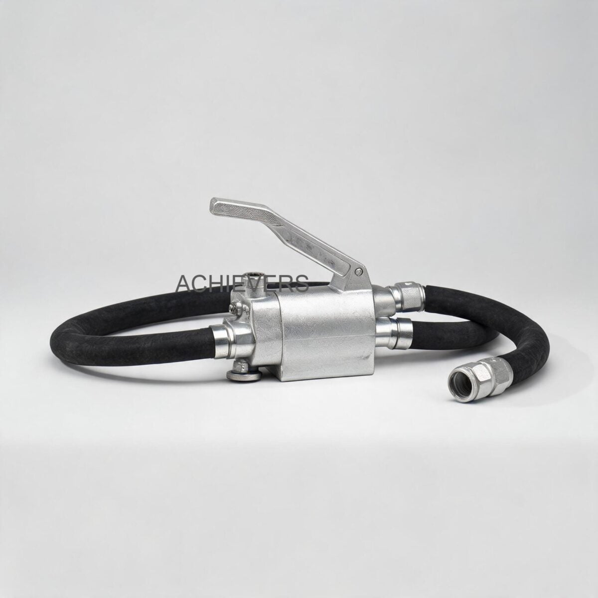
When deploying a Fuel Transfer Pumps system on a mobile service truck, engineers must account for the fluid friction generated by pumping high-viscosity diesel through 15 to 30 meters of reinforced rubber hose, often concluding in an automatic shut-off nozzle. This setup creates substantial backpressure. Standard centrifugal pumps cannot self-prime adequately in these top-draw tank configurations and lack the volumetric efficiency required to overcome high discharge head pressures. Furthermore, electrical availability on mobile bowsers is strictly limited to vehicle battery banks (12V or 24V DC), demanding a pump motor with high starting torque but an optimized current draw to prevent rapid battery depletion.
2. Product Capabilities Matched to Industry Needs
Selecting the correct positive displacement architecture is critical to overcoming the environmental and fluidic challenges of the mining and heavy construction sectors.
| Industry Requirement | Fuel Transfer Pump Feature | How It Addresses the Need |
| :— | :— | :— |
| Top-Draw Bulk Tank Refueling | Self-priming rotary vane design | Creates a high vacuum on the suction port, enabling 2 to 4 meters of vertical suction lift without requiring a foot valve or manual priming. |
| High Backpressure Operations | Integrated By-pass Valve | Recirculates fluid internally when the delivery nozzle is closed, preventing instantaneous hydraulic shock and motor stalling. |
| Mobile DC Power Constraints | Permanent Magnet Stator Motors | Provides high starting torque on 12V/24V DC systems while optimizing current draw (e.g., 21A on a 24V 80 L/min system). |
| Harsh Environment Ingress | IP55 Motor Protection Grade | Shields internal electrical components from heavy dust storms and low-pressure water jets common in washdown areas. |
| Continuous Mechanical Shock | Die-Cast Aluminum & Cast Iron Bodies | Eliminates hairline fractures associated with plastic or thin-stamped housings when mounted on vibrating chassis. |
| Contaminated Fluid Risks | Built-in Strainer | Captures large particulate matter (rust, tank scale) before it can enter the pumping chamber, protecting the acetal resin vanes. |
| Rapid Turnaround Times | High-Yield Flow Options | Achieves delivery rates of 40 L/min, 70 L/min, 80 L/min, and up to 120 Litre/Min, minimizing HEMM downtime during shift changes. |
| Weight Limitations on Skids | Sintered Steel Rotor / Acetal Vanes | Delivers maximum durability while keeping overall net weight exceptionally low (e.g., CE-40DC weighs just 3 KGS). |
3. Technology Comparison & Decision Matrix
To provide a comprehensive view of industrial fuel transfer pump supplier specifications, we must compare the fundamental positive displacement and kinetic pumping technologies used in hydrocarbon transfer.
Technology Comparison Table
| Parameter | Rotary Vane Pump (CE Series) | External Gear Pump | Centrifugal Pump |
| :— | :— | :— | :— |
| Primary Fluid Match | Diesel, Kerosene (Low-to-medium viscosity) | Heavy Fuel Oils, Lube Oils (High viscosity) | Water, extremely light chemicals |
| Self-Priming Capability | Excellent (Fast dry-lift up to 4m) | Good (Slower, requires wet gears) | Poor (Requires flooded suction) |
| Flow Stability at High Head | High (Volumetric efficiency > 85%) | Very High (Virtually no slip) | Low (Flow drops rapidly as head rises) |
| Tolerance to Particulates | Moderate (Acetal vanes wear gradually) | Low (Gears jam on hard particulates) | High (Open impellers pass solids) |
| RPM Requirements | High (e.g., 2800 RPM for CE-40DC) | Low to Moderate (typically < 1500 RPM) | Very High (2900 – 3600 RPM) |
| By-pass Integration | Easily integrated into pump body | Usually requires external relief loops | Not required (impeller can slip in fluid) |
'When to Use This Technology' Decision Matrix
- Specify Rotary Vane DC Pumps (CE-40DC, CE-70-A-DC, CE-80-DC): When deploying mobile diesel bowsers, skid tanks, or construction yard pickup trucks where fast self-priming, high flow rates (up to 120 L/min), and 12V/24V electrical architecture are the limiting factors.
- Specify External Gear Pumps: When transferring highly viscous fluids, such as cold motor oils, heavy lubricants, or unheated heavy fuel oil (HFO), where the high torque and tight tolerances of gears are required to move thick fluids.
- Specify Centrifugal Pumps: Only when transferring vast quantities of diesel in a stationary, gravity-fed (flooded suction) bulk terminal layout, where the pump sits completely below the tank fluid level.
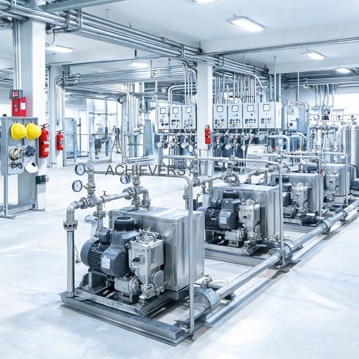
4. Typical Installation Scenarios in This Industry
Scenario 1: High-Volume Mobile Bowser Deployment
In open-pit mining operations, specialized service trucks travel to stationary excavators to supply diesel. The pump is mounted directly to the vehicle chassis near the tank base. A CE-80-DC unit running on the vehicle's 24V system provides 80 L/min output. Because of the long 20-meter discharge hose mounted on a spring-rewind reel, friction loss is high. The pump's integrated by-pass valve is essential here; when the operator shuts the automatic nozzle at the excavator, the by-pass valve opens instantly, preventing the high-velocity fluid column from generating a destructive water-hammer effect back into the pump housing. Integrating these systems alongside Mobile Diesel Dispensers ensures accurate volume tracking for operational auditing.
Scenario 2: Remote Generator Skid Tanks
Remote drilling sites rely on heavy diesel generators that draw fuel from day tanks. These tanks are often L-shaped and require flexible, low-profile installations. A CE-40DC is utilized to transfer diesel from a delivery truck into the day tank, or from a primary bulk skid into the day tank. The die-cast aluminum construction is lightweight, and the pump's 30-minute duty cycle easily accommodates the transfer of 1,200 liters in a single, uninterrupted batch before thermal stabilization is required.
Scenario 3: Earth-Moving Machinery Primary System Integration
For heavy agricultural or mining machinery, transfer pumps are often hard-wired into the equipment's primary electrical system to allow the vehicle to self-load fuel from stationary IBC totes or drums left in the field. The CE-70-A-DC (rated for 70 L/min, 4A current draw, 10m head) is mounted onto the tractor or excavator frame. Its IP55 protection grade is crucial here, as it survives aggressive high-pressure washdowns and heavy rain exposure without electrical shorting.
5. Engineering Specifications and Flow Sizing Logic
Accurate specification requires mapping the pump's capability to the physical limitations of the site. Below are the core technical data sets for high flow diesel transfer systems:
- CE-40DC Specifications: 40 L/min flow rate, 2800 RPM, Cast iron body with anti-corrosion paint, Acetal resin vanes, Sintered steel rotor, 3/4 inch I/O, 3 KGS net weight. 12V/24V DC.
- CE-70-A-DC Specifications: 70 L/min flow rate, 10m maximum head, 2 to 4m suction lift, 3/4 inch I/O. Current draw of 4 Amps.
- CE-80-DC Specifications: 80 L/min flow rate, 1 inch I/O. Current: 44A on 12V DC, 21A on 24V DC. 11 KGS net weight.
- Maximum High-Yield Options: Up to 120 Litre/Min for specialized ultra-high flow demands.
Engineering Sizing and Calibration Note
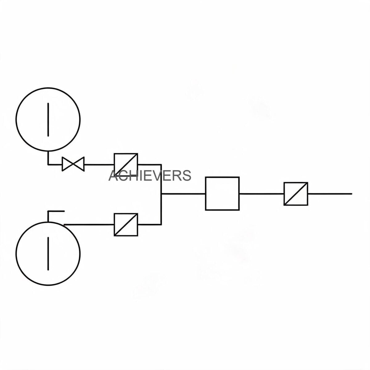
When selecting a DC transfer pump, engineers must calculate the Total Dynamic Head (TDH) to ensure the pump will not stall.
TDH = Elevation Head + Friction Head Loss + Pressure Head
Friction head loss is severely impacted by hose diameter. Using a 3/4 inch hose for an 80 L/min pump over a 15-meter run will create massive friction, forcing the pump into premature by-pass mode. For flow rates exceeding 60 L/min, engineers must step up to a 1-inch internal diameter (ID) hose.
Furthermore, electrical cable sizing is paramount. The CE-80-DC pulls 44A on a 12V system. If the cable run from the vehicle battery to the pump is 6 meters, engineers must use heavy-gauge copper wiring (minimum 4 AWG to 2 AWG) to calculate and mitigate voltage drop. A 10% voltage drop will reduce motor RPM, exponentially dropping the volumetric flow rate and causing the pump motor to overheat as it struggles to overcome mechanical inertia.
6. Compliance, Accuracy, and Protection Requirements
High flow diesel transfer operates within a highly regulated safety and metrology framework globally.
- Motor Protection and Duty Cycles: The motors on these units are designed for intermittent service, specifically a strict 30-minute work cycle. Operating beyond this limit without allowing the stator to cool can degrade the permanent magnets and burn the brush motor commutators. Thermal overload protectors are required to shield the motor.
- Ingress Protection: An IP55 rating dictates that the unit is protected against hazardous dust ingress and low-pressure water jets from any direction.
- Fluid Cleanliness (ISO 4406): While the pumps feature a built-in strainer, transferring fuel to modern Tier 4 final diesel engines (which feature high-pressure common rail injectors) requires downstream micro-filtration.
- Measurement and Accuracy: Transfer pumps themselves move fluid but do not measure it. For fuel custody transfer and consumption auditing, these pumps must be paired with precision Turbine Flow Meters on the discharge side, ensuring batch accuracies of +/- 0.5% or better.
7. Installation and Deployment Procedure
Strict adherence to mechanical and electrical engineering principles during installation prevents premature vane wear and motor failure. Follow this standard deployment protocol for mobile fuel transfer systems:
- Calculate Net Positive Suction Head Available (NPSHa): Position the pump as low as physically possible relative to the fuel tank. While the pump supports 2 to 4 meters of suction lift, minimizing vertical lift prevents fluid cavitation inside the rotor housing.
- Mount with Vibration Isolators: Secure the die-cast aluminum or cast iron pump base to the vehicle chassis using rubber anti-vibration dampeners to isolate the pump from high-frequency vehicular shock.
- Install Rigid Suction Lines: Use non-collapsible, steel-wire reinforced suction hose. Standard rubber hose will collapse under the vacuum generated by the rotary vanes, starving the pump.
- Wire for Minimal Voltage Drop: Connect the DC motor directly to the vehicle's battery bank using adequately sized copper cables (accounting for the 44A draw on 12V systems). Ensure an in-line fuse is installed as close to the battery terminal as possible.
- Verify By-pass Valve Operation: Briefly dead-head the pump by closing the discharge nozzle. Ensure the internal by-pass valve cracks open smoothly and allows recirculation without stalling the motor. Note: Never operate in by-pass mode for more than 2 to 3 minutes, as fluid friction will rapidly heat the trapped diesel.
- Conduct Thermal Duty-Cycle Testing: Run the pump under normal load for 20 minutes. Check the motor housing temperature and verify that electrical connections are not generating excess resistive heat.
8. Selection Checklist for This Industry
Before finalizing procurement for heavy-duty fuel management systems, plant managers and procurement heads should verify the following parameters:
- System Voltage Match: Confirm whether the mobile fleet utilizes 12V or 24V electrical architecture. (e.g., specifying the CE-70-A-DC 24V version for heavy earth-moving equipment).
- Required Flow Rate: Match the flow rate to the machinery tank size. An 80 L/min pump fills a 400-liter excavator tank in 5 minutes; a 40 L/min pump takes 10 minutes.
- Duty Cycle Adherence: Ensure the total batch volume can be transferred within the pump's 30-minute continuous operation limit.
- Suction Lift Constraints: Measure the vertical distance from the bottom of the deepest bulk tank to the pump inlet; it must not exceed 4 meters.
- Fluid Compatibility Check: Confirm the fluid is diesel, kerosene, or light fuel oil. These pumps are not rated for highly volatile fluids like aviation gasoline (Avgas) or highly viscous gear oils.
- Port Sizing: Match the pump inlet/outlet (e.g., 3/4 inch for CE-40DC, 1 inch for CE-80-DC) to the existing hose reels to avoid restrictive pipe bushings.
- Filtration Integration: Ensure adequate space exists between the pump discharge and the hose reel to mount a particulate/water-absorbing spin-on filter.
- IP Rating Verification: For exterior chassis mounting, mandate minimum IP55 protection to survive environmental exposure.
FAQ
Q: Can these rotary vane pumps be run dry?
A: They are capable of running dry for a very brief period (typically less than 30 seconds) during the initial self-priming phase. Prolonged dry running will rapidly overheat and disintegrate the acetal resin vanes due to a lack of fluid lubrication.
Q: Why is there a strict 30-minute duty cycle on DC fuel transfer pumps?
A: DC brush motors with permanent magnet stators generate significant internal heat during operation. The 30-minute limit ensures the motor windings and commutators do not exceed their thermal threshold. The pump must be allowed to cool to ambient temperature before the next cycle.
Q: What causes the pump motor to stall or blow fuses immediately upon startup?
A: This is almost always caused by a blocked suction line, a seized rotor due to ingested debris, or insufficient electrical current reaching the motor due to undersized wiring (voltage drop).
Q: How does the internal by-pass valve function?
A: When the delivery nozzle is closed, pressure spikes in the discharge line. The internal spring-loaded by-pass valve is forced open by this pressure, allowing the fluid to loop directly from the discharge port back to the suction port within the pump body.
Q: Can I use a 3/4 inch hose on an 80 L/min pump?
A: It is highly discouraged. Pushing 80 liters per minute through a 3/4 inch hose creates severe fluid friction, significantly reducing the actual flow at the nozzle and potentially forcing the pump to run partially in by-pass mode. Always use a 1-inch ID hose for flows above 60 L/min.
Q: Are these pumps suitable for transferring heavy engine oils?
A: No. Positive displacement vane pumps are engineered for low-to-medium viscosity fluids like diesel and kerosene. High viscosity fluids will overload the motor and prevent the centrifugal force from adequately pushing the vanes against the pump housing.
Q: How do ambient temperature extremes affect pump performance?
A: In sub-zero temperatures, diesel fuel can gel, dramatically increasing its viscosity and causing the pump to draw higher electrical current. In extreme heat, the motor will reach its maximum thermal threshold faster, requiring shorter duty cycles to prevent internal component damage.
To engineer a resilient and highly efficient mobile refueling infrastructure, accurate fluid data is paramount. Contact our instrumentation team today with your specific application details—including required flow capacity, fluid viscosity, operating voltage, and site environmental conditions—so we can specify the exact Fuel Transfer Pumps and integrated flow measurement solutions tailored to your operational demands.