
In Indian industrial operations—ranging from petrochemical plants in Gujarat to mining sites in Odisha—diesel is a critical, high-cost resource. At current fuel prices, even a 1% measurement error during high-speed diesel (HSD) decantation or batching can result in financial losses running into lakhs of rupees annually. Plant managers and procurement heads frequently face a frustrating scenario: the supplier's transport tanker dip shows one quantity, while the plant’s Diesel Flow Meters register a significantly different volume.
Determining whether the Diesel Flow Meters are under-reading (registering less than actual flow) or over-reading (registering more than actual flow) is the first step in resolving these expensive disputes. Often, perfectly functional Diesel Flow Meters are discarded and replaced—at costs ranging from ₹9,999 to ₹62,499—when the actual root cause is system-level physics, such as air ingress, viscosity shifts due to extreme Indian ambient temperatures, or bypass leakage.
This guide provides a methodical diagnostic workflow for instrumentation engineers to troubleshoot quantity mismatches, isolate accuracy issues, and restore reliable volumetric measurement to your fuel transfer systems.
1. Quick Reference: How Diesel Flow Meters Works
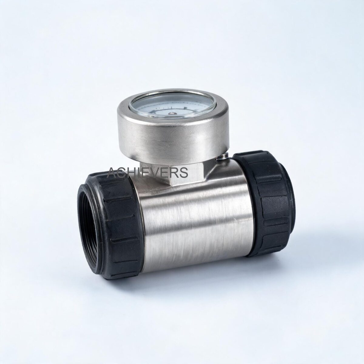
To diagnose measurement errors, you must first understand the fundamental operating principle of the instrumentation. Diesel Flow Meters primarily utilize Positive Displacement (PD) technology. A positive displacement meter directly measures the volume of the liquid passing through it by repeatedly entrapping the fluid.
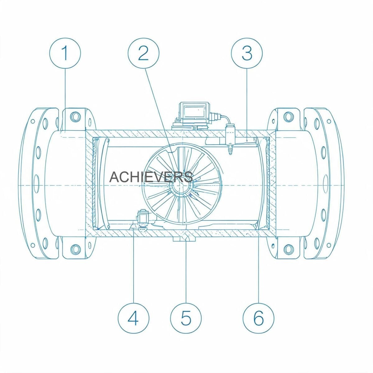
You can visualize this process as repeatedly filling a bucket with liquid, then dumping the contents downstream. The number of times the "bucket" is filled and emptied directly correlates to the total volumetric flow. Within the meter body, entanglement is typically achieved using turning parts (like oval gears, rotary vanes, or nutating discs) that form moving seals between each other and the flow meter casing.
Because the rotating parts have extremely tight tolerances, these seals prevent the liquid from bypassing the measurement chamber without being quantified—a phenomenon known as "slippage." The rotation is then detected either mechanically (driving a standard register) or magnetically (generating pulse outputs for digital displays or RS-485 communication).
The Slippage and Viscosity Dynamic
In fluid administration, increasing thickness (viscosity) actually decreases slippage and increases the pressure drop across the flow meter. Interestingly, precision can genuinely improve at low flow conditions in a given positive displacement meter when fluid viscosity increases, because the internal clearances are better sealed by the thicker fluid. Conversely, if diesel temperature rises significantly (e.g., during peak summer in Rajasthan reaching 45°C+), viscosity drops, slippage increases, and the meter may marginally under-read at low flow rates.
Engineering Formula: Volumetric Flow Calculation
The basic calculation governing positive displacement meters is:
Q = V_trap * N * Volumetric Efficiency
Where:
Q = Total Volumetric Flow Rate
V_trap = Volume of the measurement chamber (the "bucket")
N = Rotational speed of the internal gears/vanes
Volumetric Efficiency = 1 – (Slippage Volume / Total Volume)
Technology Comparison Table: Flow Measurement for Diesel
Plant engineers often ask why they should specify a PD meter over other technologies. No single-technology site provides an unbiased view. Below is a comparative analysis comparing Positive Displacement against other common industrial technologies like Turbine Flow Meters and Electromagnetic Flow Meters.
| Parameter | Positive Displacement (PD) Meters | Turbine Flow Meters | Electromagnetic (Mag) Meters |
| — | — | — | — |
| Measurement Principle | Volumetric (Mechanical entrapment) | Velocity (Rotor speed) | Faraday’s Law of Induction |
| Suitability for Diesel | Excellent (Diesel lubricates moving parts) | Good (For clean, low-viscosity diesel) | Incompatible (Diesel is non-conductive; Mag meters require >5µS/cm) |
| Accuracy (Standard) | ±0.5% to ±0.2% of reading | ±0.5% to ±1.0% of reading | ±0.2% to ±0.5% of reading (for conductive fluids only) |
| Viscosity Handling | High (Accuracy improves with viscosity) | Low (Viscosity spikes cause massive under-reading) | High (Independent of viscosity) |
| Straight Pipe Requirement | None (Can be installed next to elbows/valves) | High (Typically 10D upstream, 5D downstream) | Moderate (5D upstream, 3D downstream) |
| Cost Range (Indian Market) | ₹9,999 – ₹62,499+ | ₹15,000 – ₹80,000+ | ₹25,000 – ₹1,50,000+ |
| Pressure Drop (Delta P) | Moderate to High (Increases with viscosity) | Low to Moderate | Zero (Unobstructed flow tube) |
"When to Use This Technology" Decision Matrix
Use this matrix to determine if Positive Displacement Flow Meters are the correct specification for your application:
- Choose PD Meters When:
- High precision (±0.5% or better) is mandatory for custody transfer or inventory control.
- Plant piping layout is constrained and lacks the straight pipe runs required by velocity meters.
- Operating with liquids that have lubricating properties (Diesel, LDO, HFO, Lubricants).
- Flow rates vary significantly, and you need high accuracy at the low end of the flow range.
- Avoid PD Meters When:
- Pumping highly abrasive or dirty liquids containing particulate matter (unless heavy upstream filtration is possible).
- Operating far above the maximum specified pressure drop limit, which will prematurely wear internal bearings.
- Fluid contains large, shifting amounts of entrained gas or air bubbles without an air eliminator.
2. Troubleshooting Matrix: Diagnosing Quantity Mismatches
When a fuel quantity mismatch occurs, you must systematically categorize the symptom. Over-reading generally points to air entrapment, while under-reading points to mechanical wear, high pressure drop bypass, or increased slippage.
Below is an extensive troubleshooting matrix for Diesel Flow Meters deployed in harsh Indian industrial environments.
| Symptom | Likely Cause | Diagnosis Steps | Fix |
| — | — | — | — |
| Consistent Over-Reading (Meter shows 1050L, tank received 1000L) | Air ingress/Gas bubbles | Check for vortexing in source tank, leaks in suction piping, or dry runs when tank empties. | Install an Air Eliminator upstream. Repair suction leaks. Maintain minimum tank head. |
| Consistent Under-Reading (Meter shows 950L, tank received 1000L) | Rotor/Vane wear causing excess slippage | Inspect measuring chamber for worn sealing surfaces. Run meter at minimum flow rate; if slippage is high, meter will stall or read zero. | Replace internal rotors/gears. Recalibrate meter K-factor if wear is minor and linear. |
| Zero Reading (Fluid flows but display is dead) | Mechanical jam or broken coupling | Check if fluid is actually flowing. Remove register to see if magnetic drive coupling is rotating. | Clean measuring chamber of debris. Replace sheared coupling pins. |
| Zero Reading (Digital Output) | Power fault or faulty pulse transmitter | Measure voltage at transmitter terminals. Check for pulse output using an oscilloscope or DMM on Hz setting. | Restore stable power (use UPS/stabilizer to counter voltage fluctuations). Replace faulty Hall-effect sensor. |
| Erratic/Jumping Readings | Electrical noise (EMI) or severe flow pulsation | Check RS-485/Pulse cable shielding. Look for VFD cables routed parallel to meter signal cables. Check pump type (diaphragm pumps cause pulsation). | Re-route signal cables. Ground cable shield at one end only. Install pulsation dampeners if using pulsating pumps. |
| Progressive Under-Reading over time | Bearing wear / Increased friction | Measure pressure drop across meter. An abnormal increase in pressure drop indicates bearings are failing, slowing the rotors. | Replace bearings. Ensure operating flow rate does not exceed maximum pressure drop specification. |
| Display Error / Garbled LCD | Moisture ingress or overheating | Check IP65/IP67 enclosure seals. Inspect for condensation inside the glass (common during Indian monsoons). | Replace desiccant packs. Reseal enclosure with high-quality industrial silicone. Shield meter from direct sunlight. |
| Leakage from Meter Body | Blown gaskets / O-rings | Visually inspect mating flanges and register housing. Check if system pressure exceeded the meter’s pressure rating. | Replace gaskets/O-rings with Viton/PTFE. Ensure pressure relief valves are functional. |
| Loud Grinding Noise | Particulate contamination (Dirt/Rust) | Isolate meter and open Y-strainer. Check for metal shavings or rust flakes from old plant piping. | Clean strainer basket. Flush meter body. Upgrade to a finer mesh size (e.g., 80 mesh for diesel). |
| Valve Not Responding (Batch Systems) | Solenoid failure or signal loss | In batching setups, check the relay output from the meter or batch controller to the pneumatic/electric valve. | Replace burnt solenoid coils (common with unstable Indian power). Verify 4-20mA or relay control signals. |
3. Step-by-Step Field Diagnosis Procedure
When a massive mismatch is reported between the receipt and the meter, do not immediately dismantle the equipment. Follow this standardized 8-step field diagnostic procedure.
Tools Required: Standard spanner set, multimeter (with Hz frequency measurement), clear 20-liter or 50-liter Legal Metrology stamped standard volumetric measure (SVM) can, pressure gauges, and protective gear (PPE).
- Safety and System Isolation: Before beginning, shut off power to Fuel Transfer Pumps and electronic registers. Close upstream and downstream isolation valves to secure the meter.
- Visual & Environmental Inspection: Inspect the pipeline for any physical damage, leaks at the flanges, or signs of tampering with the calibration seals. Look for bypass valves that might be partially open, allowing unmetered diesel to circumvent the meter.
- Bleed Air and Check Eliminator: Air bubbles are measured as volume by a PD meter. If the supply tanker runs completely dry, air is forced into the system. Ensure the mechanical air eliminator valve is functioning and the float mechanism is not jammed by dirt.
- Strainer Inspection: Unbolt the upstream Y-strainer. In India, transport tankers often contain rust, sludge, or adulterated fuel. A plugged strainer can cause cavitation in the pump, leading to vapor bubbles that artificially inflate the meter reading. Clean the 80-mesh/100-mesh filter.
- Volumetric Calibration Test (Bucket Test): This is the definitive test to prove accuracy.
- Procure a Legal Metrology certified 20L or 50L Standard Volumetric Measure.
- Dispense exactly 50 liters into the calibrated vessel at the normal operating flow rate.
- Compare the vessel's reading against the meter's mechanical or digital register.
- Calculate the error percentage: Error % = [(Meter Reading – Actual Volume) / Actual Volume] * 100.
- Flow Rate Validation: Check if the system is operating within the specified flow range. Operating a 100 LPM meter at 5 LPM will result in massive under-reading due to high percentage slippage. Operating it at 150 LPM will cause over-speeding, premature bearing wear, and eventual catastrophic failure.
- Pressure Drop (Delta P) Test: Install pressure gauges immediately upstream and downstream of the meter. Run the system. A high pressure drop indicates excessive internal friction or fluid viscosity higher than calibrated parameters. Operating over the pressure drop limits will severely damage bearing assemblies.
- Electronics and Pulse Verification: For digital models, navigate to the calibration menu. Check the K-Factor (pulses per liter). Ensure no unauthorized personnel have altered this value. If using an external batch controller, use the multimeter to verify that clean, square-wave pulses are reaching the controller without interference.
4. Installation and Setup Errors That Cause Ongoing Problems
Many troubleshooting calls end with the realization that the meter was never installed correctly. Diesel Flow Meters require strict adherence to piping best practices to maintain their ±0.5% accuracy.
| Installation Error | Resulting Symptom | Engineering Correction |
| — | — | — |
| Absence of Upstream Strainer | Sudden meter stalling, internal scratches, high slippage, under-reading. | Install a Y-strainer or basket strainer (min 80 mesh) immediately upstream of the meter. |
| Absence of Air Eliminator | Over-reading by 2% to 10%, especially when emptying storage tanks or tanker trucks. | Install an air/vapor eliminator on the highest point upstream of the meter to vent entrained gas. |
| Installing at Pipeline High Points | Air gets trapped in the meter body, causing erratic flow and over-reading. | Install the meter at lower elevations or in vertical lines with upward flow to keep the pipe full of liquid. |
| Reverse Flow Installation | Meter runs backward (mechanical) or fails to output correct directional pulses. | Ensure the flow arrow cast on the meter body strictly aligns with the fluid transfer direction. |
| Lack of Downstream Backpressure | Fluid flashes into vapor (cavitation) inside the meter, causing over-reading and gear damage. | Install a backpressure valve or elevate the downstream pipe to keep the meter completely flooded with liquid. |
| Vibration from Nearby Pumps | False pulse generation on digital meters; premature wear on mechanical registers. | Decouple the meter using flexible stainless-steel bellows and provide rigid structural support to piping. |
5. Preventive Maintenance to Avoid Recurrence
Once you have diagnosed and fixed the issue, a rigid preventative maintenance (PM) schedule is vital. Indian site conditions are exceptionally harsh. Heavy monsoon rains create extreme humidity that penetrates poorly sealed electronics, while summer dust storms introduce particulate matter into open breathers.
- Weekly: Inspect all flanges and seals for weeping leaks. Verify that calibration seals (lead seals or digital locks) are intact.
- Monthly: Open and clean the upstream strainers. During monsoon, check the fuel tanks for water ingress. Water has a different viscosity than diesel and lacks lubricity, which can cause internal rust and scaling on the measuring gears. Drain water from the bottom of storage tanks regularly.
- Quarterly: Conduct a 50-liter or 100-liter calibration proving test using a Legal Metrology certified proving can. Adjust the mechanical calibration screw or digital K-factor if a drift of more than 0.2% is observed.
- Bi-Annually: For meters exposed to the elements, replace silica gel desiccant packs inside the electronic housings to prevent display screen failure. Re-apply anti-corrosion spray to external bolts and mechanical register gears.
6. When to Call Service vs. Fix Yourself
Knowing the limits of field maintenance prevents permanent damage to precision instrumentation.
What you can fix yourself (Field-Fixable):
- Cleaning strainers and un-jamming air eliminators.
- Recalibrating the meter using the internal calibration mechanism or digital K-factor adjustment, provided you have a certified proving measure.
- Replacing external digital displays, pulse transmitters, or mechanical registers.
- Replacing O-rings and flange gaskets to stop external leaks.
When to call factory service (Return to Base):
- Measuring Chamber Damage: If dirt has deeply scored the oval gears or the internal casing walls, the slip volume is permanently altered. The unit requires factory re-machining or complete internal replacement and bench calibration.
- Bearing Seizures: If the meter completely locks up due to over-speeding or lack of lubrication, replacing bearings in the field often leads to misalignment.
- Legal Metrology Certification: If your flow meter is used for custody transfer or retail sale, any breaking of the government-stamped seals requires a certified Legal Metrology inspector and an authorized service center to recalibrate and re-seal the unit according to PESO and BIS norms.
FAQ
Q: Why does my diesel flow meter read higher than the actual volume received from the tanker?
A: The most common cause of over-reading is air ingress. When the tanker empties, air is sucked into the hose and passes through the meter. Since Positive Displacement meters measure volume, they will measure the trapped air bubbles as if they were fluid. Installing an air eliminator resolves this.
Q: Can changes in ambient temperature affect the accuracy of the meter?
A: Yes. Extreme temperature shifts change the viscosity of diesel. In peak Indian summers, diesel becomes thinner (lower viscosity), which slightly increases internal slippage in the meter, potentially causing minor under-reading at very low flow rates.
Q: How often do I need to calibrate my industrial flow meter?
A: For internal accounting, a bi-annual calibration check using a certified proving measure is recommended. If the meter is used for custody transfer (buying/selling), calibration must adhere to the Legal Metrology Act, 2009, which typically requires annual stamping by a designated officer.
Q: What happens if I operate the meter above its maximum rated flow capacity?
A: Operating above the maximum flow rate causes excessive pressure drop across the internal components. This leads to over-speeding of the gears, rapid bearing wear, and eventual catastrophic failure of the flow meter mechanism.
Q: My digital flow meter display is blank, but fuel is flowing. What is wrong?
A: This usually indicates an electrical fault. Check the power supply and ensure it is protected from voltage fluctuations. If battery-operated, replace the internal lithium battery. Also, inspect the magnetic pickup sensor to ensure it hasn't failed or been disconnected.
Q: Is it necessary to install a straight run of pipe before a positive displacement meter?
A: No. Unlike Turbine or Electromagnetic meters, PD meters do not require a fully developed flow profile. You can install them directly adjacent to elbows, valves, or T-junctions without sacrificing accuracy.
Q: Why is my meter suddenly making a grinding noise?
A: A grinding noise indicates heavy particulate contamination (rust, scale, or dirt) has bypassed the strainer and entered the tight-tolerance measuring chamber. Stop the flow immediately, isolate the meter, and clean the internal chamber to prevent permanent scoring.
If your plant is continuously facing diesel reconciliation mismatches, or if you are setting up a new bulk fuel decantation facility, selecting the correct meter specification is critical. Contact our engineering team with your required flow rate, pipeline size, maximum pressure, and specific site conditions (e.g., coastal humidity or high dust environments) so we can recommend the exact Diesel Flow Meters and accessory setup to guarantee ±0.5% accuracy for your operations.