
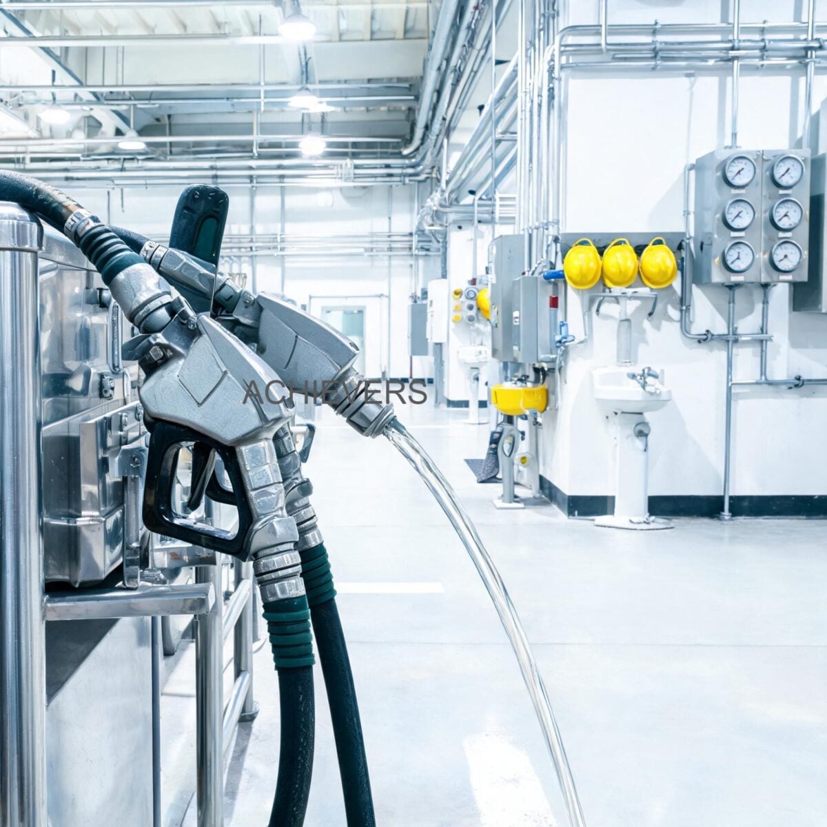
Industrial fluid dispensing operations cannot tolerate unpredictable fueling cycles. High-velocity diesel delivery to heavy mining equipment, remote generators, chemical processing vats, or logistics fleets demands precise, uninterrupted flow control. When automatic shutoff mechanisms fail—manifesting as premature shutoff, violent splashback (kickback), or severe foaming—the resulting asset downtime, environmental safety hazards, and direct fuel loss immediately impact plant operating expenses.
Replacing hardware without fundamental diagnostic isolation often leads to recurring failures. The root cause usually resides in a mismatch between pump pressure, fluid dynamics, tank venting, and the internal pneumatic logic of the delivery hardware. This comprehensive engineering guide examines the internal mechanics and troubleshooting methodologies for Fuel Nozzles experiencing erratic shutoff behaviors. By directly linking physical symptoms to Venturi vacuum failures, flow velocity restrictions, and dispensing setup geometries, plant managers and procurement heads can effectively eliminate dispensing bottlenecks.
1. Quick Reference: How Fuel Nozzles Work
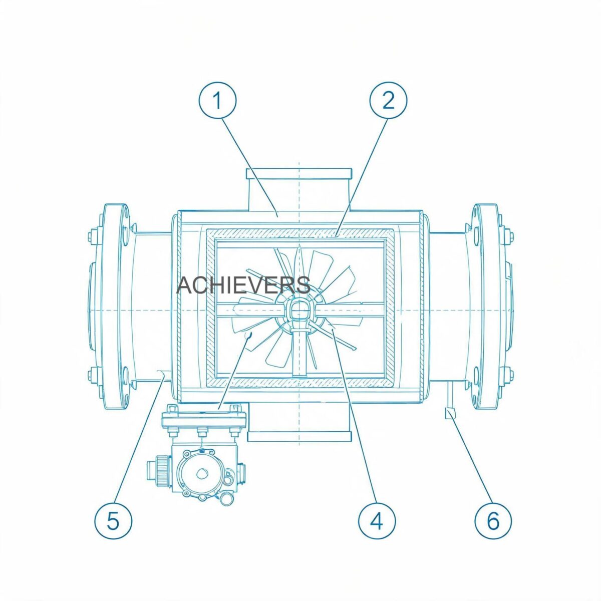
To diagnose dispensing failures, operators must first understand the hydro-pneumatic operating principles governing Fuel Nozzles. Automatic shutoff nozzles are not electronically controlled; they operate entirely on fluid dynamics, specifically the Venturi effect, utilizing a localized pressure drop to trigger a mechanical release.
The Venturi Mechanism and Bernoulli's Principle
Inside the nozzle, the main valve controls the flow of diesel. As fuel passes through the main body and enters the 13/16 inch spout, it passes over a small Venturi ring. According to Bernoulli’s Principle, the restriction causes fluid velocity to increase and pressure to decrease, creating a localized vacuum.
Engineering Formulation for Venturi Pressure Drop:
Delta P = 0.5 x fluid density (rho) x (Velocity_2^2 – Velocity_1^2)
This vacuum continuously draws air through a small "sense port" located at the tip of the spout. As long as air flows freely through this port, the vacuum is relieved, and the main valve remains latched open. When fluid (or dense foam) covers the sense port, air can no longer enter. The vacuum immediately intensifies, pulling a flexible diaphragm upward. This diaphragm displacement trips the mechanical latch pin, slamming the main valve shut via spring tension.
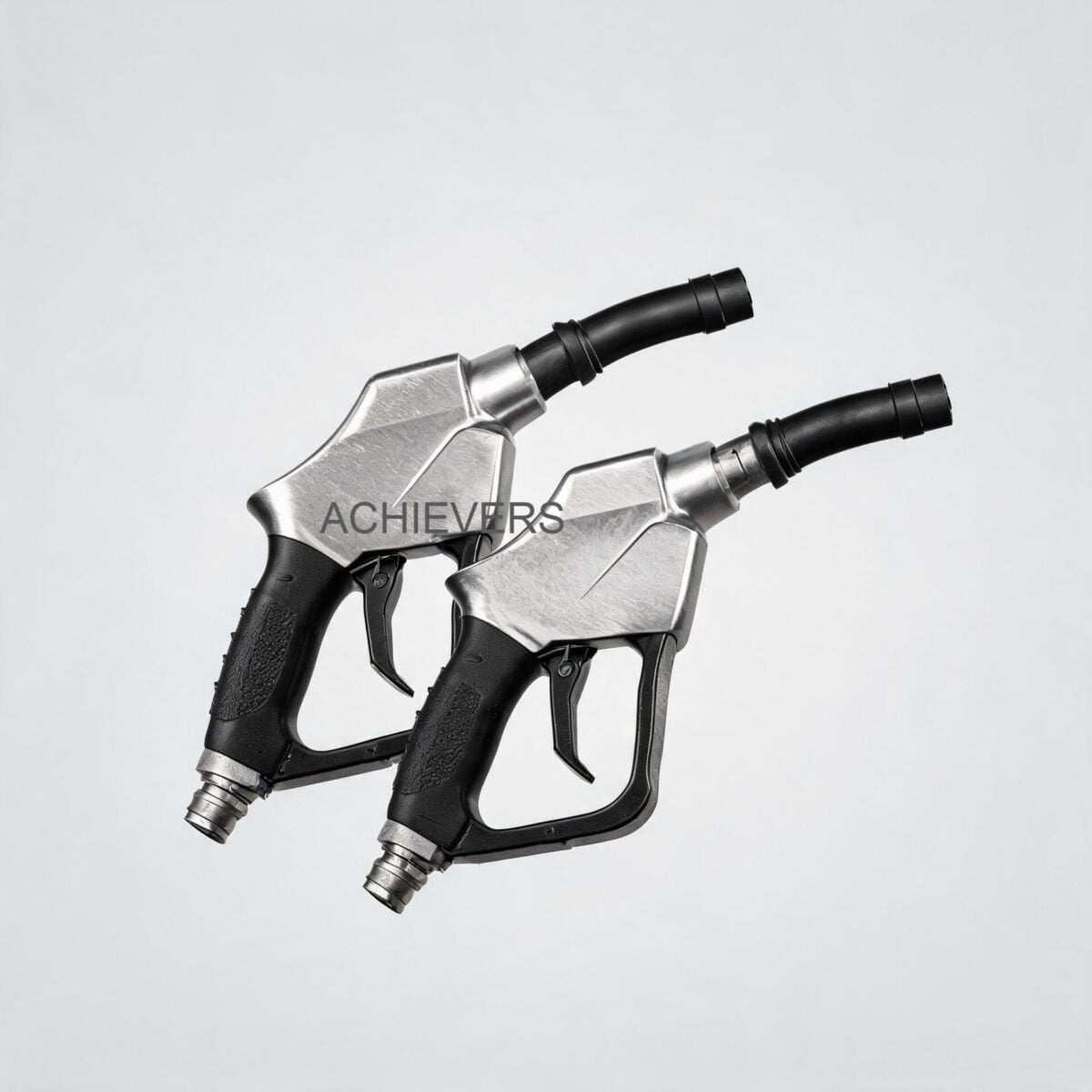
Technical Specifications for Baseline Diagnosis
Understanding baseline specifications is critical before attempting repairs. The Fuel Nozzles detailed in this guide operate within the following strict parameters:
- Inlet Thread Size: BSP 3/4 inch
- Spout Diameter: 13/16 inch
- Maximum Flow Rate: 0 to 60 Liters per minute (L/min)
- Maximum Operating Pressure: 0.18 MPa (1.8 Bar / approx. 26.1 PSI)
- Net Weight: 1.14 kg
- Insulator Color: Red
- Integration: Optional dual-measurement digital flow meter (mechanical or electronic sorts)
Exceeding the 0.18 MPa pressure rating or forcing flow rates above 60 L/min will inherently override the Venturi logic, leading to immediate failure modes such as kickback or continuous premature shutoff.
Integrated Flow Measurement: Technology Comparison Table
When fuel nozzles are paired with onboard digital flow meters, the underlying metering technology dictates performance in different environments. Because we supply a wide breadth of measurement technologies, it is vital to compare how integrated nozzle meters stack up against inline Turbine Flow Meters or Positive Displacement options.
| Parameter | Integrated Turbine Nozzle Meter | Integrated Positive Displacement (Gear) | Inline Electromagnetic Meter | Inline Vortex Meter |
| — | — | — | — | — |
| Measurement Principle | Fluid velocity turning a bladed rotor | Volumetric cavity trapping fluid | Faraday's Law of Induction | Karman vortex shedding |
| Typical Accuracy | +/- 1.0% | +/- 0.5% | +/- 0.2% to 0.5% | +/- 0.75% to 1.0% |
| Viscosity Tolerance | Low to Medium (Best for Diesel/Water) | High (Excellent for heavy oils/lubes) | Independent of viscosity | Low (Requires turbulent flow) |
| Pressure Drop | Low to Moderate | Moderate to High | Zero (Unobstructed pipe) | Moderate |
| Ideal Application | Mobile dispensing, fleet refueling | High-accuracy custody transfer of oils | Conductive liquids (Water/Chemicals) | High-temp steam or gas |
| Field Calibratable? | Yes (via K-factor adjustment) | Yes | Typically factory calibrated | Typically factory calibrated |
2. Troubleshooting Matrix
When a dispensing system fails, the symptoms must be isolated to either the delivery hardware, the pumping system, or the receiving tank geometry. Use this matrix to systematically trace operational faults back to their mechanical or fluid-dynamic origins.
| Symptom | Likely Cause | Diagnosis Steps | Fix |
| — | — | — | — |
| Premature Shutoff (Continuous) | Sense port at spout tip is blocked | Inspect the 13/16 inch spout tip for dirt, dried fuel residue, or ice. | Clean sense port with compressed air or a soft wire brush. |
| Violent Splashback (Kickback) | System flow exceeds 60 L/min or 0.18 MPa limit | Install an inline pressure gauge before the BSP 3/4" inlet. Check pump bypass valve. | Adjust pump bypass to regulate pressure below 0.18 MPa. |
| Diesel Foaming in Fill Pipe | Flow velocity too high for tank neck geometry | Observe fuel entry. Check if drop tube is missing or if filling splashes directly against walls. | Reduce flow rate via nozzle trigger notches; install an extended drop tube. |
| Nozzle Fails to Shut Off Automatically | Vacuum diaphragm ruptured or sense tube cracked | Remove from service immediately. Test vacuum logic by plugging the sense port while flowing into a safe container. | Rebuild nozzle with new diaphragm kit or replace entire unit. |
| Leakage at Swivel / Inlet Joint | Worn O-rings or damaged BSP 3/4" threads | Wipe joint dry, pressurize system without dispensing, and observe for seepage. | Replace swivel O-rings; apply compatible thread sealant (e.g., PTFE paste for diesel). |
| Leakage from Spout (Dripping) | Main poppet valve seat is scored or has debris | Shut off pump. Hold nozzle downward to see if residual fluid drips continuously. | Disassemble main valve, inspect poppet, clean seat, replace poppet O-ring. |
| Digital Meter Reads Zero Flow | Rotor jammed or dead batteries (if electronic) | Remove meter faceplate. Check battery voltage. Blow air through to test rotor spin. | Replace batteries; clear debris from turbine rotor chamber. |
| Digital Meter Output is Erratic | Entrained air in the fuel line (cavitation) | Inspect suction side of the pump for leaks. Look for bubbles in fuel. | Tighten pump suction fittings; ensure suction lift isn't causing cavitation. |
| Latch Pin Fails to Engage | Bent trigger mechanism or worn latch plate | Visually inspect the metal trigger guard and stepped latch plate for deformation. | Replace latch plate or trigger assembly. |
| Flow Restricted (Below Specs) | Clogged inlet strainer | Remove swivel at the BSP 3/4" connection and inspect the mesh strainer. | Remove and clean the metal mesh strainer in solvent. |
3. Step-by-Step Field Diagnosis Procedure
When splashback and continuous shutoff stall operational workflows, field technicians must follow a methodical testing procedure to prevent misdiagnosis. Randomly swapping out fuel nozzles or adjusting pump regulators without data will compound the failure.
Required Tools for Diagnosis:
- Calibrated pressure gauge with a BSP 3/4 inch inline T-fitting.
- Graduated proving bucket (20L to 50L) for flow rate testing.
- Compressed air source (regulated to low pressure).
- Multimeter (for digital meter diagnostics).
- Standard wrenches, picks, and ATEX-approved flashlight.
Diagnostic Procedure:
- Safety Isolation and Baseline Setup:
- Visual Inspection of the Spout:
- Inlet Strainer Verification:
- Static Pressure Test:
- Dynamic Flow Testing (Volume & Velocity):
- Vacuum Logic Test (Auto-Shutoff Verification):
- Tank Venting Assessment:
- Digital Meter Calibration Check (If Equipped):
Ensure the dispensing area complies with local ATEX or API safety zones. Lock out the pump power. Equip required PPE (gloves, safety glasses). Prepare the 50L proving bucket.
Examine the 13/16 inch spout. Locate the vacuum sense port near the tip. Verify it is perfectly clear of debris, burrs, or physical crushing. A dented spout will alter the Venturi geometry and destroy the shutoff logic.
Disconnect the nozzle from the dispensing hose at the BSP 3/4 inch inlet. Extract the mesh filter strainer. If blocked with rust or sediment, flow is starved, reducing velocity over the Venturi and causing delayed or erratic shutoff. Clean and reinstall.
Install the inline pressure gauge between the hose and the nozzle. Turn on the pump but do not open the nozzle. Record the static pressure. It must not heavily exceed the 0.18 MPa (1.8 Bar) rating. If static pressure is 3.0 Bar, the pump's internal relief bypass is failing or incorrectly set.
Dispense exactly 20 Liters into the proving bucket while timing the process. Calculate the Liters per minute. If the flow exceeds 60 L/min, the fluid velocity is overpowering the tank's ability to vent air, causing diesel to shoot back up the neck (kickback).
While dispensing fuel into the bucket at a medium flow rate, carefully place a gloved finger completely over the sense port at the tip of the spout. The nozzle should violently "click" and shut off within 0.5 seconds. If it continues to flow, the internal diaphragm is ruptured or the internal vacuum tube is compromised.
If the nozzle passes the bucket test but fails on the heavy equipment tank, the problem is tank pressure. Inspect the equipment's fuel tank vent breather. Blocked breathers force displaced air back out the fill neck against the incoming fuel, causing immediate splashback and foaming.
If the onboard flow meter shows discrepancies, compare the digital readout to the physical volume in the proving bucket. If the meter reads 20L but only 18L was dispensed, adjust the electronic K-factor or mechanical calibration screw according to the manufacturer's formula.
4. Installation and Setup Errors That Cause Ongoing Problems
Optimal hardware cannot compensate for poor system engineering. Procurement heads often source high-quality components, such as Mobile Diesel Dispensers and automatic nozzles, only for installation crews to introduce systemic faults.
Below is an analysis of common installation errors, their symptoms, and required corrections.
| Installation Error | Resulting Symptom | Engineering Correction |
| — | — | — |
| Pump Pressure Exceeds 0.18 MPa Limit | Extreme kickback, severe foaming, poppet valve fails to close completely. | Install a pressure reducing valve or adjust the pump's internal bypass spring to maintain 1.5 to 1.8 Bar at the nozzle inlet. |
| Mismatched Hose Thread Sealing | Weeping or heavy leakage at the BSP 3/4" swivel connection. | Do not use standard pipe tape on parallel threads. Ensure the O-ring is seated and use liquid PTFE thread sealant rated for hydrocarbons. |
| Lack of Drop Tube in Receiving Tank | Diesel drops several meters through air, entraining massive amounts of gas (foaming). | Modify the tank fill neck to include a drop tube that extends to the bottom of the tank, allowing submerged, bottom-up filling. |
| Insufficient Tank Vent Sizing | Tank pressurizes during 60 L/min fill, forcing air up the fill neck. Premature shutoff every 5 seconds. | Upgrade tank vent breather capacity. The vent must allow air displacement at a rate equal to or greater than 60 L/min. |
| Oversized Nozzle on Small Fill Neck | The 13/16" spout leaves no annular space in a narrow neck for air to escape. | Change nozzle to a smaller spout variant or reduce fill rate. Ensure fill neck inner diameter is significantly larger than 13/16". |
| Bypassing the Swivel Joint | Rigid hose connection causes operator to twist the nozzle body, applying torque. | Always install a dual-plane swivel. Torque warps the nozzle body, causing internal poppet valve binding and leaks. |
Decision Matrix: When to Use This Technology
Determining if an automatic shutoff nozzle with an integrated digital meter is the correct engineering choice depends on site constraints.
- Use Automatic Shutoff Nozzles When: Dispensing into blind tanks (generators, heavy earthmovers) where overfill poses an immediate environmental or fire hazard. Ideal for standard flow rates up to 60 L/min at low pressures (0.18 MPa).
- Use Manual Nozzles When: Gravity-fed systems are used, where pressure is too low to create the required Venturi vacuum (e.g., overhead agricultural tanks with less than 0.5 Bar static head).
- Use Integrated Digital Meters When: Decentralized inventory tracking is required without the infrastructure of a large commercial fuel island.
- Switch to High-Flow Nozzles (1 inch+ Spouts) When: Refueling large off-highway mining trucks where 60 L/min is too slow, and operations require 150+ L/min delivery.
5. Preventive Maintenance to Avoid Recurrence
Reactive maintenance in fluid transfer results in catastrophic fuel spills or severely degraded operational efficiency. Establishing a robust preventive maintenance schedule ensures that automatic dispensing technologies function flawlessly in harsh global environments, whether in offshore marine platforms or remote mining outposts.
Weekly Inspections:
- Sense Port Cleaning: The tip of the spout routinely collects dirt, grease, and atmospheric dust. A blocked port is the #1 cause of continuous premature shutoff. Wipe the spout daily and ensure the port is unobstructed.
- Visual Leak Check: Inspect the BSP 3/4" inlet joint and the main spout for any weeping. Hydrocarbon seepage indicates failing elastomer seals.
Monthly Inspections:
- Strainer Maintenance: Shut down the system pressure, remove the nozzle, and clean the inlet screen. Sediment from large storage tanks inevitably migrates down the pipeline.
- Swivel Lubrication: Test the swivel joint. If binding occurs, the operator will transfer torsional stress into the nozzle cast body. Lubricate or replace stiff swivels.
Bi-Annual Calibrations:
- Meter Proving: If using a digital flow meter, verify accuracy against a certified volumetric prover. Changes in diesel viscosity due to extreme seasonal temperature shifts can alter the slip-factor in positive displacement and turbine meters, requiring seasonal K-factor adjustments.
6. When to Call Service vs. Fix Yourself
Knowing the boundary between field-serviceable repairs and factory-level rebuilds prevents further damage to precision instrumentation.
Field-Fixable Issues:
Plant technicians should handle inlet blockages, battery replacements for digital flow meters, swivel O-ring replacements, spout cleaning, and K-factor calibrations. Minor leaks at the threads or a blocked inlet screen require standard tools and under 30 minutes of downtime.
Requires Factory Service or Full Replacement:
If the nozzle fails the vacuum logic test (does not shut off when the sense port is covered), the internal diaphragm is ruptured or the pneumatic channels are cracked. Opening the vacuum chamber in the field without calibration rigs often destroys the nozzle's precise trigger timing. Similarly, if the main cast aluminum body is warped from mechanical impact, or the internal poppet valve stem is bent, complete replacement is the safest, most cost-effective solution. In high-stakes environments, attempting to machine or bend internal valving can lead to a catastrophic failure to shut off, resulting in massive environmental spills.
FAQ
Q: Can I use this nozzle for high-viscosity fluids like gear oil or heavy lube oil?
A: No. These nozzles are calibrated for the specific gravity and viscosity of diesel, gasoline, and light motor oil. High-viscosity fluids will not achieve the necessary velocity to create the Venturi vacuum required for automatic shutoff, and they will severely restrict flow through the internal pathways.
Q: Why does the nozzle continuously shut off when filling my heavy machinery, even though the tank is empty?
A: This is usually caused by excessive pump pressure (exceeding 0.18 MPa), a blocked vent breather on the machinery's tank, or a blocked sense port on the nozzle spout. Check the static pressure of your pump first.
Q: Is the integrated digital meter suitable for ATEX / hazardous area zones?
A: You must verify the specific certification of the electronic meter module. While the mechanical nozzle relies entirely on fluid dynamics (safe for hazardous areas), electronic digital meters require specific intrinsically safe ATEX/CE approvals for use in explosive gas atmospheres.
Q: My flow rate is significantly lower than the rated 60 L/min. What is the restriction?
A: Begin by checking the metal mesh strainer located at the BSP 3/4 inch inlet for sediment buildup. If clear, check the fuel filters at your main dispensing pump, as heavily loaded filters will drop system pressure and reduce final flow velocity at the nozzle.
Q: Can I remove the automatic shutoff mechanism to force it to flow faster?
A: Absolutely not. Altering or disabling the automatic shutoff mechanism bypasses critical safety designs, violating international fueling standards (like API and CE guidelines) and creating a massive risk of environmental contamination via overfilling.
Q: How often do I need to calibrate the digital flow meter on the nozzle?
A: Calibration frequency depends on throughput and fluid cleanliness. For general industrial inventory tracking, a bi-annual calibration against a known volumetric proving bucket is standard. Sudden changes in ambient temperature (which affect diesel density and viscosity) may also necessitate a seasonal K-factor adjustment.
Q: What causes the digital flow meter to display erratic numbers without actual flow?
A: This "ghost reading" is typically caused by severe line vibration transmitting through the hose to the turbine rotor, or entrained air (bubbles) passing through the line due to a suction leak at the main pump.
If your facility is struggling with persistent dispensing bottlenecks, fluid metering inaccuracies, or requires an upgrade to heavy-duty fuel management systems, our engineering team can spec the correct hardware for your specific fluid dynamics. Contact us with your target flow rate, line pressure, fluid type, and site environmental conditions so we can quote the exact flow metering and dispensing solution your operation requires.