
Unplanned downtime in global process industries—whether in petrochemicals, water treatment, or food and beverage processing—often traces back to instrumentation failure. When a flow meter transmits an unstable 4–20 mA output, dosing pumps erraticate, batch controllers trip, and overall process control degrades. Properly diagnosing these issues before replacing expensive hardware is a critical skill for any plant engineer.
Often, perceived hardware failures in Electromagnetic Flow Meters are actually symptoms of process anomalies, grounding faults, or improper installation. A fluctuating zero-flow reading or a noisy analog output does not automatically warrant a complete sensor replacement. By utilizing a structured diagnostic workflow, instrumentation technicians can systematically isolate electrochemical noise, pipeline stray currents, and physical coating issues.
This comprehensive engineering guide breaks down the root causes of signal noise and zero-flow drift in Electromagnetic Flow Meters. It provides a step-by-step troubleshooting protocol designed for industrial environments, ensuring that plant managers and procurement heads make informed maintenance and replacement decisions based on empirical electrical testing rather than guesswork.
1. Quick Reference: How Electromagnetic Flow Meters Work
Understanding the fundamental physics behind Electromagnetic Flow Meters is the first step in diagnosing signal errors. These instruments operate on Faraday's Law of Electromagnetic Induction.
Engineering Formula (Faraday's Law):
E = k * B * D * V
Where:
- E = Induced voltage (proportional to flow velocity)
- k = Instrument constant
- B = Magnetic field strength
- D = Inner diameter of the pipe
- V = Mean velocity of the conductive fluid
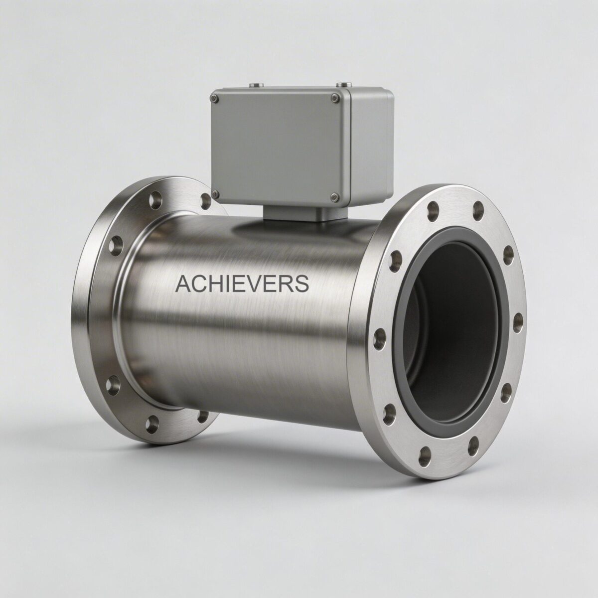
Inside the meter body, excitation coils generate a magnetic field (B) across the flow tube. As a conductive fluid passes through this field, it acts as a moving conductor, inducing a microvolt-level electrical signal (E) across two wetted electrodes.
Modern transmitters utilize Pulsed DC technology rather than continuous AC excitation. By rapidly pulsing the magnetic field on and off, the microprocessor measures the voltage during the "on" state and the baseline electrochemical noise during the "off" state. Subtracting the baseline eliminates zero-point drift, ensuring high stability and a clean, linearly proportional 4–20 mA DC output.
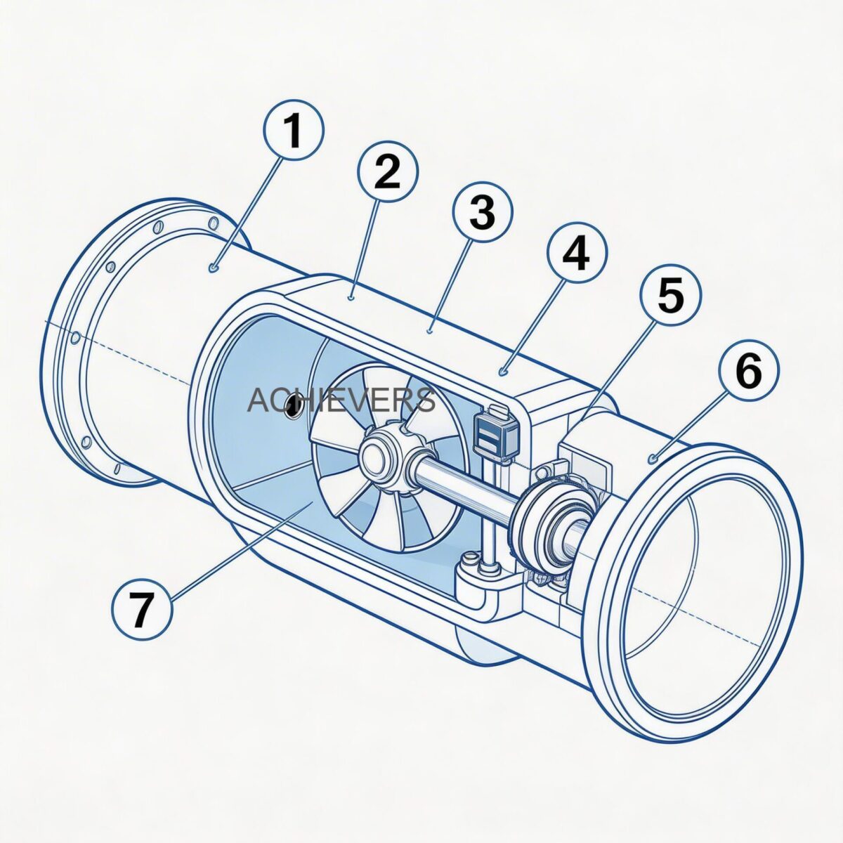
Key Components and Failure Modes:
- Electrodes (316L, Hastelloy, Titanium, Tantalum): Prone to chemical fouling, scaling, or galvanic noise if unmatched to the fluid.
- Liners (PTFE, PFA, F46, Neoprene): Can deform under extreme high temperature/vacuum conditions, leading to internal leakage.
- Excitation Coils: Susceptible to moisture ingress if the IP67/IP65 seal is compromised, resulting in short-to-ground faults.
2. Technology Comparison Table
No single flow measurement technology fits every application. When diagnosing chronic failures, it is worth verifying if a magmeter is actually the correct technology for your process conditions. Below is an engineering comparison between Electromagnetic Flow Meters, Turbine Flow Meters, and Vortex Flow Meters.
| Parameter | Electromagnetic Flow Meters | Turbine Flow Meters | Vortex Flow Meters |
| — | — | — | — |
| Measurement Principle | Faraday's Law of Induction | Mechanical Rotor Velocity | Von Karman Shedding |
| Fluid Constraint | Must be conductive (>= 5 µS/cm) | Clean liquids/gases only | Liquids, gases, and steam |
| Pressure Drop | Zero (Full bore design) | High (Mechanical obstruction) | Medium (Bluff body) |
| Moving Parts | None | Rotor, Bearings | None (Sensor only) |
| Viscosity Limit | Highly tolerant of thick slurries | Sensitive (requires calibration shifts) | Medium tolerance |
| Typical Accuracy | +/- 0.5% (Optional +/- 0.2%) | +/- 0.5% to 1.0% | +/- 0.75% to 1.0% |
3. Product Specifications and Capabilities
When verifying the operational limits of your installation, consult the baseline specifications of your installed hardware. Operating outside these parameters guarantees signal drift and sensor degradation.
General Operating Parameters:
- Medium Temperature Range: -10 to 150 degrees C
- Ambient Environmental Temperature: 0 to 55 degrees C
- Electrical Power Voltage: 220VAC 50Hz, or 24 VDC
- Power Consumption: Less than or equal to 15W
- Minimum Conductivity: Greater than or equal to 5 µS/cm
Model Variations & Specifications:
| Specification | Flange Type | Triclover Type | Battery Operated |
| — | — | — | — |
| Pipe Size Range | DN15 – DN1000 | DN15 – DN80 | DN15 – DN300 |
| Electrode Materials | 316L, Hc, Hb, Ti, Ta | 316L, Hc, Hb, Ti, Ta | 316L, Hc, Hb, Ti, Ta |
| Liner Materials | Neoprene, PTFE, PFA, F46 | PTFE, PFA, F46 | PTFE, PFA, F46 |
| Measuring Range | 0.2 ~ 2800 m3/h | 0.2 ~ 180 m3/h | 0.2 ~ 2500 m3/h |
| Accuracy Rating | +/- 0.5% (+/- 0.2% optional) | +/- 0.5% (+/- 0.2% optional) | +/- 1.0% of displayed value |
| Protection Class | IP65, IP67 | IP65, IP67 | IP65, IP67 |
| Target Application | Heavy industry, waste water | Food & Beverage, Pharma | Remote sites, no grid power |
'When to Use This Technology' Decision Matrix
- Use Electromagnetic Meters when: Pumping abrasive slurries, corrosive chemicals, wastewater, or food-grade liquids where zero pressure drop and a sanitary, free-pipe cross-section are mandatory.
- Do NOT use Electromagnetic Meters when: Pumping ultra-pure deionized (DI) water, reverse osmosis (RO) water, hydrocarbons, oils, or gases, as these fluids fall well below the 5 µS/cm conductivity threshold.
4. Troubleshooting Matrix
When an electromagnetic flow meter exhibits signal instability or failure, consult this comprehensive diagnostic matrix to isolate the root cause before dismantling the pipe.
| Symptom | Likely Cause | Diagnosis Steps | Fix |
| — | — | — | — |
| Zero Flow Reading but Fluid is Moving | Empty pipe or severely low conductivity | Check fluid conductivity; verify pipe is 100% full. | Reroute piping to ensure a full pipe (e.g., U-trap). |
| Erratic / Jumping 4-20 mA Output | Entrained air bubbles in the fluid | Monitor flow stability on transmitter; check upstream valves. | Increase backpressure; install air release valves upstream. |
| Signal Noise and Drift | Grounding failure or stray pipeline currents | Measure potential difference between fluid and meter body. | Install grounding rings; ensure equipotential bonding (< 1 ohm). |
| Display Freezes at a Constant Value | Transmitter microprocessor lock-up | Cycle power; check diagnostic error codes on display. | Hard reset the unit; replace main transmitter board if persistent. |
| Negative Flow Rate Displayed | Reverse installation or crossed electrode wires | Check flow arrow on sensor body; check wiring terminals. | Rotate meter 180 degrees or swap the electrode wire connections. |
| Flow Rate Reads Excessively High | Internal liner degradation or pipe scaling | Inspect internal bore for cross-sectional area reduction. | Clean the liner; descale the pipeline; replace liner if swollen. |
| "Empty Pipe" Alarm Always On | Coated or fouled electrodes | Measure electrode resistance to ground (should not be open). | Remove sensor and clean electrodes with appropriate solvent. |
| No Display / Dead Transmitter | Power supply failure or blown fuse | Verify 24VDC or 220VAC at terminals using a multimeter. | Replace internal fuses; check field wiring for shorts. |
| Output Signal Loss (0 mA) | Broken loop wire or burned analog output | Measure loop current at terminals and PLC receiving end. | Repair broken field cable; replace analog output card in transmitter. |
| Gradual Drift Over Months | Gradual electrode oxidation/fouling | Review historical trend data for slow, linear signal degradation. | Schedule periodic sensor cleaning; review chemical compatibility. |
5. Step-by-Step Field Diagnosis Procedure
When replacing an instrument is costly and requires halting production, use this definitive multimeter diagnostic procedure to determine if the fault lies in the sensor, the transmitter, or the field wiring.
Required Tools:
- True RMS Digital Multimeter (DMM)
- Megohmmeter (Insulation tester)
- Screwdrivers and terminal block tools
- Conductivity meter (for fluid sampling)
The 8-Step Diagnostic Protocol:
- Verify Fluid Conductivity and Pipe Fill: Extract a fluid sample and measure its conductivity. Ensure it strictly exceeds 5 µS/cm. Visually or acoustically confirm that the pipe is 100% full of liquid, not a liquid-gas mix.
- Isolate the Transmitter: Disconnect the power supply and wait 5 minutes for internal capacitors to discharge. Disconnect the sensor coil and electrode wires from the transmitter housing.
- Measure Coil Resistance: Using the DMM, measure the resistance across the two excitation coil terminals on the sensor. Depending on the size (DN15 to DN1000), a healthy coil typically reads between 40 ohms and 150 ohms. An infinite reading means an open or broken coil; 0 ohms means a dead short.
- Check Coil Insulation to Ground: Switch to the Megohmmeter (set to 500VDC max). Measure the resistance between either coil terminal and the external metal sensor body. A healthy meter must show high insulation, typically greater than 20 Megohms. If it reads low, fluid or moisture has breached the IP67 housing.
- Measure Electrode Resistance: With the pipe full of liquid, use the DMM to measure resistance between Electrode A and ground, then Electrode B and ground. Both readings should be relatively similar (within 10-20% of each other), typically between a few kilohms to a hundred kilohms, depending on the fluid.
- Detect Electrode Fouling: If the resistance measured in Step 5 is vastly different between the two electrodes (e.g., one reads 50 kOhm, the other reads 5 Megohm), one electrode is severely coated with insulating material (like grease or calcium).
- Verify Grounding Integrity: Switch the DMM to AC Volts. Measure between the fluid grounding point (grounding ring) and the plant earth ground. Any voltage greater than 1VAC indicates severe stray pipeline noise that will disrupt the millivolt-level Faraday signal. Install heavy-gauge grounding straps.
- Check Transmitter Output Calibration: Reconnect all wiring and power the unit. Access the transmitter's diagnostic menu and force a 12 mA output simulation. Check the PLC/DCS input. If the control room does not see exactly 12 mA (50% scale), your analog loop wiring is compromised or requires recalibration.
6. Installation and Setup Errors That Cause Ongoing Problems
Many troubleshooting calls are solved not by replacing parts, but by correcting fundamental installation errors that were made during the initial plant commissioning phase.
| Installation Error | Resulting Symptom | Engineering Correction |
| — | — | — |
| Insufficient Straight Pipe Run | Erratic flow rate, high noise | Ensure at least 5x Pipe Diameter (DN) upstream and 3x DN downstream of straight pipe. |
| Meter Installed at Highest Pipe Point | Entrained air, empty pipe errors | Relocate the meter to a low point or a vertical line with upward flow to ensure a full pipe. |
| Lack of Grounding Rings on Plastic Pipe | Wildly drifting 4-20mA output | Install metallic grounding rings on both flanges to bond the fluid to the sensor body ground. |
| Nearby VFD Power Cables | High-frequency signal interference | Route the meter's signal cables in dedicated, grounded steel conduit away from variable frequency drives. |
| Incorrect Gasket Alignment | Flow restriction, inaccurate high readings | Recenter gaskets so they do not protrude into the flow bore and alter the cross-sectional area. |
| Control Valve Placed Upstream | Cavitation, severe turbulence | Relocate flow control valves downstream of the flow meter. |
7. Preventive Maintenance to Avoid Recurrence
Electromagnetic flow meters are highly regarded for their "fit-and-forget" lack of moving parts, but "low maintenance" does not mean "zero maintenance." Implementing a proactive schedule preserves the +/- 0.5% accuracy over a decade of operation.
- Biannual Visual Inspections: Check the IP65/IP67 enclosure seals. In humid environments or outdoor installations subject to 0~55 degree C swings, condensation can accumulate inside the terminal box. Use silica gel desiccant packs or epoxy potting compound in the junction box.
- Electrode Cleaning Schedules: In wastewater or high-calcium applications, schedule pipeline shutdowns to mechanically wipe the electrodes and PTFE/PFA liner. Do not use abrasive wire brushes that could scratch the liner; use mild acid/base solvents compatible with the fluid.
- Verification of Earthing Connections: Plant vibrations can loosen the heavy copper grounding straps over time. Annually retorque the grounding cables on the flanges. A loose ground will immediately introduce 50Hz mains noise into the signal.
- Cable Shield Integrity: Ensure the shielded cables connecting remote sensors to transmitters are only grounded at one end (typically the transmitter side) to prevent ground loops.
8. When to Call Service vs. Fix Yourself
Knowing your technical limits ensures safety and prevents voiding factory warranties.
Field-Fixable Issues:
Plant engineers should easily handle grounding faults, loop wiring replacements, clearing fouled electrodes, updating parameters in the microprocessor (such as flow range or pulse output scaling), and rotating the display module. Adjusting the low-flow cutoff to eliminate zero-drip noise is also a standard field fix.
Issues Requiring Factory Service or Replacement:
If your multimeter diagnostics reveal an open excitation coil or a short to the sensor body, the internal potting has failed. This is not repairable in the field. Similarly, if the PTFE or F46 liner shows signs of swelling, blistering, or tearing, the entire sensor body must be replaced. Microprocessor boards that fail to output the forced 4-20mA signal despite receiving correct 24VDC power generally require swapping with factory-calibrated OEM boards.
FAQ
Q: Can electromagnetic flow meters measure the flow of diesel or hydrocarbons?
A: No. Diesel, fuel oils, and hydrocarbons are non-conductive (virtually 0 µS/cm). Magmeters require a minimum conductivity of 5 µS/cm to induce a readable voltage. For these fluids, positive displacement or turbine meters must be used.
Q: Why does my flow meter read flow when the line is shut off?
A: This is known as zero-flow drift. It is usually caused by an improperly grounded pipeline, electrochemical noise from coated electrodes, or a completely empty pipe. Setting a higher "low flow cutoff" value in the transmitter menu can mask minor pipe vibrations.
Q: What is the difference between IP65 and IP67 protection classes?
A: IP65 protects against low-pressure water jets from any direction, making it suitable for standard indoor washdowns. IP67 allows for temporary submersion in water up to 1 meter deep, which is critical for meters installed in pits that might flood.
Q: Can I shorten the cables on a remote-mounted transmitter?
A: Yes, but with extreme caution. The specialized signal cables carry microvolt-level signals. If you shorten them, you must ensure the shielding is perfectly re-terminated and not exposed to electromagnetic interference. Recalibration is usually not required just for shortening the cable.
Q: How often does an electromagnetic flow meter need calibration?
A: Because they have no moving parts to wear out, they do not suffer from mechanical drift. In clean fluids, they can run for 3 to 5 years without recalibration. However, regulatory standards in pharmaceuticals or municipal water often dictate mandatory annual verification.
Q: Why is my PTFE liner blistering?
A: Blistering or deformation of PTFE liners occurs when the fluid temperature exceeds the specified limits (up to 150 degrees C) combined with negative pressure (vacuum) conditions in the pipe. PFA or ceramic liners are better suited for high-vacuum, high-temperature applications.
Q: Are grounding rings strictly necessary if my pipes are metal?
A: If the metal pipes are internally unlined and well-bonded to plant earth, grounding rings may not be necessary. However, if the pipes are plastic, PVC, or internally lined with rubber/epoxy, metallic grounding rings are absolutely mandatory to complete the electrical measuring circuit.
For precise sizing, technical drawings, or to troubleshoot a complex flow measurement loop, reach out to our engineering support team. Provide your target Electromagnetic Flow Meters application details, including pipe diameter, fluid type, operating temperature, and conductivity, and our instrumentation specialists will help you select the exact liner, electrode material, and transmitter configuration for your facility's unique operational demands.