
Selecting the right flow measurement technology is rarely as simple as matching line sizes and pressure ratings. For Indian plant managers, instrumentation engineers, and procurement heads dealing with steam loops, compressed air networks, or high-temperature gases, understanding the underlying physics of Vortex Flow Meters is the difference between a highly accurate mass-flow balance and a chaotic, error-prone control loop.
While Vortex Flow Meters are frequently marketed as "install and forget" devices due to their lack of moving parts, their performance is strictly bound by aerodynamic laws. If your fluid velocity drops too low, the meter will literally stop seeing the flow. If your piping transmits pump vibrations, the meter might read a ghost flow. This technical deep-dive explains the von Kármán shedding principles, the digital signal processing required to maintain accuracy, and how to properly specify a Vortex Flow Meters for harsh Indian industrial conditions, from high-temperature pharmaceutical steam lines to fluctuating compressed air grids in manufacturing plants.
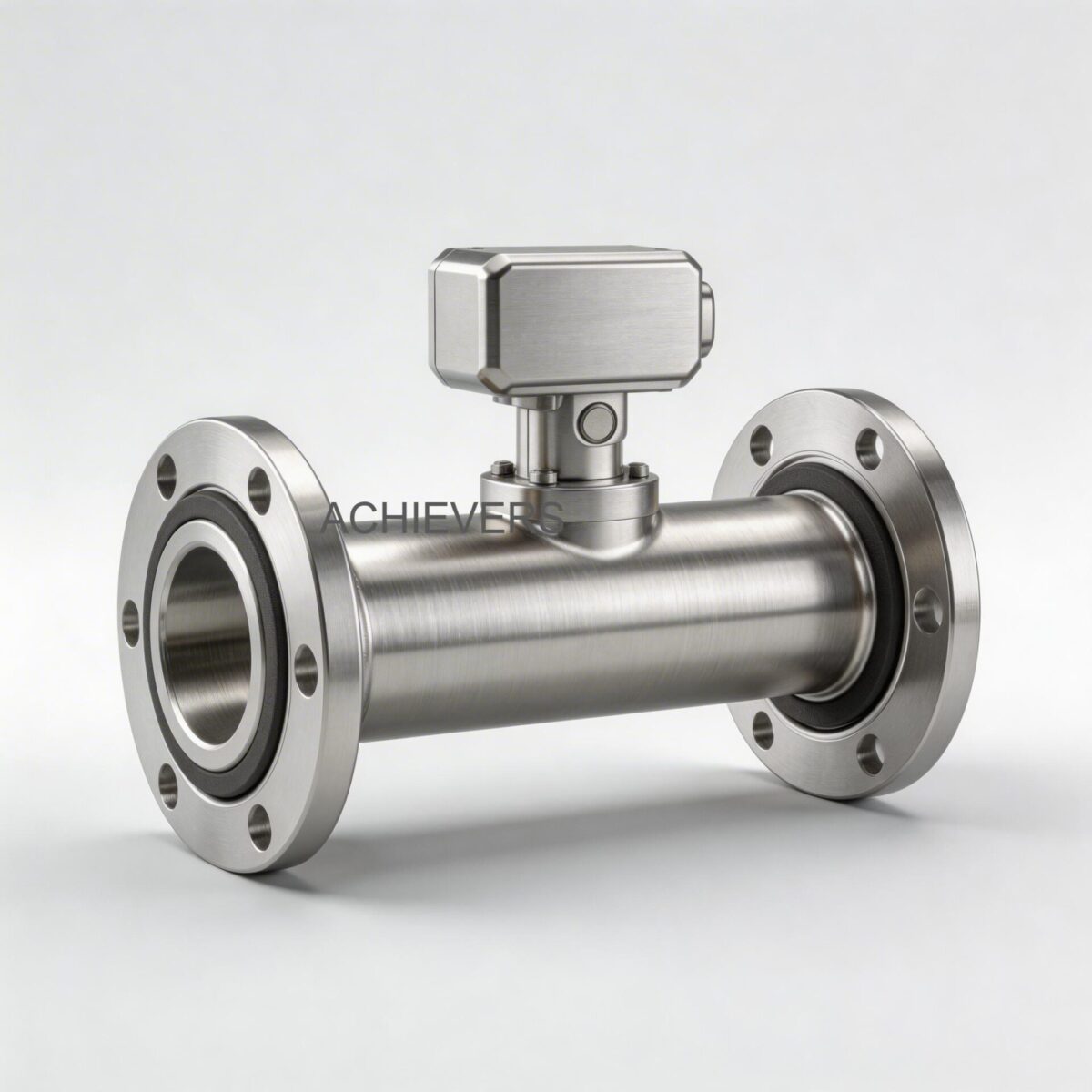
1. Working Principle: How Vortex Flow Meters Operate
The core operating principle of a vortex shedding meter relies on a fluid dynamics phenomenon known as the von Kármán effect. When a fluid passes an unstreamlined obstruction (known as a bluff body or shedder bar) placed perpendicular to the flow, it cannot negotiate the sharp angles smoothly. The fluid separates from the object, creating alternating areas of low and high pressure.
These pressure differentials cause vortices (swirls of fluid) to detach—or "shed"—from alternating sides of the bluff body. The frequency of this shedding is directly proportional to the fluid velocity.
The underlying physics is governed by a dimensionless parameter known as the Strouhal number (St). The relationship is expressed in the following engineering formula:
f = (St * V) / d
Where:
- f = Frequency of vortex shedding (Hz)
- St = Strouhal number (a constant for a specific bluff body design, typically between 0.15 and 0.25)
- V = Velocity of the fluid (m/s)
- d = Width of the bluff body (m)
Because the bluff body width (d) and the Strouhal number (St) are constant, the frequency of the vortices (f) is strictly linear and proportional to the velocity (V).
However, this linearity is entirely dependent on the Reynolds Number (Re) of the fluid. The Reynolds number represents the ratio of inertial forces to viscous forces:
Re = (Density * Velocity * Internal Pipe Diameter) / Dynamic Viscosity
Vortex shedding only remains stable and linear when the Reynolds number is highly turbulent—typically Re > 20,000. If the fluid is too viscous, or the velocity drops too low, the vortices dampen out and the meter stops registering flow. This is why these meters have a strict "turndown ratio" or low-flow cutoff.
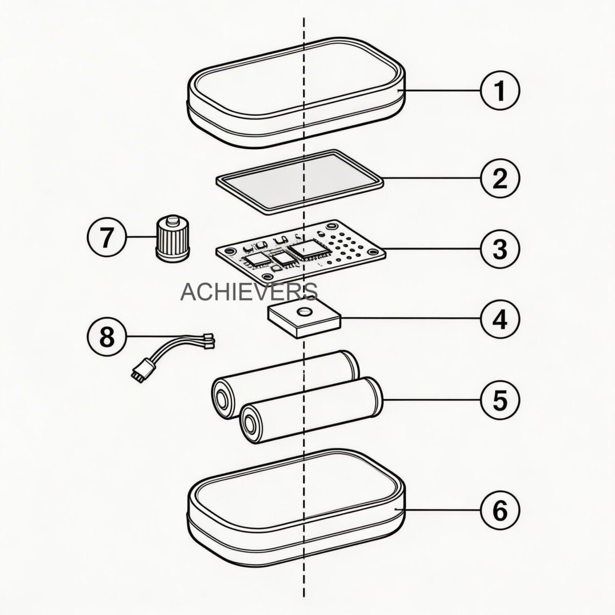
Signal Pickup and Processing
As the vortices shed, the alternating low-pressure zones exert a lateral force on the sensor—usually a piezoelectric crystal positioned behind the bluff body. This crystal generates a minute electrical charge (measured in pico-coulombs) corresponding to each vortex. A charge amplifier inside the transmitter converts this into a voltage, which is then processed, filtered for noise, and converted into standard industrial outputs like 4-20 mA or Modbus.
2. Complete Technical Specifications
To ensure reliable integration into your plant's Distributed Control System (DCS) or SCADA network, equipment must match your process constraints. Lumen Instruments manufactures the Achivers brand meters with the following confirmed specifications, making them suitable for rigorous Indian industrial environments, from 350 deg C boiler steam to pressurized gas networks.
| Parameter | Specification | Engineering Notes |
| :— | :— | :— |
| Line Size Capability | DN 15 to DN 300mm | Ensure line sizing matches required Reynolds number, not just existing pipe size. |
| Process Temperature | -50 to 350 deg C | Piezoelectric sensors are isolated from direct thermal stress; ideal for saturated and superheated steam. |
| Maximum Pressure | Up to 20 kg/cm2 | Suitable for most industrial steam, compressed air, and utility gas lines. |
| Signal Outputs | 4-20 mA, Pulses, RS 485 Modbus | Supports legacy analog loops and modern digital networking. |
| Compensation | Inbuilt Pressure & Temperature | Crucial for mass flow calculation of compressible fluids (gases/steam). |
| Power Supply | 24Vdc two-wire | Standard industrial loop power, highly resistant to voltage fluctuations. |
| Mounting Options | Flange type, Sandwich, Clamp On | Sandwich (wafer) reduces face-to-face dimensions; Flange offers higher pressure integrity. |
| Operating Principle | Von Kármán Vortex Shedding | No moving parts; immune to wear from clean, high-velocity fluids. |
| Wetted Materials | Typically SS316 / SS304 | Resistant to corrosion; suitable for petrochemical and food processing environments. |
| Typical Turndown | 10:1 to 15:1 | Varies by fluid density; gases have lower turndown limits than liquids. |
3. Performance Characteristics and Error Sources
A precision instrument requires a precision environment. While the baseline accuracy of a well-calibrated unit is typically ±0.75% to ±1.0% of rate for liquids and ±1.5% of rate for gases, Indian industrial site conditions often introduce specific error sources that instrumentation engineers must mitigate.
1. Piping Geometry and Flow Profile Distortion
Vortex meters demand a fully developed, symmetrical velocity profile. Valves, elbows, and reducers placed too close upstream disrupt the flow, causing asymmetrical vortex shedding. Standard engineering practice requires a minimum straight run of 15D to 20D (pipe diameters) upstream and 5D downstream. If space is tight, a flow conditioner must be installed.
2. Plant Vibration (Common-Mode Noise)
In heavy industries like steel manufacturing or power generation, structural vibrations from large centrifugal pumps or compressors can transmit through the piping. If the pipe vibrates at a frequency similar to the expected vortex shedding frequency, the piezoelectric sensor will pick it up as a "false flow." High-quality meters use Digital Signal Processing (DSP) and mass-balanced sensor designs to reject this common-mode noise.
3. Wet Steam and Entrained Moisture
When measuring saturated steam in Indian textile or sugar mills, poor boiler control often leads to "wet steam"—steam carrying liquid water droplets. These droplets impact the bluff body, causing signal noise and distorting the internal density calculations. A steam separator and steam traps should be installed upstream to ensure steam quality remains above 95% dryness.
4. Viscosity Shifts
Vortex shedding relies on turbulence. If you attempt to measure a fluid whose viscosity changes dramatically with ambient temperature (such as heavy fuel oils during winter in Northern India), the Reynolds number may plunge below 20,000. When the flow enters the transitional or laminar regime, the Strouhal number ceases to be constant, and accuracy degrades severely.
4. Technology Comparison & Decision Matrix
No single flow meter handles every application. Understanding how vortex shedding compares to other standard technologies like Electromagnetic Flow Meters and Turbine Flow Meters is vital for optimal capital allocation.
Technology Comparison Table
| Parameter | Vortex Flow Meter | Electromagnetic Flow Meter | Turbine Flow Meter |
| :— | :— | :— | :— |
| Operating Principle | Fluid dynamics (shedding frequency) | Faraday's Law of Induction | Mechanical rotor speed |
| Best Target Fluid | Steam, Gases, Clean low-viscosity liquids | Conductive liquids (water, slurry, acid) | Clean, low-viscosity liquids, hydrocarbons |
| Temperature Limit | High (up to 350 deg C) | Medium (up to 120-150 deg C, liner dependent) | Medium (up to 150 deg C, bearing dependent) |
| Pressure Drop | Moderate (bluff body restriction) | Zero (unobstructed full bore) | High (rotor and supports block flow) |
| Moving Parts | None | None | Yes (Rotor and bearings) |
| Viscosity Tolerance | Poor (requires turbulent flow) | Excellent (unaffected by viscosity) | Moderate (calibration shifts with viscosity) |
| Maintenance Need | Very Low | Very Low | Moderate to High (bearing wear) |
"When to Use This Technology" Decision Matrix
Use a Vortex Meter When:
- You need to measure saturated or superheated steam (it is the undisputed industry standard for this).
- You are measuring compressed air or utility gases where mass flow compensation is required.
- You need a highly reliable meter with no moving parts to replace high-maintenance mechanical meters.
- The process fluid operates at very high temperatures (up to 350°C) that would melt the PTFE or rubber liners of an electromagnetic meter.
DO NOT Use a Vortex Meter When:
- The fluid is highly viscous (e.g., heavy gear oil, cold diesel). This drops the Reynolds number and kills the vortex shedding effect. Use a Positive Displacement meter instead.
- The flow rates are extremely low. The fluid will not have enough velocity to generate detectable vortices.
- The fluid is heavily contaminated with fibrous matter or thick scaling agents (hard water scale, heavy slurries), which can alter the shape of the bluff body and shift the K-factor.
- The process involves pulsating flow (like the discharge of a diaphragm pump), which disrupts the natural shedding frequency.
5. Materials, Chemical Compatibility, and Installation Procedure
Because the bluff body sits directly in the fluid stream, material selection is critical. The Achivers brand models generally utilize SS304 or SS316 stainless steel, offering robust resistance to most industrial utilities.
Fluid Compatibility Table
| Process Fluid | Compatible? | Engineering Notes & Precautions |
| :— | :— | :— |
| Saturated Steam | YES (Excellent) | Ideal application. Ensure inbuilt P/T compensation is active. |
| Superheated Steam | YES | Monitor maximum temperature limit (350 deg C). |
| Compressed Air | YES | Highly recommended. Compensates for fluctuating line pressure. |
| RO / DM Water | YES | Excellent alternative to mag meters which cannot measure non-conductive RO water. |
| Light Diesel (HSD) | YES | Works well if temperature ensures low viscosity and high turbulence. |
| Crude Oil / Heavy Fuel | NO | High viscosity suppresses vortex shedding. Unreliable. |
| Raw Hard Borewell Water | CAUTION | Calcium scaling on the bluff body will alter the Strouhal number over time. |
| Abrasive Slurries | NO | Particles will erode the bluff body, shifting calibration permanently. |
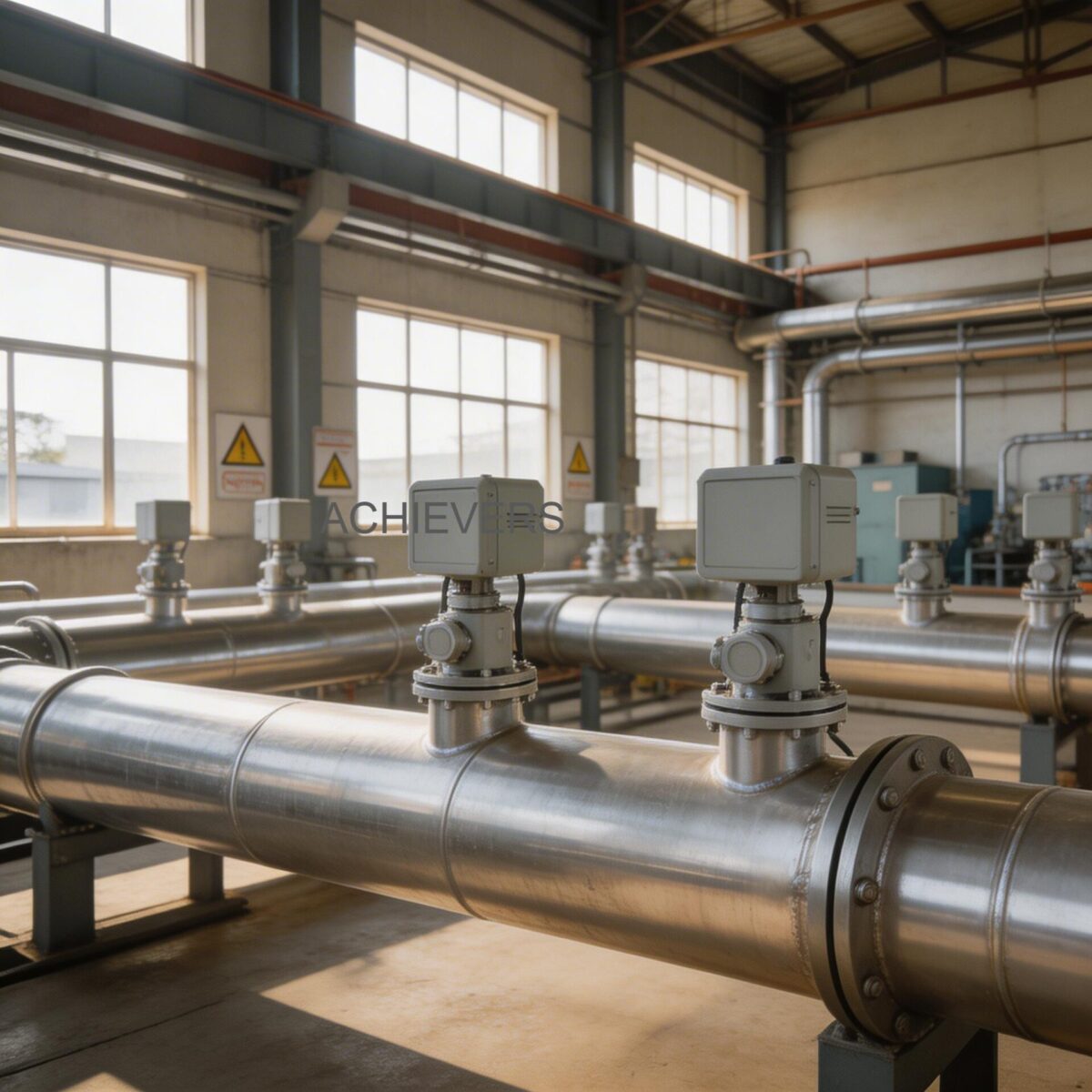
Field Installation Procedure (Clamp-On/Sandwich & Flange Types)
Improper installation is the leading cause of vortex meter failure in Indian industries. Follow this strict instrumentation procedure:
- Verify Line Size and Reynolds Number: Do not automatically buy a meter to match your pipe size. If your flow velocity is low, you may need to reduce the pipe size at the meter location to increase velocity and ensure Re > 20,000.
- Ensure Straight Pipe Runs: Measure and mark at least 15 to 20 pipe diameters of straight, unobstructed pipe upstream of the installation point, and 5 pipe diameters downstream.
- Align Flanges and Gaskets: When inserting a sandwich/wafer type meter between flanges, ensure the gaskets are perfectly centered. A protruding gasket acts as a secondary bluff body, completely destroying measurement accuracy.
- Observe Flow Direction: Install the meter matching the engraved flow direction arrow on the transmitter body. Vortex meters are strictly unidirectional.
- Bolt Torquing: Tighten the flange bolts in a star/criss-cross pattern. Uneven torque can distort the meter body and exert stress on the piezoelectric crystals, leading to baseline drift.
- Electrical Termination & Grounding: Connect the 24Vdc two-wire loop. In Indian plants prone to heavy electrical noise, ensure the meter body is bonded to a high-quality earth ground to prevent electromagnetic interference from affecting the micro-volt sensor signals.
- DCS Configuration: Input the meter's K-factor (pulses per unit volume) into your flow computer or DCS, and verify that the low-flow cutoff filter is correctly set to ignore ambient pipe vibrations when the flow is zero.
6. Calibration, Verification, and Certification
Industrial accuracy requires rigorous calibration. Vortex meters are factory-calibrated on specialized water or air flow rigs. The primary output of this calibration is the K-factor, which represents the number of pulses generated per unit volume of fluid (e.g., pulses per liter).
Because the Strouhal number is defined by the rigid geometry of the stainless steel bluff body, the K-factor is incredibly stable over time. Unlike moving-part meters, the K-factor of a vortex meter will only shift if the bluff body is physically damaged, eroded, or heavily coated with scale.
Field Verification:
For Indian facilities bound by ISO 9001 audits, complete removal for wet-calibration every year is often impractical. Instead, field verification focuses on the electronics. Instrumentation engineers can use a frequency generator to inject a simulated vortex frequency into the transmitter, verifying that the 4-20 mA output perfectly tracks the simulated flow. Additionally, the capacitance of the piezoelectric sensor can be checked with a multimeter to ensure crystal integrity.
For critical steam applications in India, installations must often comply with the Indian Boiler Regulations (IBR), requiring certified high-tensile fasteners and specific flange ratings. For petrochemical applications, ensure the housing carries the appropriate PESO (Petroleum and Explosives Safety Organisation) flameproof certifications.
FAQ
Q: Why does my vortex meter read zero even when there is a small amount of flow in the pipe?
A: This is due to the "low-flow cutoff." At low velocities, the Reynolds number drops below 20,000, and the fluid fails to generate stable vortices. The meter is programmed to read zero to prevent false readings from ambient pipe vibration.
Q: Can I use this technology for highly viscous liquids like crude oil or syrup?
A: No. High viscosity prevents the turbulent flow necessary for von Kármán vortex shedding. For heavy fluids, you should utilize Positive Displacement meters.
Q: Is it suitable for saturated steam at 200°C?
A: Yes, absolutely. The meters handle up to 350°C and 20 kg/cm². Ensure you select a model with inbuilt pressure and temperature compensation to calculate true mass flow as steam density changes.
Q: What causes the meter to show flow when the pipeline valves are completely closed?
A: This is called "ghost flow," caused by structural vibrations (from nearby pumps or machinery) shaking the pipe at a frequency similar to vortex shedding. You must increase the noise floor filter or adjust the DSP settings in the transmitter.
Q: How does hard borewell water, common in India, affect the meter?
A: Heavy calcium or magnesium scaling will physically coat the bluff body. This changes the structural width (d) in the Strouhal formula, altering the shedding frequency and causing measurement errors. Periodic chemical cleaning is required.
Q: Can the meter output mass flow directly to my DCS?
A: Yes. Because Lumen Instruments offers models with inbuilt pressure and temperature compensation, the internal microprocessor continuously calculates fluid density and can output a direct mass flow reading via 4-20mA or RS485 Modbus.
Q: How frequently does the instrument require recalibration?
A: Because there are no moving parts to wear out, wet recalibration is typically only needed every 2 to 3 years, provided the bluff body is not eroded. Annual electronic verification of the sensor and transmitter is recommended.
Selecting the exact specifications for your fluid dynamics requires careful engineering review. To get a precise technical evaluation and pricing for your specific site conditions—including correct line sizing to ensure optimal Reynolds numbers—contact us today with your process fluid, required flow rates, pipe size, and operating temperature/pressure.