
In the high-stakes environment of Indian industrial manufacturing, power generation, and petrochemical processing, accurate flow measurement is non-negotiable. Whether you are managing custody transfer of diesel at ₹90+ per liter, monitoring boiler feed water, or dosing solvents in a pharma plant, a flow measurement failure directly impacts the bottom line. For equipment investments ranging from ₹20,000 to over ₹10,00,000, instrumentation engineers cannot afford to rely on guesswork when a batching system goes blind.
When Turbine Flow Meters experience signal dropouts, intermittent RS485 communication, or a complete loss of pulse output, the root cause could be mechanical, electrical, or hydrodynamic. Given the harsh realities of Indian site conditions—ranging from severe voltage fluctuations and poor earth grounding to monsoon humidity, high ambient temperatures, and contaminated diesel—diagnosing these issues requires a systematic engineering approach.
This guide provides a comprehensive, step-by-step diagnostic workflow to isolate whether your pulse or RS485 data issues originate from the pickoff sensor, wiring infrastructure, electrical noise, or actual flow conditions affecting rotor velocity.
1. Quick Reference: How Turbine Flow Meters Work
Before diving into diagnostics, it is critical to understand the operating principle and the electromechanical handshake occurring inside the meter. The operation of Turbine Flow Meters is based on measuring the velocity of oil, heavy oil, furnace oil, water, and non-acidic liquids.
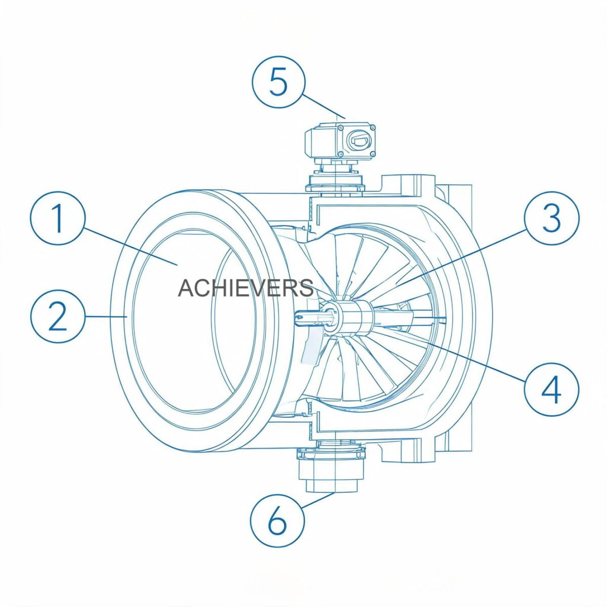
- Flow Conditioning: The flowing liquid is first accelerated and conditioned by the meter's straightening section. Straightening vanes remove undesired swirl, turbulence, and asymmetry before the fluid reaches the turbine wheel.
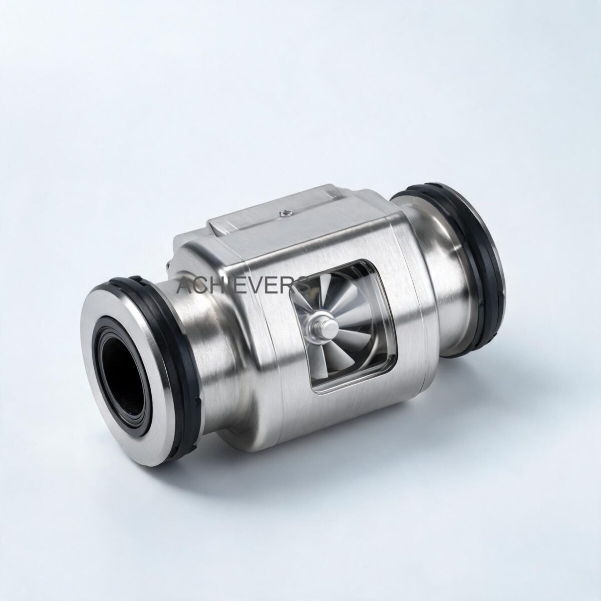
- Rotor Dynamics: The dynamic forces of the flowing fluid cause the rotor (typically S.S-304 or S.S-316) to rotate. The turbine wheel is mounted on a hard Stainless Steel-316 main shaft equipped with a precision carbon bush for low friction.
- Angular Velocity: The helical blades are set at a known angle relative to the fluid flow. The conditioned liquid drives the wheel with an angular velocity strictly proportional to the fluid velocity.
- Signal Generation: A proximity probe (magnetic pickoff sensor) generates a signal at each passing blade. As the stainless steel blades cut through the magnetic field of the sensor, an AC voltage or direct pulse is induced.
- Electronic Output: The meter generates pulses via an NPN open connector. The measured frequency is used to calculate the instantaneous flow rate, while accumulated pulses determine totalized volume based on the meter's specific K-factor.
Calibration Note & Engineering Formula
The fundamental relationship governing the meter's output is defined by its K-factor (pulses per unit volume).
Frequency (Hz) = (K-factor * Flow Rate in L/min) / 60
If your batch controller expects 100 pulses per liter and the meter is delivering 95, you will experience a 5% volumetric error. During troubleshooting, verifying the raw frequency output against the expected K-factor is often step one.
Technology Comparison Table
No single technology fits every application. When diagnosing chronic failures, engineers must verify if the right technology was selected for the fluid and site conditions.
| Parameter | Turbine Flow Meter | Electromagnetic Flow Meter | Positive Displacement (PD) | Vortex Flow Meter |
| — | — | — | — | — |
| Operating Principle | Kinetic / Velocity | Faraday's Law of Induction | Volumetric Trapping | Karman Vortex Street |
| Best Used For | Clean, low-viscosity liquids (diesel, water) | Conductive liquids (water, slurries) | High viscosity oils, fuels | Steam, gases, clean liquids |
| Standard Accuracy | +/- 0.5% to 1% FSD | +/- 0.5% | +/- 0.1% to 0.5% | +/- 1% |
| Pressure Drop | Moderate (increases with flow) | Zero (unobstructed tube) | High (due to tight clearances) | Moderate (bluff body) |
| Viscosity Limit | Low to Medium | Unaffected | Excellent for High Viscosity | Low |
| Susceptibility to Dirt | High (Requires upstream strainer) | Low | High (Will jam if unfiltered) | Moderate |
When to Use This Technology (Decision Matrix)
- CHOOSE Turbine when you need cost-effective, high-accuracy (+/- 0.5% or 1% FSD) measurement of clean, low-viscosity fluids like diesel, light oils, or RO water. They offer excellent repeatability (0.1%) and handle high pressures (up to 6 Mpa) and wide temperature ranges (-20 to 120 °C).
- AVOID Turbine if the fluid contains heavy particulates, fibers, or high viscosity variations. If your application involves conductive raw water with high suspended solids, Electromagnetic Flow Meters are the technically superior choice.
2. Troubleshooting Matrix
When a Turbine Flow Meters installation fails in an Indian industrial plant, the symptoms often overlap. Use the following diagnostic matrix to narrow down the root cause before dismantling the pipework.
| Symptom | Likely Cause | Diagnosis Steps | Fix |
| — | — | — | — |
| Zero Pulse Output | No power or severed cable | Check 12V DC power supply at sensor terminals. | Repair wiring or restore 12V supply. |
| Zero Reading (Local LCD) | Dead battery or jammed rotor | Check 3.3V lithium battery voltage. If good, inspect rotor. | Replace 3.3V 10AH battery. Clear rotor debris. |
| Erratic/Jumping Flow Rate | Ground loop or EMI noise | Measure AC voltage on DC ground. Check for nearby VFDs. | Shield cables, separate instrument cable from power cables. |
| Intermittent RS485 Data | Missing Modbus termination / bad polarity | Verify A(+) and B(-) wiring. Measure 120-ohm termination. | Swap A/B if reversed. Install 120-ohm resistor at line ends. |
| Signal Dropouts at High Flow | Sensor gap too wide / Cavitation | Check proximity sensor seating. Check downstream pressure. | Adjust sensor gap. Increase downstream backpressure. |
| Over-registering Totalizer | Pipe vibration triggering false pulses | Turn off flow, monitor pulse output. Check for pump vibration. | Isolate meter with flexible joints or improve pipe supports. |
| Under-registering Totalizer | Viscosity increase / Worn carbon bush | Verify fluid temperature. Inspect shaft/bush for mechanical wear. | Heat fluid to lower viscosity. Replace worn carbon bush. |
| High Pitched Noise / Whine | Bearing failure from overspeeding | Check flow rate against max capacity of the specific model. | Replace internals. Install flow restrictor to prevent overspeed. |
| Output Signal Stuck High | NPN circuit failure / Short to power | Measure NPN output state. Should alternate >8VDC and <0.8VDC. | Replace the pulse output sensor module. |
| 4-20mA Signal Drift | Loop resistance too high / Poor 24V supply | Measure loop resistance. Check 24V DC supply under load. | Upgrade power supply. Ensure loop resistance is < 600 ohms. |
3. Step-by-Step Field Diagnosis Procedure
When your control room reports a loss of flow indication, deploying an engineer with a multimeter and this 8-step field procedure is the fastest way to restore operation.
Required Tools: True-RMS Digital Multimeter, oscilloscope (optional but recommended for RS485), standard hand tools, Modbus polling software (like Modbus Poll on a laptop), and a portable frequency generator.
- Verify the Power Supply Under Load:
- For pulse output sensors, verify exactly 12 V DC at the meter terminals. Indian industrial grids frequently suffer from voltage dips; a supply dropping to 9V under load will cause the sensor circuitry to fail.
- For 4-20mA variants, verify 24 V DC.
- For battery-operated models, confirm the dual row LCD is active. The 3.3V 10AH lithium battery should last over 5 years, but extreme heat (>50°C ambient) can degrade it faster. Note: Total flow values for ten years are saved in non-volatile memory during power loss.
- Validate NPN Open Connector Logic States:
- Disconnect the output wire from the PLC. Hook a multimeter between the signal wire and ground.
- Manually spin the rotor (if safe to remove) or allow slow flow.
- The specification dictates a high electric level > 8 VDC and a low electric level < 0.8 VDC (based on a 12 VDC input). If the voltage hovers at 5V or doesn't drop below 0.8V, the NPN transistor is damaged or improperly pulled up at the PLC.
- Perform RS485 Communication Health Check:
- Measure the DC voltage across the A and B terminals. It should idle around 200mV to 5V depending on the bias.
- If using Modbus RTU, ensure the baud rate, parity, and slave ID match the DCS settings.
- Check for a 120-ohm termination resistor at the far end of the RS485 daisy chain to prevent signal reflections, which cause intermittent data dropouts.
- Test for Ground Loops and EMI:
- Measure AC voltage between the instrument ground and the plant earth. Anything above 1-2 VAC indicates a ground loop.
- Indian plants frequently lack isolated clean earths. Ensure the shielded cable is grounded at ONE end only (typically at the control panel) to prevent circulating currents that mask the low-amplitude pickoff signal.
- Inspect the Magnetic Pickoff Sensor Assembly:
- Unscrew the pickoff sensor from the S.S-304/S.S-316 enclosure. Check for moisture ingress or physical damage to the probe tip.
- Verify the internal resistance of the coil (typically a few hundred ohms). An open circuit means the sensor must be replaced.
- Evaluate Flow Profile and Straight Piping Requirements:
- Turbine meters require a fully developed velocity profile. Verify there is a minimum of 10 pipe diameters (10D) of straight run upstream and 5D downstream.
- If installed immediately after a 90-degree elbow or a control valve, the resulting swirl will cause erratic pulse generation.
- Mechanical Inspection of Rotor and Bearings:
- Isolate the line, depressurize, and remove the meter.
- Inspect the S.S-304 / S.S-316 rotor. Check for broken helical blades or foreign debris wrapped around the shaft.
- Spin the rotor by hand. It should spin freely and coast to a smooth stop. A sudden stop indicates a worn carbon bush or damaged hard stainless steel shaft.
- Verify Process Fluid Limits:
- Ensure the temperature is within the -20 to 120 °C rating.
- Check actual line pressure against the 6 Mpa maximum working pressure.
- Verify the flow rate aligns with the meter's model sizing. For example, a CE-TFS-050 (50mm) is calibrated for 4,000~40,000 L/H. Operating below 4,000 L/H will result in severe pulse dropouts due to insufficient kinetic energy to overcome bearing friction.
4. Installation and Setup Errors That Cause Ongoing Problems
Even the most robust instruments will fail continuously if installed against engineering best practices. The following table highlights common installation errors seen in the Indian market and their necessary corrections.
| Installation Error | Symptom Observed | Engineering Correction |
| — | — | — |
| No Upstream Strainer Installed | Jammed rotor, sudden loss of pulse, zero flow | Install a Y-strainer (e.g., 60-100 mesh) upstream to catch welding slag and scale. |
| VFD Power Cables Routed with RS485 | Erratic flow readings, false pulses totalizing | Separate signal cables from power cables by at least 300mm. Use dedicated steel conduits. |
| Meter Installed at High Point of Pipe | Signal dropouts, meter reads high due to air | Relocate to a lower section or vertical upward flow to ensure the pipe remains 100% full. |
| Control Valve Placed Upstream | Highly erratic reading, cavitation noise | Always install control valves downstream of the meter to maintain backpressure. |
| Insufficient Straight Run (e.g., 2D upstream) | Poor accuracy, fails to meet +/- 0.5% spec | Install flow straighteners/vanes or re-pipe to achieve 10D upstream / 5D downstream. |
| Pulsating Flow from Transfer Pumps | Non-linear pulse generation, premature bearing wear | Install pulsation dampeners or use Diesel Transfer Pumps with smoother output profiles. |
5. Preventive Maintenance to Avoid Recurrence
A reactive approach to instrumentation leads to unacceptable downtime. Implementing a scheduled maintenance regimen extends the lifespan of the carbon bush bearings and ensures the S.S-316 rotor maintains its precise helical geometry.
- Weekly: Monitor the dual-row LCD for any error codes. Check instantaneous flow (m3/h or L/h) against pump curves to verify basic sanity.
- Monthly: Blow down or clean the upstream Y-strainer. Contaminated diesel in transport applications is the number one cause of rotor jamming.
- Bi-Annually: Inspect the electrical enclosure for moisture ingress, especially post-monsoon. Re-tighten M/F thread or flange connections to prevent micro-leaks.
- Annually: Perform a master meter calibration check. Remove the meter, inspect the hard stainless steel shaft for scoring, and verify the carbon bush tolerances.
- Every 5 Years: Proactively replace the 3.3 V 10AH lithium battery in remote, standalone installations.

6. When to Call Service vs. Fix Yourself
Knowing when to escalate an issue saves time and prevents irreversible damage to precision instruments.
Fix Yourself:
- Wiring faults, blown fuses, or failed 12V/24V power supplies.
- Replacing the external magnetic pulse output sensor.
- Replacing the 3.3V lithium battery.
- Cleaning the upstream strainer or removing soft debris from the S.S rotor.
- Correcting Modbus RS485 addresses, baud rates, or adding 120-ohm terminating resistors.
Call Factory Service / Return to Manufacturer:
- The S.S-316 rotor blades are bent, chipped, or physically damaged.
- The internal carbon bush bearing is worn, causing the rotor to wobble.
- The meter requires recalibration and a new K-factor certification for Legal Metrology compliance or PESO documentation.
- The internal straightening vanes are damaged due to a severe hydraulic shock or water hammer.
FAQ
Q: Why does my flow totalizer keep increasing even when the pump is turned off?
A: This is known as "ghost pulsing." It is usually caused by unshielded signal cables picking up electromagnetic interference (EMI) from nearby variable frequency drives (VFDs) or severe pipe vibration mechanically shaking the pickoff sensor. Ensure the cable shield is grounded at one end only.
Q: How do I calculate the K-factor if the original calibration certificate is lost?
A: You cannot accurately calculate it mathematically due to manufacturing tolerances. You must perform a volumetric calibration by running a known volume of fluid (e.g., exactly 1,000 liters verified by a calibrated tank or weigh scale) through the meter, counting the raw pulses, and dividing total pulses by the total volume.
Q: Will a turbine meter work for highly viscous fluids like furnace oil?
A: It depends on the operating temperature. At high temperatures (up to 120 °C) where furnace oil viscosity drops significantly, it can work. However, if the oil cools and thickens, the increased drag will cause the rotor to under-register or stall completely. For high viscosity, Positive Displacement meters are preferred.
Q: What is the maximum distance I can run the RS485 communication cable?
A: Under ideal conditions with high-quality shielded twisted-pair cable (like Belden 9841) and proper 120-ohm termination, RS485 can reliably transmit data up to 1,200 meters (4,000 feet).
Q: My PLC requires a PNP signal, but the meter outputs NPN. How do I fix this?
A: The meter utilizes an NPN open connector. You can use a simple pull-up resistor to convert the signal, or preferably, install a low-cost, high-speed optocoupler or signal converter relay in the panel to convert the NPN sinking signal into a PNP sourcing signal.
Q: Are these meters approved by the Legal Metrology Department of India for custody transfer?
A: For official custody transfer and commercial billing in India, meters must undergo specific model approval and stamping by the Legal Metrology Department. Verify with the manufacturer if the specific CE-TFS model being purchased holds current LMD certifications for your application.
Q: Why is my meter experiencing a high pressure drop?
A: Excessive pressure drop usually indicates that the flow rate exceeds the maximum rated capacity of the meter (e.g., pushing 50,000 L/H through a CE-TFS-050 rated for 40,000 L/H max), or the upstream strainer is severely clogged with debris.
To ensure you select the right measurement technology and avoid frustrating downtime, expert engineering sizing is essential. Contact us today with your specific fluid type, minimum/maximum flow rates, line size, and operating temperature. Our team will help you configure the perfect flow measurement solution tailored to your site's unique requirements.