
In Indian industrial operations, whether you are running a 1000 kVA DG set during a grid outage, managing continuous process boilers, or monitoring draw-offs from bulk storage, accurate fuel measurement is critical. Unrecorded consumption due to a failed flow meter register can quickly lead to inventory discrepancies running into lakhs of rupees. When mechanical registers stall, digits stick, or counters reset erratically, plant engineers need a definitive fault isolation path before deciding to replace expensive equipment.
This guide provides a comprehensive Oil Flow Meters troubleshooting framework. Rather than blindly swapping out a ₹20,000 to ₹60,000 device, identifying the root cause—be it a sheared magnetic coupling, bypassed strainer, or viscous drag—can restore your Oil Flow Meters to factory-level accuracy. We will cover the mechanical intricacies of positive displacement mechanisms, the impact of Indian site conditions (from monsoon humidity to particulate-laden adulterated fuel), and specific field-corrective actions to resolve totalizer problems.
1. Quick Reference: How Positive Displacement Oil Flow Meters Work
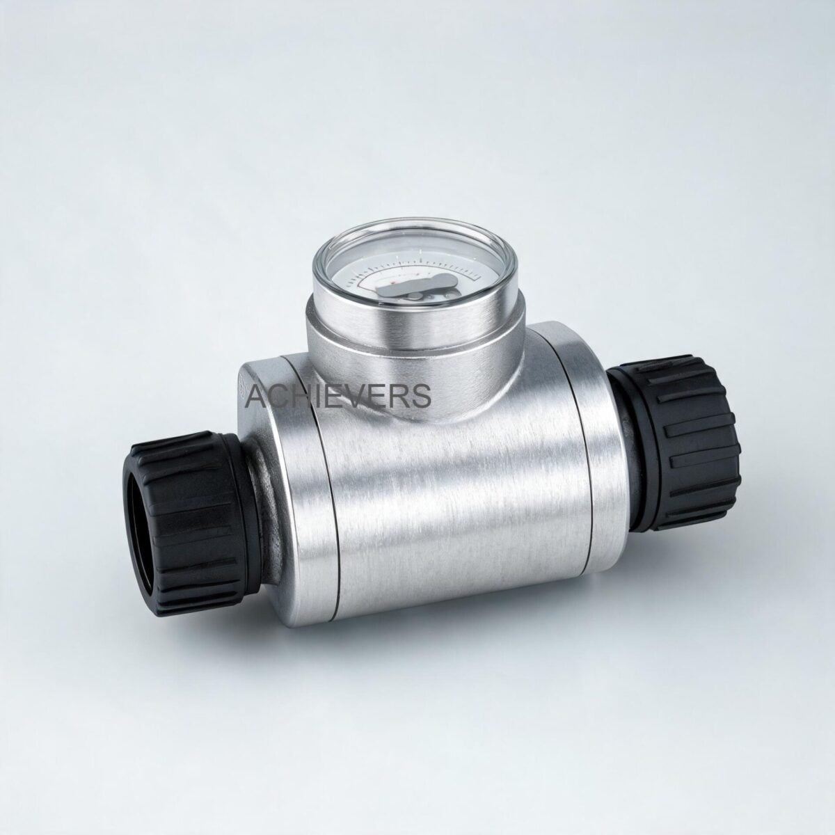
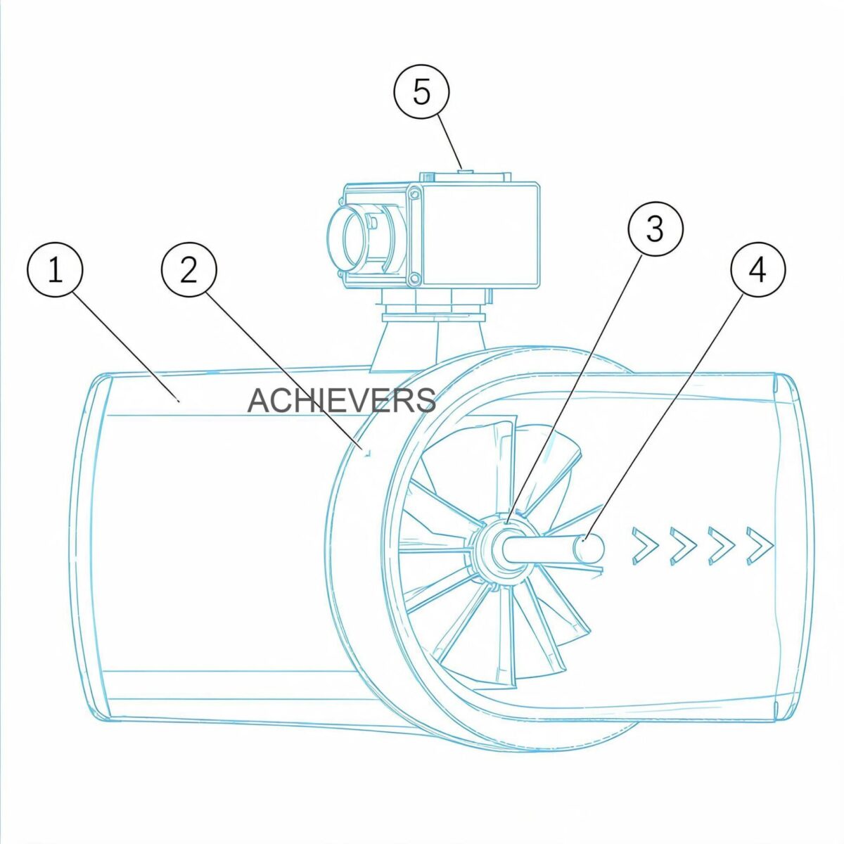
To troubleshoot a mechanical totalizer not working in oil flow meter causes and fixes, one must first understand the fluid mechanics and power transmission inside the meter. Our Oil Flow Meters operate on the Positive Displacement (PD) principle, specifically utilizing an oval gear or volumetric rotary cylinder design.
In a PD meter, the fluid itself provides the motive force. As diesel, LDO, or furnace oil enters the meter chamber, the pressure differential across the meter forces the internal gears or cylinders to rotate. Because the measuring chamber has a fixed, known volume, every single rotation correlates to an exact volume of displaced fluid.
The critical engineering feature in these Oil Flow Meters is the magnetic coupling. To prevent leaks, the wet side (measuring chamber) is completely sealed from the dry side (mechanical register). A drive magnet attached to the rotating gears magnetically engages a follower magnet connected to the totalizer's gear train. If the meter is flowing but the register is dead, the fault almost always lies in the breakdown of this magnetic transmission or the mechanical gear train itself.
Key Technical Specifications
Before diagnosing, verify that the meter is operating within its designed limits. Operating outside these parameters will cause mechanical binding.
| Specification Parameter | Technical Rating / Limit |
| :— | :— |
| Measuring Principle | Positive Displacement (Oval Gear / Rotary Cylinder) |
| Line Size Range | 006mm to 150mm (1/4 inch to 6 inch) |
| Standard Accuracy | +/- 0.5% of reading (Up to +/- 0.2% on request) |
| Repeatability | Better than 0.02% |
| Pressure Drop | Exceptionally low; operates under 1 inch gravity head of oil |
| Filtration Requirement | Minimum 100-mesh strainer upstream |
| Flange Standard | DIN ND10 (Screwed ends available for 15-25mm) |
2. Troubleshooting Matrix: Oil Flow Meter Totalizer Problem in India Industrial Plants
Use this comprehensive diagnostic matrix to isolate the root cause when your mechanical register behaves erratically.
| Symptom | Likely Cause | Diagnosis Steps | Field Fix / Correction |
| :— | :— | :— | :— |
| Totalizer completely dead (Fluid is flowing) | Decoupled or broken magnetic drive | Remove register head. Pass a strong magnet over the follower. If digits move, the internal drive magnet is jammed or demagnetized. | Replace magnetic coupling assembly. Ensure fluid temperature has not exceeded magnet's Curie point. |
| Digits sticking halfway (e.g., stuck between 9 and 0) | Gear train binding due to dust/humidity | Inspect mechanical register for ingress of moisture, rust, or Indian site dust. | Clean register gears with contact cleaner; replace if nylon gears are stripped. |
| Erratic or jumping counts | Air entrainment in fluid | Check for vortexing in storage tanks or suction side pump leaks. | Install an air release valve upstream of the meter. |
| Meter under-registering by >2% | Internal blow-by / rotor wear | Check fluid viscosity. High wear from particulate matter bypasses the 100-mesh strainer. | Inspect rotors for clearance tolerances. Replace rotors or entire measuring chamber. |
| Meter over-registering | Pipe vibrations simulating pulses | Check pipe supports. Mechanical vibration can cause the sensitive register to increment. | Isolate meter with flexible couplings or reinforce pipe supports. |
| Register turns backwards | Reverse flow | Check downstream check-valve (NRV) integrity during pump shutdown. | Install or repair the Non-Return Valve (NRV) downstream. |
| Totalizer stops intermittently | Debris stalling the oval gears | Isolate meter, open chamber, inspect for weld slag, rust, or contaminated fuel debris. | Clean chamber; flush pipeline. Clean the 100-mesh upstream strainer. |
| Pulse output lost (PG 1 models) | Loss of 12-24V power or sensor failure | Check voltage at PG 1 terminals with a multimeter. Check for open circuits in the 3-core cable. | Restore power supply. If power is good, replace the PG 1 pulse generator module. |
| High pressure drop (Pump cavitating) | Clogged strainer or high viscosity | Check differential pressure across the upstream strainer. | Clean the strainer basket. If fluid is Furnace Oil, check the heating/tracing system. |
| Reset knob fails to zero the batch | Reset clutch mechanism broken | Attempt manual reset. If it spins freely without engaging, the internal clutch spring is snapped. | Replace the mechanical register block. Avoid forcefully slamming the reset knob in the future. |
3. Step-by-Step Field Diagnosis Procedure
When conducting an oil flow meter repair and calibration service on-site, follow this logical, 8-step isolation procedure to safely diagnose a stalled mechanical totalizer without compromising line integrity.
Tools Required: Metric spanner set, hex keys, feeler gauges, digital multimeter (if electronic), bucket, and specialized cleaning solvent.
- Bypass the Flow: Engage the bypass loop valves to isolate the flow meter. Never attempt to open a meter under pipeline pressure. Drain the residual fluid from the meter casing into a safe container.
- Remove the Mechanical Register: Unbolt the register top (which can usually be rotated to 90º orientations). Lift it straight up to avoid bending the connecting pins.
- Test the Register Independently: Manually rotate the magnetic follower on the bottom of the register. If the mechanical digits turn smoothly, the register is healthy. The fault lies in the wet chamber.
- Check the Magnetic Coupling: Look at the drive magnet on the meter body. Ensure no fine ferrous particles (common in poorly filtered industrial tanks) have bridged the magnetic gap, causing a stall.
- Inspect the Upstream Strainer: Open the strainer housing. A positive displacement meter must have a minimum 100-mesh strainer. If the basket is ruptured or missing, debris has entered the measuring chamber.
- Open the Measuring Chamber: Carefully remove the front cover. Inspect the volumetric rotary cylinders or oval gears. Check for scoring marks on the chamber walls—a clear sign of particulate damage.
- Verify Clearances: Use a feeler gauge to check the clearance between the gears and the chamber wall. Excessive clearance causes "slip" (under-registration), while no clearance indicates thermal expansion or foreign matter jamming the gears.
- Reassemble and Conduct a Wet Test: Reassemble the gears ensuring the timing marks align perfectly. Reattach the register, open the isolation valves slowly to prevent pressure spikes (water hammer effect), and bleed all air from the system.
Engineering Calibration Note: Calculating the Meter Factor
After any repair, the meter must be proven against a known master volume. If you are experiencing positive displacement oil flow meter register sticking digits, repairing it may alter its calibration.
To calibrate, dispense a known volume (e.g., into a Legal Metrology certified 20-liter proving can).
Calculate the Meter Factor (MF):
Meter Factor = Actual True Volume / Meter Indicated Volume
If the meter reads 19.8 Liters but exactly 20.0 Liters was dispensed:
MF = 20.0 / 19.8 = 1.0101.
The internal step-less calibration mechanism can then be adjusted to bring the error within the +/- 0.5% specification.
4. Installation and Setup Errors That Cause Ongoing Problems
Many recurring failures are not manufacturing defects but installation errors. In the Indian market, where retrofitting is common and piping infrastructure may be decades old, correct installation geometry is paramount.
| Installation Error | Resulting Symptom | Engineering Correction |
| :— | :— | :— |
| No 100-Mesh Strainer Installed | Rotors jam repeatedly; severe internal scoring. | Always install a 100-mesh strainer upstream. For highly contaminated fuel, use a dual-stage filtration system. |
| Absence of Air Release System | Over-registration; erratic mechanical counting; air passes as liquid. | Install an air release valve at the highest point before the meter, especially critical in pump-unloading applications. |
| Piping Stress on Meter Flanges | Oval gears bind and stall due to casing distortion. | Ensure pipes are independently supported. The meter should not bear the weight of the piping network. |
| Incorrect Orientation | Totalizer is unreadable or magnetic coupling is misaligned. | Ensure rotor shafts are in the horizontal plane. Rotate the register top (increments of 90º) for readability, do not tilt the meter body. |
| Meter Oversizing | Meter fails to register low flows (e.g., idling generator). | Select meter based on flow rate, not pipe size. Use reducers. E.g., Use 15mm-25mm meters for monitoring boiler consumption. |
| Operating Below Minimum Head | Fluid bypasses meter without turning gears (stalling). | Ensure at least 1 inch of gravity head for unpumped systems, or switch to an 80mm size meter to reduce pressure drop. |
For applications handling aggressive chemicals rather than standard hydrocarbons, or if you require completely non-intrusive measurement without mechanical parts, you might explore alternative technologies like Positive Displacement Flow Meters for thicker resins, or electromagnetic meters for conductive fluids.
5. Technology Comparison & Decision Matrix
No single flow meter fits every application. When upgrading or replacing equipment, plant managers must evaluate if a mechanical positive displacement meter remains the best choice for their specific fluid and site conditions.
Technology Comparison Table
| Parameter | Positive Displacement (Oval Gear) | Turbine Flow Meters | Electromagnetic Flow Meters |
| :— | :— | :— | :— |
| Primary Application | High viscosity oils, Diesel, LDO, Furnace Oil | Low viscosity, clean liquids, water | Conductive liquids, water, slurries |
| Viscosity Dependency | Accuracy improves with higher viscosity | Accuracy degrades with high viscosity | Independent of viscosity |
| Straight Pipe Run Required | None (0D upstream / 0D downstream) | High (10D upstream / 5D downstream) | Moderate (5D upstream / 2D downstream) |
| Power Requirement | Zero (for mechanical registers) | Loop power / Battery required | 24V DC / 220V AC required |
| Pressure Drop | Moderate to Low (Operates on 1" head) | Moderate | Zero (Unobstructed flow path) |
| Filtration Needs | High (100-mesh strainer mandatory) | Moderate | Low |
| Typical Cost Range (INR) | ₹9,999 – ₹62,499 | ₹15,000 – ₹80,000 | ₹25,000 – ₹1,50,000+ |
'When to Use This Technology' Decision Matrix
- Choose Positive Displacement Oil Meters when: You are measuring non-conductive, viscous hydrocarbons (Diesel, LDO, Lubricants) in spaces with no straight pipe runs available, and you require a purely mechanical display that functions during power outages.
- Choose Turbine Flow Meters when: You have clean, low-viscosity fluids flowing at high velocities, and you have ample straight pipe runs to condition the flow profile.
- Choose Electromagnetic Meters when: You are measuring water, wastewater, or conductive chemicals where pressure drop is unacceptable and particulate matter is highly prevalent.
6. Preventive Maintenance to Avoid Recurrence
To ensure you don't continually need to buy oil flow meter with service support India, institute a robust preventive maintenance schedule. The harsh operating environments in Indian manufacturing, petrochemical, and construction sectors demand proactive care.
- Monthly Strainer Checks: The 100-mesh strainer is the primary defense. Check and clean it monthly. During monsoons, check storage tanks for water ingress, which causes rust that blinds the strainer.
- Register Greasing: The mechanical register top should be kept free of heavy dust. A light application of non-corrosive lubricant on the external reset mechanism prevents sticking.
- Calibration Verification: Under the Indian Legal Metrology Act, equipment used for custody transfer (like diesel dispensers) must be verified annually. Even for internal accounting, verify the step-less calibration system every 12 months using a certified prover tank.
- System Flushing: Before commissioning a new pipeline or after major pipe repairs, bypass the meter and flush the lines completely to remove welding slag and pipe tape.
7. When to Call Service vs. Fix Yourself
While this troubleshooting guide empowers plant engineers to handle routine faults, certain situations require specialized intervention.
Fix it Yourself:
- Cleaning upstream strainers and clearing pipeline blockages.
- Removing the mechanical register to check for magnetic decoupling.
- Reorienting the display head for better visibility.
- Installing an upstream air release valve to fix over-registration.
Call for Factory Service:
- The oval gears or rotary cylinders are deeply scored or chipped. (Requires precision machining or replacement of the measuring chamber).
- The step-less calibration system is maxed out, but the meter still fails to achieve +/- 0.5% accuracy.
- You require BIS or PESO certification compliance post-repair.
- Integration of BTF 200 Combined Batching, Totalizer, and Rate of Flow Units to automated PLCs via 4-20mA signals is failing due to board-level electronic issues.
*
FAQ
Q: Why does my flow meter totalizer reset to zero randomly during operation?
A: Random resetting is usually caused by heavy pipeline vibrations triggering a loose mechanical reset clutch inside the register. Ensure the meter is isolated from pump vibrations using flexible bellows and check the reset knob spring tension.
Q: Can I use this meter without a power supply?
A: Yes. The standard models are equipped with mechanical totalizers driven entirely by fluid pressure and magnetic coupling. They require zero electrical power, making them ideal for remote Indian mining or construction sites.
Q: How does the change in weather (monsoon vs. winter) affect accuracy?
A: High-viscosity fluids like Furnace Oil thicken in winters (especially in North India), which actually improves the volumetric efficiency (reduces slip) of positive displacement meters. However, if it thickens too much, it causes high pressure drop. Ensure tracing/heating keeps viscosity within operational limits.
Q: What is the purpose of the 100-mesh strainer?
A: Positive displacement meters have microscopic clearances between the gears and the chamber. The 100-mesh strainer traps rust, sand, and particulate matter that would otherwise score the chamber walls or jam the gears, causing a complete stall.
Q: My meter indicates flow when the pump is off. Why?
A: This is called "thermal expansion" or "gravity siphoning." If valves are left open and the fluid in the pipes heats up in the sun, it expands and pushes through the meter. Always install and close positive shut-off valves or a Non-Return Valve (NRV).
Q: Are these meters approved by Indian Legal Metrology?
A: Our meters can be provided with features that meet precision standards, but for commercial custody transfer (selling fuel to third parties), the specific installation must be tested and stamped by the local Legal Metrology inspector.
Q: Can I upgrade my mechanical meter to an electronic display later?
A: Yes. The modular design allows you to add a PG 1 Pulse Generator later. This converts the mechanical rotation into a pulse signal that can be sent to a TF 200 Remote Totalizer or your plant's SCADA system.
If you are experiencing persistent metering issues, or need to properly size a new installation to avoid these common pitfalls, contact our engineering team. Provide us with your target fluid, maximum/minimum flow rates, pipeline size, and specific site conditions, and we will configure a flow measurement solution built for absolute reliability.