
The cost of unplanned dispensing equipment failure extends far beyond the price of replacement hardware. In high-throughput industrial environments—whether mining operations in Western Australia, chemical plants in Germany, or heavy logistics depots—a malfunctioning dispensing nozzle can lead to fugitive emissions, severe safety hazards, inaccurate fluid inventory, and environmental non-compliance. Establishing a rigorous fuel nozzles preventive maintenance schedule for industrial diesel dispensing is critical to optimizing operational uptime and ensuring safety under stringent global standards like API RP 1604, ATEX, and ISO 14001.
This technical guide outlines a comprehensive preventive inspection protocol, seal replacement procedure, and shutoff verification methodology for industrial Fuel Nozzles. By standardizing maintenance practices, plant managers and reliability engineers can eliminate premature shutoff issues, prevent hazardous drips, and maintain precise flow measurement accuracy across their dispensing networks.
1. Product Overview and Critical Wear Components
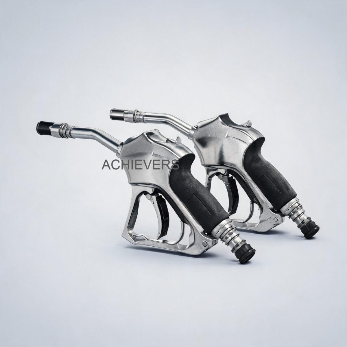
Industrial Fuel Nozzles operate using complex fluid dynamics and precision-machined mechanical components. At the core of the automatic shutoff mechanism is the Venturi effect. As fluid passes through the main poppet valve, it accelerates through a localized restriction, creating a pressure drop (vacuum). A sensing port at the tip of the 13/16" spout connects to this vacuum chamber via a continuous tube. As long as air is drawn through the spout tip, the vacuum is broken. When rising fluid in the receiving tank blocks the spout tip, the vacuum rapidly builds, pulling a sensitive diaphragm that trips the release latch, allowing the main spring to snap the poppet valve shut.
In advanced variants, such as digital metering nozzles, an integrated electronic or mechanical flow meter (typically utilizing a micro-turbine or oval gear mechanism) is housed within the nozzle body. This allows for dual-measurement and high-accuracy batch dispensing directly at the point of use.
Understanding the critical wear components of Fuel Nozzles is the first step in effective preventive maintenance:
- Main Poppet Valve and O-Rings: Subjected to constant dynamic friction and chemical exposure. Wear leads to post-shutoff dripping.
- Venturi Sensing Port & Tube: Susceptible to clogging from airborne dust, diesel particulate matter, or crystallized DEF (if misused). Clogs cause premature shutoff or total shutoff failure.
- Diaphragm Assembly: Flexible elastomeric component that degrades due to temperature fluctuations and chemical attack.
- Spout (13/16"): Experiences physical impact, bending stress, and abrasion from repeated insertion into tank fill necks.
- Inlet Swivel (BSP3/4"): High-stress articulation point that requires leak-free rotation under pressures up to 0.18 MPa.
Technology Comparison: Mechanical Shutoff vs. Digital Metering Nozzles
When upgrading dispensing infrastructure, engineers must select the appropriate nozzle technology based on process requirements.
| Specification / Parameter | Mechanical Automatic Shutoff Nozzles | Digital Metering Fuel Nozzles |
| :— | :— | :— |
| Primary Function | High-speed dispensing with safe shutoff | Dispensing with integrated volume tracking |
| Flow Rate Capability | 0 – 60 L/min | 0 – 60 L/min |
| Operating Pressure | 0.18 MPa (26.1 PSI) | 0.18 MPa (26.1 PSI) |
| Flow Measurement Accuracy | N/A (Relies on upstream Fuel Dispensers) | ± 0.5% to ± 1.0% (depending on viscosity) |
| Internal Mechanism | Venturi vacuum, mechanical diaphragm | Venturi vacuum + Turbine/Gear measurement |
| Power Requirement | None (Hydro-mechanical) | Internal Battery (AAA or Lithium for digital) |
| Weight Profile | Standard (approx. 0.8 – 1.0 kg) | Heavier (Net weight: 1.14 kgs/pc) |
| Ideal Application | Standard fleet refueling, rugged environments | Batch filling, decentralized inventory tracking |
Decision Matrix: When to Use Which Technology
- Use Mechanical Automatic Shutoff Nozzles When: The application is highly rugged, exposed to extreme physical abuse, or when high-accuracy custody transfer measurement is already being handled by upstream Diesel Flow Meters.
- Use Digital Metering Nozzles When: Dispensing into remote equipment (e.g., generators, heavy mining vehicles) where decentralized, localized volume tracking is required, or when batching specific quantities of motor oil, diesel, or gasoline into secondary containers.
2. Preventive Maintenance Schedule
A robust maintenance program shifts the operational paradigm from reactive repair to proactive reliability. Implementing a fuel nozzles inspection checklist for leakage and shutoff sensitivity is critical for maintaining the 0.18 MPa pressure integrity and 60 L/min flow efficiency.
Fluid Dynamics & Calibration Note
For Digital Metering Fuel Nozzles, the integrated flow meter must be periodically calibrated to ensure accuracy. The fundamental calibration error calculation used during maintenance checks is:
Percentage Error = ((V_indicated – V_actual) / V_actual) * 100
Where V_indicated is the volume shown on the digital display, and V_actual is the volume captured in a certified volumetric proving standard. If the error exceeds ±1.0%, the internal calibration factor (K-factor) must be electronically adjusted.
Comprehensive Maintenance Schedule
| Maintenance Task | Frequency | Responsible Personnel | Est. Time | Technical Notes & Specifications |
| :— | :— | :— | :— | :— |
| Visual Inspection of Spout & Body | Daily | Operator | 2 min | Check 13/16" spout for severe bends, cracks, or missing retention springs. |
| Verification of Free Rotation | Daily | Operator | 1 min | Ensure BSP3/4" inlet swivel rotates freely without binding to prevent hose torsion. |
| Sensing Port Clearance Check | Weekly | Maintenance Tech | 5 min | Ensure the vacuum port at the spout tip is free of mud, ice, or grease. |
| Leak-Down Test | Weekly | Maintenance Tech | 5 min | Pressurize to 0.18 MPa, release trigger. Verify zero dripping after 3 seconds. |
| Inline Strainer Cleaning | Monthly | Maintenance Tech | 15 min | Remove swivel, extract internal mesh strainer, clean with solvent and compressed air. |
| Flow Rate Verification | Monthly | Reliability Eng. | 10 min | Clock the dispensing rate into a prover. Must achieve near 60 L/min at optimal pump pressure. |
| Shutoff Sensitivity Test | Monthly | Reliability Eng. | 15 min | Simulate full tank block. Snap-action must occur in < 0.5 seconds upon port immersion. |
| Digital Display & Battery Check | Quarterly | Maintenance Tech | 10 min | Check for fading LCD digits on metering nozzles. Replace internal batteries as required. |
| Volumetric Calibration Check | Semi-Annually | Metrology Tech | 30 min | Use certified proving can to verify volumetric accuracy of the integrated digital meter. |
| Main Seal & Diaphragm Insp. | Annually | Maintenance Tech | 45 min | Full tear-down. Replace main poppet O-rings and inspect Venturi diaphragm for fatigue. |
3. Step-by-Step Procedures for Key Tasks
Industrial operations require strict adherence to standard operating procedures (SOPs). Below is the definitive industrial fuel nozzles seal replacement guide and preventive cleaning protocol.
Procedure 1: Strainer Cleaning and Flow Path Inspection
A clogged internal strainer creates a massive pressure drop, restricting the nozzle from achieving its 60 L/min specification and causing cavitation that can damage upstream pumps.
- De-energize and Isolate: Turn off the associated fuel pump and lock-out/tag-out (LOTO) the dispenser electronics.
- Depressurize the Line: Point the nozzle into an approved grounded safety container and squeeze the lever to relieve residual static pressure (0.18 MPa max).
- Disconnect the Swivel: Using two appropriately sized non-sparking wrenches, hold the nozzle inlet flat and loosen the BSP3/4" swivel connector.
- Extract the Strainer: Carefully remove the inlet swivel adapter to expose the internal mesh strainer located at the base of the handle. Use needle-nose pliers to gently pull the strainer cartridge out.
- Ultrasonic/Solvent Cleaning: Submerge the metallic strainer in a compatible solvent bath. If severe varnishing is present, utilize an ultrasonic cleaner for 5-10 minutes.
- Pneumatic Purging: Blow dry the strainer using low-pressure compressed air (max 30 PSI), directing airflow from the inside out to dislodge embedded particulate.
- Inspect Inlet O-Rings: Examine the FKM/Viton O-rings on the swivel mating surface. If flattened or cracked, discard and replace.
- Reassembly and Pressure Test: Reinsert the strainer, apply a small amount of petroleum-compatible thread sealant to the BSP3/4" threads (avoiding the first two threads), and torque the swivel to manufacturer specifications. Restore power and inspect for leaks under operating pressure.
Procedure 2: Main Seal Replacement and Shutoff Verification
When a nozzle fails the leak-down test (drips continuously after trigger release), the main poppet seal has failed.
- Preparation and LOTO: Isolate the pump, relieve line pressure into a safety can, and disconnect the nozzle completely from the dispensing hose. Move the nozzle to a clean, well-lit, static-free workbench.
- Remove the Spout Assembly: Loosen the retaining screws or retaining nut holding the 13/16" spout to the main aluminum body. Carefully pull the spout straight out to avoid damaging the internal vacuum tube.
- Extract the Poppet Valve: Remove the main top cap (usually secured by torx or hex bolts) covering the main spring and diaphragm assembly. Carefully lift out the heavy return spring and the poppet valve core.
- Replace the Main Seal: Using a brass or plastic pick, remove the primary elastomeric seal from the poppet groove. Clean the groove with a lint-free cloth. Lubricate the new manufacturer-specified O-ring with a light film of assembly lube and seat it firmly into the groove.
- Inspect the Diaphragm: Examine the automatic shutoff diaphragm beneath the poppet assembly. Look for pinhole leaks, edge tearing, or loss of elasticity. Replace if any degradation is observed.
- Reassemble Components: Reinstall the poppet valve, ensuring the sensing tube aligns correctly with the spout port. Seat the main spring and torque the top cap bolts in a cross-pattern to prevent housing warpage.
- Reattach Spout: Install the spout, ensuring the O-ring at the base of the spout is perfectly seated to maintain the critical vacuum seal.
- Shutoff Sensitivity Verification: Reattach the nozzle to the dispenser. Dispense fluid into a proving container at maximum flow (60 L/min). Suddenly submerge the tip of the spout into the fluid. The nozzle must immediately click off. If it continues to flow, the vacuum circuit is compromised, and the reassembly must be checked.
4. On-Site Spare Parts to Stock
To minimize downtime, procurement teams working with a trusted fuel nozzles supplier for manufacturers should maintain specific minimum and maximum inventory levels for consumable parts. Given the 1.14 kgs/pc build of these robust units, the internal soft parts are the primary consumables.
| Part Description | Material Type | Recommended Site Qty | Replacement Interval / Condition |
| :— | :— | :— | :— |
| Main Poppet Seal Kit | FKM / Viton | 1 per 3 active nozzles | Annually, or upon dripping |
| Spout Replacement Kit | Aluminum (13/16") | 1 per 5 active nozzles | When bent, crushed, or scored |
| Inlet Swivel O-Rings | Nitrile / FKM | 2 per active nozzle | Annually, or upon swivel leakage |
| Internal Mesh Strainer | Stainless Steel | 1 per 10 active nozzles | When physically torn or crushed |
| Replacement Diaphragm | Fabric-reinforced | 1 per 5 active nozzles | Every 2 years, or upon shutoff failure |
| AAA / Lithium Batteries | Electronic grade | 1 set per digital unit | Annually (for digital metering models) |
5. Diagnosing Maintenance-Related Failures
Effective troubleshooting requires understanding the interconnected pneumatic and hydraulic principles governing the nozzle.
| Failure Symptom | Missed Maintenance Task | Root Cause / Fluid Dynamic Result | Corrective Action required |
| :— | :— | :— | :— |
| Nozzle will not shut off | Weekly Sensing Port Check | Vacuum port at spout tip is clogged with debris; Venturi cannot pull vacuum. | Clear spout tip port with compressed air or fine wire. |
| Premature shutoff (clicks off constantly) | Monthly Strainer Cleaning | Flow restriction causing artificial vacuum, or damaged inner sensing tube. | Clean inlet strainer; check flow rate; replace spout if tube is crushed. |
| Drips continuously after trigger release | Annual Main Seal Insp. | Main poppet O-ring is scored by debris or chemically degraded. | Perform Procedure 2: Replace main poppet valve seal. |
| Flow rate severely restricted (< 30 L/min) | Monthly Strainer Cleaning | Debris blocking the BSP3/4" inlet mesh or upstream filter bypass. | Remove swivel and extract/clean internal strainer. |
| Leaking at the hose connection | Annual Swivel O-Ring Check | Torsional stress has worn the swivel O-rings flat. | Replace swivel O-rings; verify swivel rotates freely to prevent torsion. |
| Blank Digital Display / Inaccurate Output | Quarterly Battery/Cal Check | Dead battery or miscalibrated K-factor due to fluid viscosity change. | Replace internal batteries; perform volumetric proving and adjust K-factor. |

6. Extending Service Life in Global Operating Conditions
Industrial sites are unforgiving. For global facilities—from European automated transport depots to executing automatic shutoff fuel nozzles maintenance in India and across the extreme heat of the Middle East—the operating environment accelerates component wear.
Combating Extreme Temperatures:
In high ambient temperature zones, the elastomeric components (seals and diaphragms) are subjected to advanced thermal degradation. High temperatures also cause diesel and gasoline to expand, increasing static line pressure between the pump and the nozzle. Ensure that pressure relief valves on the dispensing lines are functioning so that static pressure does not exceed the nozzle's 0.18 MPa rating, which could blow out the main seal.
Managing High-Dust Environments:
In mining and construction applications, airborne particulate is the primary enemy of the Venturi vacuum system. Dust adheres to the residual fuel on the 13/16" spout, rapidly clogging the sensing port. Implement strict housekeeping protocols requiring operators to utilize protective nozzle boots or holsters that shield the spout from the environment when not actively dispensing.
Handling High-Throughput Vibration:
Continuous high-speed flow creates hydrodynamic vibration. Over time, this vibration can loosen the retaining screws on the spout and the top cap. Maintenance teams should incorporate a quarterly torque-check of all external fasteners into their preventive maintenance schedule to prevent structural fatigue.
By treating the fuel nozzle not as a disposable commodity, but as a highly engineered precision instrument, industrial operations can drastically reduce their total cost of ownership, eliminate environmental contamination risks, and maintain peak dispensing efficiency.
*
FAQ
Q: What is the maximum flow rate and operating pressure for these industrial digital fuel nozzles?
A: These nozzles are engineered to handle a maximum flow rate of 60 L/min with a maximum safe operating pressure of 0.18 MPa (approx. 26.1 PSI). Exceeding these limits can cause seal blowout and erratic shutoff behavior.
Q: Why does my automatic nozzle shut off continuously even when the tank is empty?
A: Constant premature shutoff is typically caused by a flow restriction creating an artificial vacuum in the Venturi. This is usually due to a clogged internal mesh strainer, a blocked sensing port on the spout tip, or a damaged/crushed internal sensing tube.
Q: Can these nozzles handle different types of fluids?
A: Yes, the mechanical and digital variants are compatible with diesel, gasoline, and motor oil. However, changing fluid viscosities (e.g., switching from diesel to motor oil) requires recalibrating the digital flow meter's K-factor to maintain accuracy.
Q: How often should the digital flow meter inside the nozzle be calibrated?
A: For industrial use, volumetric calibration checks against a certified proving standard should be performed semi-annually. In custody-transfer or high-precision batching environments, quarterly verification is recommended.
Q: My nozzle drips slightly after shutting off. Is this normal?
A: A drip of 1-2 drops immediately after snap-action is normal as the residual fluid in the spout drains. However, continuous dripping indicates a failure of the main poppet seal, requiring immediate lock-out and seal replacement to prevent hazardous spills.
Q: What thread standard does the nozzle use for connection?
A: The inlet features a BSP3/4" (British Standard Pipe) thread. It is critical to use compatible BSP fittings and appropriate thread sealants (avoiding PTFE tape that can shred and clog the poppet valve) during installation.
Q: Are replacement parts universal across all nozzle brands?
A: No. While outer dimensions like the 13/16" spout may be standard for certain vehicle fill necks, internal components like the diaphragm, poppet valves, and turbine mechanisms are proprietary. Always source exact manufacturer replacement kits to ensure functional safety and pressure integrity.
Ready to upgrade your dispensing infrastructure or establish a standardized preventive maintenance program? Contact our engineering team today to discuss Fuel Nozzles suited for your specific flow capacities, fluid dynamics, and unique site conditions, ensuring maximum reliability and measurement accuracy.