
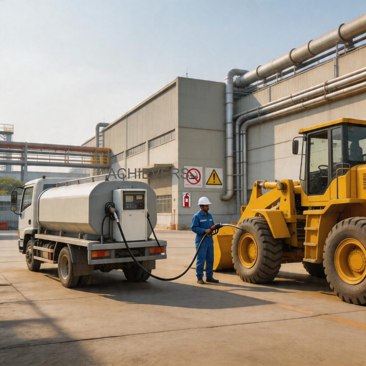
Accurate diesel fuel accounting is the cornerstone of profitable fleet and plant operations. For Indian industrial sites—ranging from remote mining excavations in Odisha to fast-paced logistics hubs in Gujarat—untracked fuel consumption translates directly to severe operational losses. When engineers and plant managers specify Mobile Fuel Dispensers for their facilities, they are not merely purchasing a pump; they are investing in a closed-loop metrology system designed to control pilferage and ensure absolute accountability for every liter of high-speed diesel (HSD) dispensed.
However, field accuracy is rarely as simple as reading the spec sheet. Indian site conditions introduce a host of variables: extreme ambient summer temperatures altering fluid kinematics, heavy particulate contamination in fuel, voltage fluctuations impacting pump RPM, and pulsation artifacts affecting the measurement element. Understanding the physical metering principles behind Mobile Fuel Dispensers—specifically how their internal flow meters handle these dynamic fluid conditions—is essential. This deep dive explores the engineering architecture of these units, the comparative physics of Positive Displacement (PD) versus Turbine metering, and how to maintain the critical ±0.5% precision limit across millions of liters of continuous service.
1. Working Principle: How Mobile Fuel Dispensers Operate
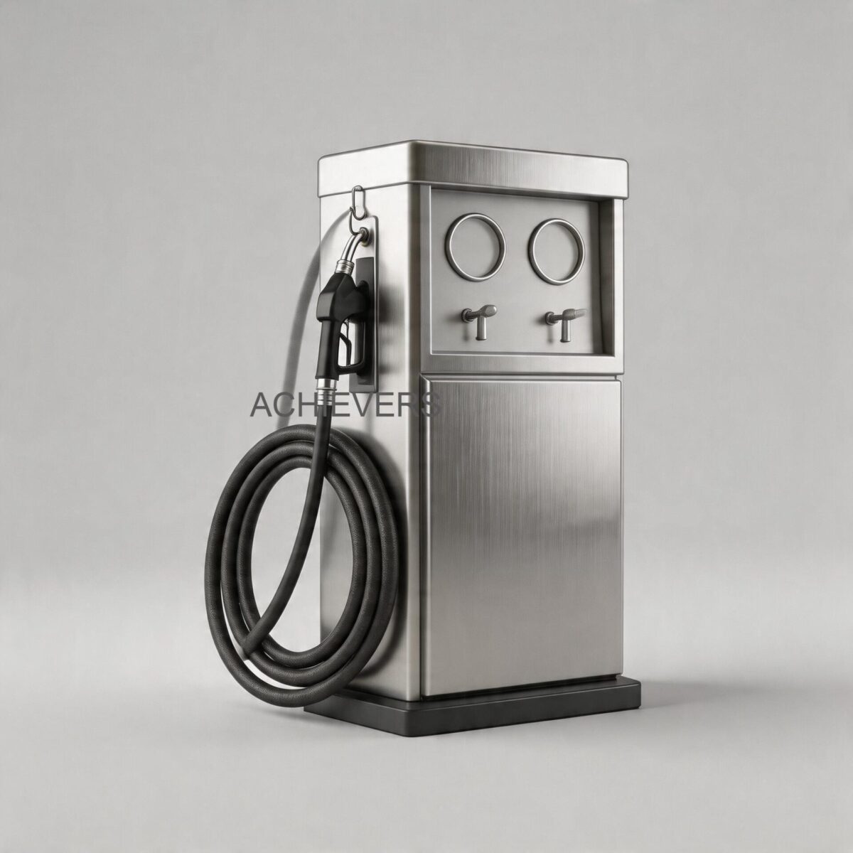
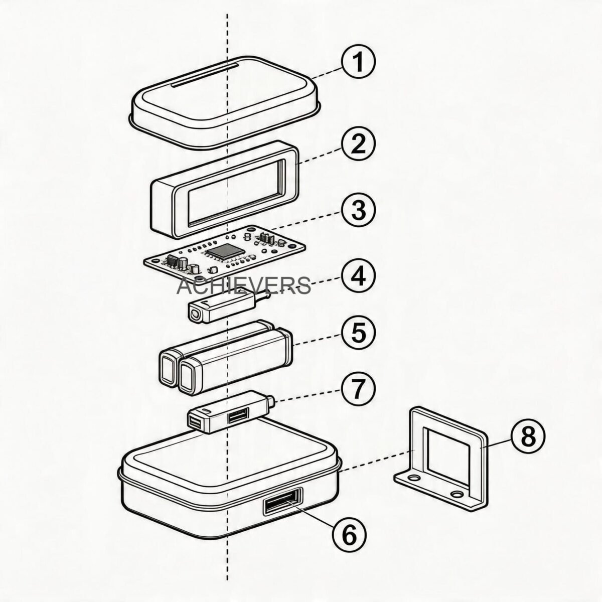
To understand the accuracy limits of Mobile Fuel Dispensers, we must dissect their internal flow path. These systems operate as an integrated skid consisting of a motorized prime mover, a self-priming vane pump, an air-elimination phase (if equipped), a high-precision flow meter, and a dispensing nozzle.
In premium models like the Achievers CE-117 and CE-204 series, the core measurement technology utilized is the Oval Gear Positive Displacement (PD) flow meter. Unlike velocity-based meters, positive displacement meters divide the fluid into discrete, known volumetric increments.
The Physics of Oval Gear Metering
When diesel enters the measuring chamber, the pressure differential across the meter forces two interlocking oval-shaped gears to rotate. Each rotation traps a precise, fixed volume of liquid in the crescent-shaped cavities between the gears and the outer housing.
The volumetric flow rate is governed by the engineering equation:
Q = 4 × V_c × N × η_v
Where:
Q = Total flow rate
V_c = Volume of a single measuring cavity
N = Rotational speed of the gears (RPM)
η_v = Volumetric efficiency (accounting for fluid slip)
Because the volume of the cavity is mechanically fixed by CNC-machined tolerances, the number of rotations is directly proportional to the volume of liquid passed. This rotation is transferred via a magnetic coupling or mechanical shaft to the digital or mechanical totalizer, registering the count (up to 9999999L on standard Achievers registers).
This PD mechanism is paired with a self-priming vane pump. Vane pumps are inherently capable of handling the suction lift required to pull diesel from underground or mobile storage tanks. A critical engineering synergy occurs here: the vane pump operates at 3 Bar of working pressure, providing enough head to overcome the pressure drop (ΔP) induced by the oval gears, ensuring smooth, continuous rotation without stalling the fluid column.
2. Complete Technical Specifications
Proper specification of a mobile dispensing unit requires aligning the pump and meter characteristics with the site's transfer requirements. The following specifications represent the standard engineered parameters for the Achievers mobile dispenser lineup (including CE-101, CE-117, CE-202, and CE-204 models).
| Parameter | Specification | Engineering Notes |
| :— | :— | :— |
| Applicable Media | High-Speed Diesel (HSD) | Kinematic viscosity optimized for 2 to 5 cSt |
| Measurement Element | Oval Gear Flow Meter | High-precision Positive Displacement (PD) technology |
| Volumetric Flow Rate | 60 Liters / Minute (LPM) | Optimized for truck and heavy equipment tank capacities |
| Working Pressure | 3 Bar (approx. 43.5 PSI) | Sufficient to maintain flow through filters and 4m hoses |
| Pump Prime Mover Power | 0.375 kW (375 Watts) | Low power draw, suitable for rural grid or generator power |
| System Precision | ±0.5% | Metrology-grade accuracy for reliable inventory reconciliation |
| Inlet / Outlet Ports | 25 mm (1 Inch) | Standardized for quick coupling and rigid piping |
| Batch Counter (One-time) | 0 – 9999 L | Resettable mechanical/digital register for single fill logging |
| Cumulative Totalizer | 0 – 9999999 L | Non-resettable auditing register for lifetime pilferage control |
| Dispensing Hardware | Metal Gun with Brass Fitting | Spark-resistant brass prevents accidental ignition |
| Hose Specification | 4 m Rubber Hose | Rated for continuous diesel exposure and high flexibility |
| Installation Mounting | Wall, Column, or Direct Tank | Quick coupling enabled for rapid site deployment |
3. Performance Characteristics and Error Sources
No measurement technology is immune to site conditions. In Indian industrial environments, accuracy drift is driven by three primary variables: fluid pulsation, temperature-induced viscosity shifts, and air entrainment.
Pump Pulsation Effects
Vane pumps provide a relatively smooth flow compared to diaphragm pumps, but minor hydraulic pulsations still exist. If a system utilizes a velocity-based meter, these pulsations can cause the rotor to over-spin due to inertia. However, because these mobile dispensers utilize Oval Gear Positive Displacement Flow Meters, the measurement is practically immune to flow profile distortions and pulsation. The gears only move when fluid mechanically forces them to, providing a tight 1:1 volumetric correlation regardless of upstream turbulence.
Viscosity and Temperature Extremes
In regions like Rajasthan or Central India, ambient temperatures can hit 45°C, causing diesel temperatures in above-ground tanks to rise significantly. As diesel heats up, its kinematic viscosity drops. In PD meters, lower viscosity can increase "fluid slip"—the tiny amount of liquid that escapes through the microscopic clearances between the gears and the housing without driving the gears. Fortunately, oval gear meters exhibit a very flat accuracy curve over diesel's typical viscosity range. The ±0.5% precision is maintained robustly, whereas a cheaper variable area meter would suffer massive calibration shifts.
Technology Comparison Table: Oval Gear (PD) vs. Turbine Metering
To understand why oval gear meters are the standard in these dispensers, we must compare them against the alternative: turbine metering.
| Evaluation Parameter | Oval Gear Flow Meter (Included) | Turbine Flow Meter (Alternative) |
| :— | :— | :— |
| Primary Measurement Principle | Positive Displacement (Volume) | Velocity-based (Speed of fluid) |
| Accuracy at Low Flow Rates | Excellent (Maintains ±0.5%) | Poor (Rotor stalls or under-registers) |
| Viscosity Immunity | High (Thicker fluids improve sealing) | Low (Calibration shifts with viscosity changes) |
| Upstream Piping Required | None (Immune to flow profile) | Minimum 10D straight pipe required |
| Pressure Drop (ΔP) | Moderate to High | Low |
| Susceptibility to Dirt | Moderate (Requires upstream strainer) | High (Bearings vulnerable to particulates) |
| Response to Pump Pulsation | Immune (Measures absolute volume) | Vulnerable (Over-run due to rotor inertia) |
'When to Use This Technology' Decision Matrix
Use this matrix to validate if an Oval Gear Mobile Dispenser is the correct architectural choice for your site:
- Choose Oval Gear Dispensers If:
- You are dispensing diesel or light oils (viscosities > 2 cSt).
- You require absolute accuracy (±0.5%) for financial accounting and inventory.
- Space is tight and you cannot install long, straight runs of pipe.
- The flow rate will vary frequently (e.g., operators partially squeezing the nozzle).
- Consider Turbine Flow Meters Only If:
- You are measuring ultra-low viscosity fluids like water or thin solvents.
- You have high flow rates (> 1000 LPM) where the pressure drop of a PD meter is unacceptable.
- Volumetric precision of ±1% to ±2% is acceptable for the application.
4. Materials and Chemical Compatibility
A flow measurement system is only as durable as its weakest wetted component. The standard mobile dispenser relies on a cast aluminum/cast iron pump body, hardened oval gears, brass nozzle fittings, and heavy-duty nitrile/Viton elastomers.
While optimized for high-speed diesel, operators often inquire about cross-compatibility. The table below outlines the suitability of the 60 L/Min mobile dispenser architecture for various industrial fluids.
| Industrial Fluid | Compatibility Status | Engineering Notes |
| :— | :— | :— |
| High-Speed Diesel (HSD) | Highly Compatible | Ideal lubricity and viscosity for oval gears. |
| Kerosene | Compatible | Lower viscosity, but within the ±0.5% measurement threshold. |
| Light Machine Oils | Compatible | Excellent lubricity. Flow rate may drop slightly due to higher viscosity. |
| Petrol / Gasoline | NOT Recommended | Low flash point requires specialized ATEX/PESO explosion-proof motors. |
| Bio-diesel (B20/B100) | Conditionally Compatible | Elastomers (seals/hoses) must be upgraded to Viton or Teflon. |
| Water / Hard Borewell Water | Incompatible | Lacks lubricity. Will cause rapid mechanical wear and rust in iron/steel parts. |
| DEF / AdBlue | Incompatible | Highly corrosive to brass nozzle fittings and standard cast bodies. |
| Heavy Fuel Oil (HFO) | Incompatible | Viscosity is too high for the 0.375 kW pump motor; will cause thermal overload. |
5. Calibration, Verification, and Certification
Maintaining the ±0.5% precision standard across months of heavy use in dusty, high-vibration Indian environments requires a strict metrology protocol. Dirt bypassing a compromised suction filter can wear the oval gears, marginally increasing the internal clearances and altering the calibration factor.
Indian industrial operations should comply with standards loosely mirrored by the Legal Metrology Act, which requires systematic proving of volumetric dispensing equipment. Verification should be conducted every 6 to 12 months using a certified volumetric proving measure (typically a 20-liter conical brass or stainless steel standard test measure).
7-Step Field Verification and Calibration Procedure
- Prepare the Proving Measure: Ensure the 20L volumetric proving can is clean, dent-free, and placed on a perfectly level surface near the dispenser.
- System Wetting: Dispense approximately 5 liters of diesel into the can to wet the internal surfaces, then drain it completely for the exact drip time specified on the proving can's certificate (usually 30 seconds). This eliminates "dry can" volume errors.
- Zero the Register: Reset the one-time batch counter on the dispenser's digital or mechanical register to exactly 0000L.
- Dispense at Operating Flow Rate: Open the metal nozzle completely and dispense diesel into the proving can until the fuel level reaches the zero mark on the gauge glass of the measure. Do not restrict the flow, as testing must simulate normal 60 L/Min operating conditions.
- Record and Compare: Read the exact volume indicated on the dispenser's register. If the register shows 20.10 Liters, the meter is over-registering (delivering less than it claims). If it shows 19.90 Liters, it is under-registering.
- Calculate the Error Percentage: Use the formula: Error % = [(Meter Reading – Actual Volume) / Actual Volume] × 100. If the error exceeds ±0.5%, mechanical calibration is required.
- Adjust the Calibration Mechanism: Access the bypass calibration screw or the digital K-factor setting (depending on the specific register model integrated). Adjust incrementally, re-run the 20L test, and repeat until the error is minimized below ±0.2%. Seal the calibration screw to prevent unauthorized tampering.
When deployed with rigorous installation standards—including dedicated 220V AC / 12V-24V DC stable power supplies, primary Y-strainers to catch particulate matter, and strict adherence to calibration schedules—these mobile units provide the metrological backbone required for total site fuel security.
FAQ
Q: Will voltage fluctuations from my site generator affect the meter's accuracy?
A: No. Voltage drops may reduce the RPM of the 0.375 kW motor, resulting in a slower flow rate (e.g., dropping from 60 LPM to 45 LPM). However, because the oval gear meter is a positive displacement device, it measures pure volume regardless of fluid velocity. Your dispensing time will increase, but the volumetric accuracy remains ±0.5%.
Q: Why does the system include a 4-meter rubber hose, and can I extend it to 15 meters?
A: The 4-meter hose is engineered to balance reach with the pressure drop capabilities of the 3 Bar pump. Extending the hose to 15 meters increases fluid friction significantly, which may cause the pump motor to strain and reduce the flow rate well below 60 LPM. If longer reaches are necessary, hose diameters must be increased to reduce pressure loss.
Q: Can this unit detect and separate water from the diesel?
A: The standard CE-series mobile dispenser is designed for volumetric metering and does not feature built-in water separation. For Indian sites suffering from monsoon water ingress in storage tanks, an external water-absorbing filter (hydro-filter) should be installed on the discharge side before the meter.
Q: How often should the internal oval gears be replaced?
A: Oval gears typically last for millions of liters if pumping clean diesel. The primary cause of premature wear is particulate matter. Provided the suction strainer is cleaned monthly and prevents grit from entering the chamber, the gears rarely need replacement within a 5-to-7-year operational lifecycle.
Q: Is the digital/mechanical totalizer tamper-proof to prevent fuel theft?
A: Yes, the cumulative totalizer (0-9999999L) is non-resettable. Even if the one-time batch counter is zeroed by an operator, the master totalizer continuously logs every drop passed, ensuring plant managers can reconcile the physical tank dips against the meter's lifetime record.
Q: Can we use this dispenser for high-viscosity gear oils or hydraulic fluids?
A: While the oval gear meter handles high viscosities exceptionally well, the 0.375 kW self-priming vane pump is not rated for heavy oils. Pumping heavy gear oil will result in severe flow restriction and potential thermal overload of the motor. You would need a dedicated gear pump system for those fluids.
Q: Do I need a straight pipe run before the meter like I do for vortex or magnetic meters?
A: No. A major engineering advantage of the positive displacement oval gear meter is its complete immunity to flow profile disturbances. It can be bolted directly after a 90-degree elbow or pump discharge without any straight pipe requirements, enabling the highly compact mobile form factor.
For specialized engineering assistance in selecting the correct metering technology, flow capacity, and power configuration for your unique industrial site, contact our technical team with your required flow rates, fluid characteristics, and operating conditions.