
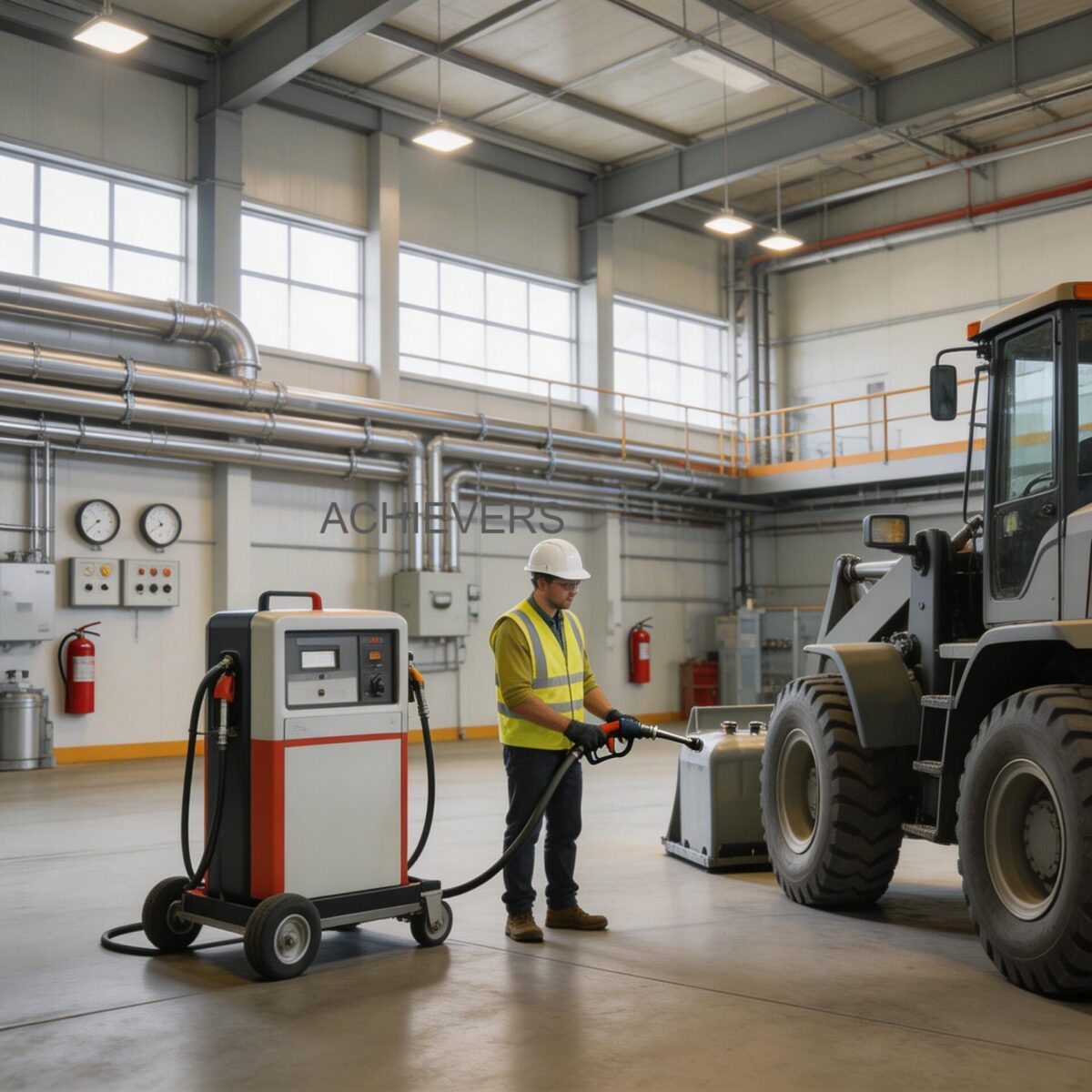
Deploying fueling infrastructure in remote, off-grid environments or across sprawling industrial sites requires measurement and transfer systems that are both highly ruggedized and meticulously engineered. While stationary fuel depots rely on massive, hard-piped infrastructure, field operations demand modularity without sacrificing metering integrity. This is where Mobile Diesel Dispensers bridge the gap between static bulk storage and the dynamic refueling needs of heavy machinery, mining fleets, agricultural equipment, and backup power generators. Understanding the internal architecture of these systems is critical for engineers tasked with controlling fuel shrinkage, maintaining fluid cleanliness, and ensuring accurate volumetric accounting.
A poorly specified dispensing system can lead to severe operational losses through meter drift, pump cavitation, or fluid contamination. By analyzing the engineering principles behind Mobile Diesel Dispensers, plant managers and procurement heads can evaluate equipment based on hydraulic performance, measurement accuracy, and component interaction rather than marketing claims. This technical deep-dive dissects the complete operational path of Mobile Diesel Dispensers—from the suction inlet and internal bypass mechanics to the positive displacement flow sensor and the fluid dynamics of the auto shut-off nozzle.
1. Working Principle: How Mobile Diesel Dispensers Operate
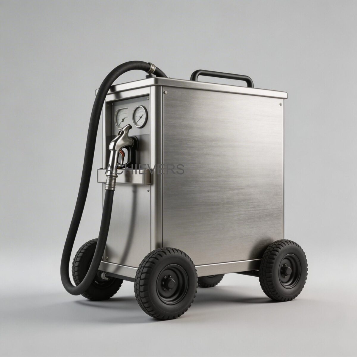
At its core, a mobile diesel dispenser is an integrated skid or wall-mountable unit comprising a prime mover (motor), a fluid transfer mechanism (pump), a precision measurement instrument (flow meter), and delivery accessories (hose and nozzle). The system operates as a cohesive hydraulic circuit designed to draw fuel from a storage vessel, pressurize it, measure it dynamically, and deliver it safely into a receiving tank.
The Hydraulic Path
When the motor is energized, the pump creates a localized pressure drop at the 25 mm inlet, inducing fluid flow from the primary tank. For typical diesel applications, the pump is either a rotary vane or a gear pump, capable of generating the required 3 Bar of working pressure. The fuel is pushed through an internal filtration screen to remove particulate matter that could otherwise score the metering chamber.
Once filtered, the pressurized fluid enters the measurement chamber. In high-accuracy mobile diesel dispensers, this is an Oval Gear Flow Meter, which is a specific type of Positive Displacement Flow Meters. The fluid pressure acts on the meshed oval gears, forcing them to rotate. Because the geometry of the measuring chamber and the gears is precisely machined, each rotation sweeps a discrete, fixed volume of fluid.
The Governing Volumetric Equation
The flow rate calculation in an oval gear meter is independent of fluid viscosity or flow profile, making it highly suitable for fluctuating field conditions. The total dispensed volume is determined by the formula:
V = N x v_s
Where:
- V = Total fluid volume dispensed
- N = Total number of gear revolutions
- v_s = Swept volume per single revolution (a constant physical parameter of the meter chamber)
The rotation of the gears is magnetically or mechanically coupled to a register, which translates the physical rotation into the visible 0-9999 L one-time batch count and the cumulative totalizer reading. Finally, the measured fuel travels through the 4-meter rubber hose and exits via the metal dispensing gun.
2. Complete Technical Specifications
Proper specification requires matching the dispenser's capabilities to the site's electrical infrastructure, required flow rates, and environmental conditions. The following table details the engineering specifications and component limits for standard mobile diesel dispensing units.
| Technical Parameter | Specification / Rating | Engineering Notes |
| :— | :— | :— |
| Applicable Media | Diesel / Bio-diesel | Calibrated for kinematic viscosities of 2 to 5.3 cSt at 40°C. |
| Measurement Technology | Oval Gear Flow Meter | High accuracy P.D. flow sensor; immune to flow profile distortions. |
| Volumetric Precision | ±0.5% | Factory calibrated; maintains accuracy across the turndown ratio. |
| Max Flow Rate Range | 60 LPM to 200 LPM | Varies by model (e.g., CE-101 vs. CE-130) and fluid viscosity. |
| Working Pressure | 3 Bar (approx. 43.5 PSI) | Sufficient for pushing through 4m hose and overcoming nozzle restriction. |
| Motor Power | 0.375 kW | Designed for continuous or specific duty cycles depending on model. |
| Power Supply Options | 12V DC, 24V DC, 220V AC | DC variants ideal for truck-mounting; AC for fixed industrial sites. |
| Inlet / Outlet Size | 25 mm (1 inch) | Standardized thread or quick coupling for rapid deployment. |
| Batch Totalizer Range | 0 – 9,999 Liters | Resettable mechanical or electronic display for single transaction tracking. |
| Cumulative Totalizer Range | 0 – 9,999,999 Liters | Non-resettable; used for long-term inventory auditing and shrinkage control. |
| Delivery Hose | 4 m Rubber Hose | High tensile strength; rated for maximum working pressure of the pump. |
| Nozzle Assembly | Metal Gun with Brass Fitting | Features an auto shut-off mechanism for tank topping up. |
| Model Variants | CE-101, CE-117, CE-130, CE-202, CE-204 | Rugged construction designed to suit harsh environmental conditions. |
3. Technology Comparison & Decision Matrix
Mobile diesel dispensing requires measurement technologies that can handle start-stop flows, vibration, and non-ideal piping runs. While oval gear meters are the standard for high-accuracy dispensers, engineers often evaluate them against turbine meters.
Technology Comparison Table: Oval Gear vs. Turbine Flow Meters
| Parameter | Oval Gear Flow Meter (P.D.) | Turbine Flow Meter |
| :— | :— | :— |
| Measurement Principle | Direct volumetric (Positive Displacement) | Inferential (Velocity-based) |
| Accuracy Rating | ±0.5% of reading | ±1.0% to ±2.0% of reading (in field conditions) |
| Viscosity Sensitivity | Improves sealing; highly accurate with viscous fluids | Accuracy drops significantly if viscosity fluctuates |
| Straight Pipe Requirement | 0D / 0D (None required) | 10D upstream / 5D downstream required for accuracy |
| Pressure Drop | Moderate to High (energy used to turn gears) | Low (minimal obstruction to flow) |
| Response to Start/Stop Flow | Excellent; captures every drop instantly | Poor; turbine freewheeling causes over-registration |
| Filtration Requirement | High; solid particles will jam the gears | Moderate; large debris can break rotor blades |
"When to Use This Technology" Decision Matrix
- Use Oval Gear P.D. Meters (Standard in Mobile Dispensers) When: You require custody-transfer level accuracy (±0.5%), the installation space is highly constrained (truck-mounted, no straight pipe runs), flow rates are frequently started and stopped, and fluid viscosity may vary slightly with temperature changes.
- Use Turbine Flow Meters When: You are measuring very low viscosity fluids (like water or light solvents), high pressure drops are unacceptable, high accuracy is not the primary concern, and you have ample space for straight pipe conditioning upstream of the meter.
- Use Electromagnetic Flow Meters When: You are dispensing conductive fluids (water, chemicals). Note: Electromagnetic meters cannot measure diesel fuel because hydrocarbons are non-conductive.
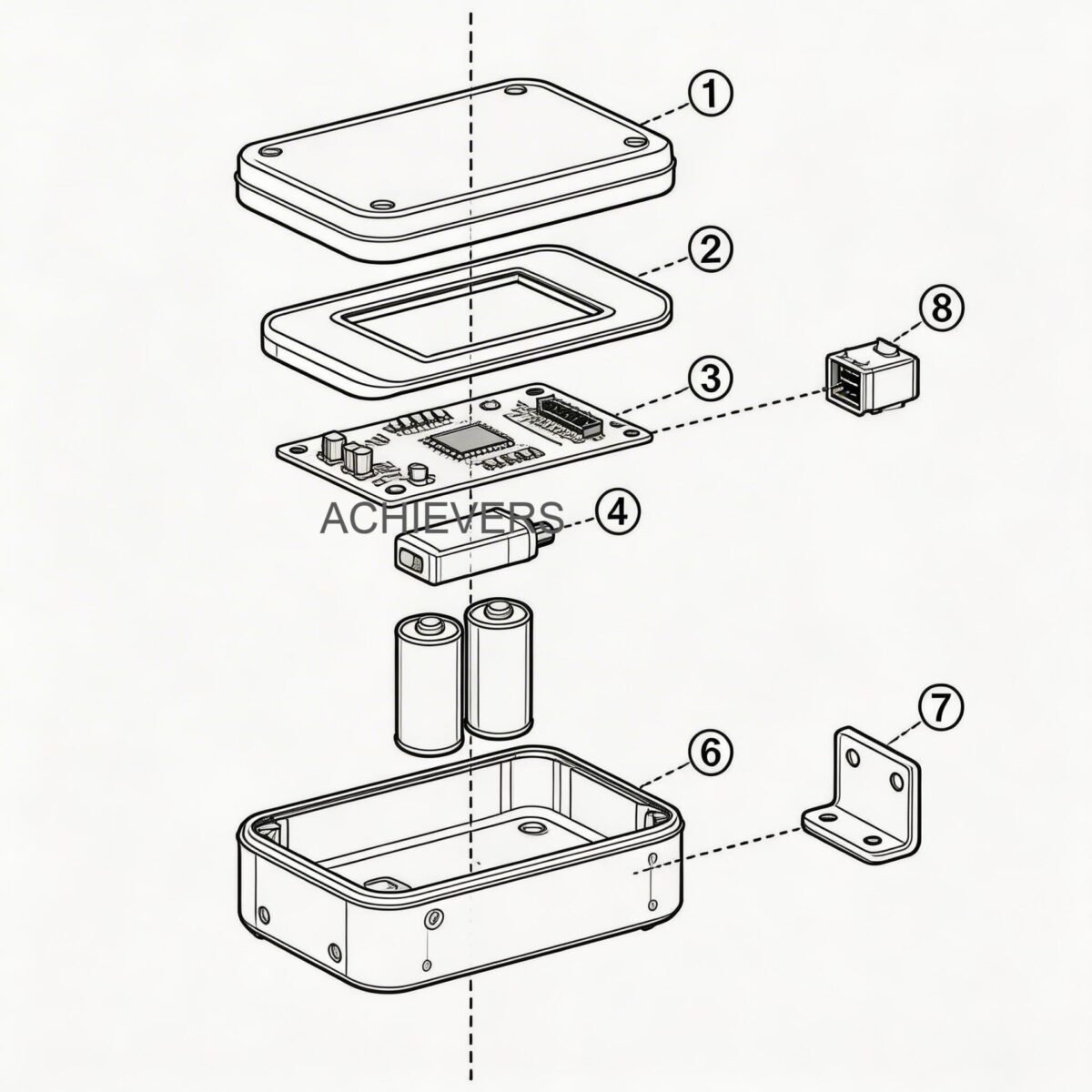
4. System Architecture: Pump, Bypass, Filtration, and Nozzle Engineering
The reliability of a mobile dispenser relies not just on the flow meter, but on the precise interaction of all sub-components.
The Pump and Internal Bypass Valve Interaction
The 0.375 kW motor drives a positive displacement pump (typically rotary vane). A critical engineering feature of this system is the internal bypass valve. When the operator releases the trigger on the dispensing nozzle, the fluid flow stops instantaneously. However, the motor and pump are still rotating. Without an escape path, the positive displacement pump would "deadhead," causing an instantaneous pressure spike that could rupture the 4m rubber hose, blow out the pump shaft seals, or overload the electrical motor.
To prevent this, an internal spring-loaded bypass valve is engineered into the pump casing. When system pressure exceeds the 3 Bar working limit, the bypass valve opens, redirecting the pressurized fuel from the discharge side of the pump directly back to the suction side. This allows the pump to run safely in a closed-loop state for short periods (usually 2 to 3 minutes maximum to prevent heat buildup from fluid friction).
Filtration and Air Elimination
Oval gear meters feature precision-machined clearances between the gears and the chamber walls (often measured in microns). If rust, tank sludge, or weld slag enters the chamber, it will cause catastrophic mechanical failure. Therefore, mobile dispensers incorporate a strainer or filter on the suction side.
Furthermore, positive displacement meters cannot distinguish between liquid and air; they will measure air bubbles as dispensed fuel, leading to volumetric over-registration. High-quality systems ensure airtight suction fittings to prevent air entrainment.
Fluid Dynamics of the Auto Shut-Off Nozzle
The auto shut-off metal gun relies on the Venturi effect. Inside the nozzle spout is a small vacuum tube. As fuel flows rapidly through the main body of the nozzle, it creates a localized low-pressure zone (Venturi effect) that draws air through this small tube. When the fluid level in the receiving tank rises and covers the tip of the spout, it blocks the air flow into the vacuum tube. This sudden change in pressure mechanically trips a diaphragm inside the nozzle handle, instantly releasing the spring-loaded main valve and shutting off the fuel flow to prevent hazardous spills.
Field Calibration and Verification Procedure
To maintain the stated ±0.5% precision, mobile diesel dispensers should be periodically verified against a certified volumetric standard.
- Safety and Preparation: Ensure the dispenser is on stable ground. Inspect the 4m rubber hose for bulges or abrasions. Secure a calibrated, thermally stable volumetric proving can (e.g., 20L or 50L capacity).
- System Priming: Dispense a small amount of diesel back into the main storage tank to purge any trapped air from the suction lines, filter, and metering chamber.
- Reset Register: Reset the batch totalizer to exactly 0000. Do not alter the cumulative totalizer.
- Dispense: Fully open the nozzle and dispense fuel into the proving can at the maximum continuous flow rate (e.g., 60 L/Min) until the fluid level reaches the nominal capacity mark on the can's neck.
- Calculate Error: Compare the exact volume indicated on the prover can's scale against the dispenser's batch register. Calculate the percentage error: Error % = ((Meter Reading – Prover Volume) / Prover Volume) * 100.
- Mechanical Adjustment: If the error exceeds ±0.5%, access the calibration screw on the oval gear meter body. Turning the calibration screw adjusts the bypass flow around the measuring chamber, altering the meter's registration factor. Re-run the test until within acceptable tolerance.
5. Performance Characteristics and Error Sources
While the hardware is highly accurate under controlled conditions, field operators must understand the variables that impact measurement integrity.
Viscosity and Slip
In positive displacement meters, a microscopic amount of fluid bypasses the measuring gears without being measured—a phenomenon known as "slip." Because diesel is a relatively viscous fluid (compared to gasoline or water), it effectively seals the tiny clearances between the gears, reducing slip and ensuring high accuracy. If the ambient temperature rises dramatically, the viscosity of the diesel drops, slightly increasing slip and causing the meter to under-register the true volume. Conversely, in freezing conditions, the fluid becomes thicker, reducing slip to near zero.
Temperature Expansion
Diesel fuel has a volumetric coefficient of thermal expansion of approximately 0.00083 per degree Celsius. If fuel is dispensed from an above-ground tank baking in direct sunlight, its volume is expanded. The meter measures the actual gross volume passing through it. For critical custody transfer or highly precise fuel consumption monitoring, engineers must account for this by applying volume correction factors to standardize the dispensed volume back to a reference temperature (typically 15°C globally).
System Pressure Limits
Operating the unit beyond its 3 Bar working pressure—for example, by attempting to push fuel through excessively long, narrow aftermarket hoses—will force the internal bypass valve to open prematurely. This results in drastically reduced flow rates at the nozzle and excessive wear on the motor.
6. Materials and Chemical Compatibility
The wetted materials inside a mobile dispenser dictate what fluids it can safely transfer. The cast iron or aluminum pump bodies, steel vanes, polyacetal (POM) oval gears, and nitrile rubber (NBR) or Viton seals are engineered specifically for middle distillates. Attempting to use a diesel dispenser for incompatible chemicals can lead to rapid seal degradation, gear swelling, or extreme fire hazards.
| Fluid / Media | Compatible? | Engineering Notes & Hazards |
| :— | :— | :— |
| Diesel Fuel | YES | Optimal viscosity; provides required lubricity for pump vanes and gears. |
| Bio-diesel (up to B20) | YES | Compatible with standard NBR/Viton seals. Higher blends may require seal changes. |
| Kerosene | YES | Acceptable, though lower viscosity may slightly reduce metering accuracy. |
| Lubricating Oils (Light) | YES | Compatible if within the motor's power capacity to pump (watch for high pressure drops). |
| Gasoline / Petrol | NO | Severe Explosion Hazard. Units lack ATEX/UL explosion-proof ratings. Zero lubricity will destroy pump. |
| Water | NO | Causes rapid oxidation (rusting) of cast iron pump components and steel shafts. |
| AdBlue / DEF | NO | Highly corrosive to cast iron, brass fittings, and aluminum. Requires specialized stainless steel/polymer systems. |
| Acids / Solvents | NO | Will aggressively degrade polyacetal gears and NBR seals, causing immediate mechanical failure. |
FAQ
Q: What is the maximum length of hose I can attach to the outlet?
A: While the unit comes standard with a 4m rubber hose, extending it up to 8-10 meters is possible. However, increasing hose length increases friction loss, which will reduce your maximum flow rate and may cause the pump's internal bypass to activate if the pressure exceeds 3 Bar.
Q: Can I use this dispenser to pump high-viscosity gear oils or hydraulic fluids?
A: No, these units are optimized for diesel viscosities (approx. 2-5.3 cSt). Pumping heavy gear oils will cause extreme backpressure, overloading the 0.375 kW motor and risking severe damage to the pump vanes and flow meter gears.
Q: Why does the pump run, but no fuel is dispensing from the nozzle?
A: This usually indicates an air leak on the suction side, causing the pump to lose its prime. Alternatively, the internal bypass valve may be stuck in the open position due to debris, or the suction filter screen is completely clogged with tank sludge.
Q: How often does the oval gear meter require recalibration?
A: For internal inventory tracking, field verification is recommended every 6 to 12 months. In harsh industrial environments with heavy particulate loads, more frequent checks are necessary, as gear wear will eventually alter the swept volume (v_s), leading to meter drift.
Q: Can I leave the pump running while the nozzle is closed?
A: Only for very short periods (1-3 minutes). When the nozzle is closed, the fluid circulates through the internal bypass valve. Continuous bypass operation generates immense friction heat, which can vaporize the diesel, cause cavitation, and destroy the pump seals.
Q: Does the dispenser require a flooded suction line?
A: Rotary vane and gear pumps used in these systems are self-priming up to a certain lift (usually 2-3 meters). However, utilizing a foot valve with a strainer on the suction line prevents the fluid from draining back into the tank, ensuring instantaneous flow upon start-up and preventing dry-running wear.
Q: Will extreme site conditions affect the accuracy of the cumulative totalizer?
A: Extreme temperatures will affect the fluid's physical volume due to thermal expansion, but the physical oval gears will continue to measure exactly what passes through them at ±0.5% accuracy. Ensure the unit is shielded from direct rain and extreme dust to protect the electrical motor and mechanical register components.
To optimize your fleet refueling operations and eliminate inventory shrinkage, it is critical to match your dispensing hardware directly to your site requirements. Contact our engineering team with your specific flow rate needs, power availability (DC vs. AC), and environmental site conditions to receive a technical evaluation and sizing recommendation for your Mobile Diesel Dispensers.