
In the high-stakes environment of Indian industrial operations, from petrochemical refineries in Gujarat to heavy mining sites in Odisha, fluid measurement inaccuracies directly translate to substantial financial losses. A drift in batching accuracy or undetected slippage in fuel lines can easily cost a plant anywhere from ₹50,000 to over ₹5,00,000 annually in unaccounted inventory. When faced with erratic flow indication, low accuracy, or pulsation, plant managers often default to replacing the entire flow meter. However, for an instrumentation engineer, accurate diagnosis of internal wear, fluid dynamics, and electronic faults is the critical first step before capital expenditure.
Positive Displacement Flow Meters are widely regarded as the gold standard for measuring viscous liquids, offering exceptional accuracy and repeatability. Unlike velocity-based meters, they operate by separating liquids into exactly calculated increments. Yet, challenging Indian site conditions—including extreme summer heat exceeding 45°C, high particulate contamination in fuels, monsoon humidity affecting electronics, and inconsistent fluid viscosities—can compromise their precision. This guide provides a methodical framework for diagnosing and fixing the root causes of reading drift, intermittent totals, and mechanical wear.
1. Quick Reference: How Positive Displacement Flow Meters Work
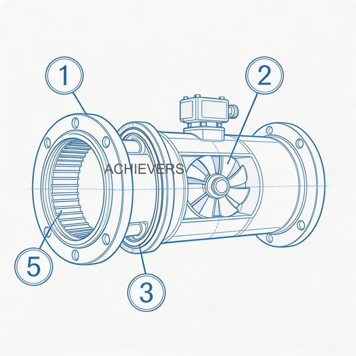
To troubleshoot effectively, one must understand the fundamental operating principle. A positive displacement flow meter consists of a precisely machined chamber housing a rotating or reciprocating mechanical device (like oval gears, nutating disks, or rotary vanes). As fluid flows through, it is restricted and trapped in the measurement cavity, creating fixed-volume discrete parcels. The rotation of these internal rotors is directly proportional to the volume of liquid moving through the meter.
The reliability of Positive Displacement Flow Meters depends entirely on the "capillary seal" formed between the moving parts and the meter casing. Process fluid viscosity plays a crucial role here; as viscosity increases, the fluid acts as a better seal, reducing bypass (slippage) and improving metering accuracy. A central electronic pulse transmitter or mechanical register counts the rotations to calculate total volume.
Engineering Formula: Flow Rate Calculation
The basic volumetric measurement is defined by the equation:
Q = V_c x N x E_v
Where:
- Q = Actual Flow Rate
- V_c = Volume of the measurement chamber (the discrete parcel)
- N = Rotational speed of the internal mechanism (RPM)
- E_v = Volumetric efficiency (accounts for slippage/bypass, typically approaching 1.0 in highly viscous fluids)
Technology Comparison Table
No single flow measurement technology is universal. Understanding how PD meters stack up against other technologies helps confirm if you have the right meter for your application, or if persistent issues are due to technology mismatch.
| Parameter | Positive Displacement | Turbine Flow Meters | Electromagnetic Flow Meters |
| — | — | — | — |
| Measurement Principle | Volumetric parsing | Velocity (Rotor speed) | Faraday's Law of Induction |
| Ideal Fluid | Viscous (Oils, Fats, Resins) | Clean, low-viscosity (Water, Light Diesel) | Conductive liquids (Water, Slurries) |
| Accuracy Effect from Viscosity | Improves with higher viscosity | Degrades with high viscosity | Independent of viscosity |
| Straight Pipe Requirement | None required | 10D upstream, 5D downstream | 5D upstream, 3D downstream |
| Pressure Drop | Moderate to High | Moderate | Zero (Unobstructed flow) |
| Turndown Ratio | Up to 100:1 | Typically 10:1 to 50:1 | Up to 1000:1 |
| Filtration Need | Critical (Small clearances) | High (Blade protection) | Low |
'When to Use This Technology' Decision Matrix
- Use Positive Displacement if: You are measuring highly viscous fluids (lubrication oils, printing inks, polymer additives), require extremely high accuracy (±0.1%) and repeatability (0.05%) for batching, and have tight installation spaces with no straight pipe runs available.
- Do NOT use Positive Displacement if: You are pumping abrasive slurries, fluids with high solid particulate content, or non-lubricating dry gases. Rapid wear of the precision-machined parts will immediately destroy the capillary seal and ruin accuracy.
2. Troubleshooting Matrix
When field conditions deviate from controlled baseline parameters, mechanical and electrical symptoms quickly emerge. Use this matrix to identify and resolve common faults.
| Symptom | Likely Cause | Diagnosis Steps | Corrective Action |
| — | — | — | — |
| Zero Reading (Flow active) | Sheared rotor shaft or broken coupling | Isolate meter, open housing, visually inspect gear synchronization. | Replace internal rotor/gear assembly. Ensure pressure spikes aren't exceeding limits. |
| Erratic Reading / Pulsation | Entrained air or gas bubbles in liquid flow | Check upstream lines for cavitation, vortexing in supply tanks, or pump leaks. | Install an air eliminator upstream of the meter. |
| Display Error / Drift (Low Accuracy) | "Slippage" due to internal wear or viscosity drop | Compare actual batch volume vs registered volume. Check fluid temperature. | Recalibrate if wear is minor. Replace meter if clearance gaps exceed manufacturer limits. |
| Leakage at Housing | O-ring failure or pressure hammer | Check pipeline for pressure spikes above 300 psig (nutating) or 1000 psig (rotary vane). | Replace seals/O-rings. Install pressure relief valves if water hammer is present. |
| Mechanical Noise / Grinding | Particulate contamination | Measure pressure drop across the upstream filter. Inspect internal chamber for scoring. | Clean or upgrade upstream strainer. Polish light scoring; replace heavily damaged rotors. |
| Power Fault / No Display | Moisture ingress in electronic transmitter | Check pulse transmitter housing for condensation, common during Indian monsoons. | Dry electronics. Reseal housing with industrial-grade silica gel and ensure IP67+ rated cable glands. |
| Sensor Fouling / Gear Jam | Solidified fluid or thermal shock | Check if polymer/fat process fluid cooled and hardened during a shutdown. | Apply heat tracing. Flush lines with solvent before shutting down pumps. |
| Output Signal Loss (PLC) | Wiring degradation or voltage fluctuation | Use multimeter to check for 4-20mA or pulse output at the transmitter terminals. | Replace damaged wiring. Install voltage stabilizers if site power is highly erratic. |
| Over-registration (Reads High) | Free air displacing liquid | Conduct a "bucket test" with a calibrated proving can. Check for foam at discharge. | Fix upstream suction leaks. Ensure air eliminator float valve is functioning correctly. |
| High Pressure Drop | Clogged strainer or viscous drag | Measure differential pressure across the meter. Check if fluid viscosity exceeds 25,000 cP. | Clean strainer baskets. If fluid is too cold, apply heat to lower viscosity to operational levels. |
3. Step-by-Step Field Diagnosis Procedure
When a meter is reported as "inaccurate," avoid immediate removal. Perform this rigorous in-situ diagnosis to pinpoint whether the fault is hydraulic, mechanical, or electronic.
- Safety and Isolation: Ensure the process line is depressurized and follow LOTO (Lockout/Tagout) procedures. If handling petrochemicals, verify PESO-compliant safety measures and use non-sparking tools.
- Verify Process Conditions: Cross-reference current fluid temperature and pressure against the meter's nameplate. High temperatures lower liquid viscosity, which can increase slippage and cause under-registration.
- Inspect the Upstream Strainer: Positive displacement meters have tiny clearances between rotors and housing. A clogged strainer causes cavitation, while a torn mesh allows debris to jam the rotors. Clean the filter system completely.
- Perform a Volumetric Proving Test: Use an officially calibrated and Legal Metrology certified proving can (e.g., 20L or 50L). Run fluid through the meter into the can at normal operating flow rates.
- Calculate the Error Percentage: Compare the meter's display to the proven volume. If the meter under-registers, suspect internal wear or bypass. If it over-registers, suspect air entrainment.
- Check Electronic Pulse Outputs: If using a digital register, attach an oscilloscope or frequency multimeter to the pulse output terminals. Ensure the pulse wave is a clean square wave without noise or voltage drops caused by poor grounding.
- Inspect the Measuring Chamber (Mechanical Diagnosis): If hydraulic and electrical checks pass, drain the meter and remove the front cover. Gently rotate the internal mechanism (oval gears, helical rotors, or vanes) by hand. It should move smoothly without binding or scraping.
- Evaluate Clearances: Use feeler gauges to check the gap between the rotors and the measurement chamber. If the clearance is significantly wider than factory specifications due to abrasive wear, recalibration via the K-factor will only be a temporary fix; hardware replacement is required.
4. Installation and Setup Errors That Cause Ongoing Problems
Many recurring accuracy issues stem from incorrect initial installation rather than equipment failure. Although PD meters are forgiving regarding straight pipe runs, they are highly sensitive to stress and fluid conditioning.
| Installation Error | Resulting Symptom | Engineering Correction |
| — | — | — |
| Missing Upstream Strainer | Rapid internal scoring and sudden gear jams. | Install a Y-strainer or basket strainer. Mesh size must suit the clearance gap of the specific PD meter model. |
| Overtightened Flange Bolts | Casing distortion causing rotors to bind or grind. | Torque flange bolts to exact manufacturer specifications using a star pattern to ensure even pressure. |
| Missing Air Eliminator | Meter registers air volume as liquid, over-charging customers. | Install an air/gas eliminator vessel upstream to vent entrained air before it reaches the measuring cavity. |
| Improper Orientation | Rotor shafts suffer uneven wear; potential gear slippage. | Orient the meter exactly as specified (usually with rotor shafts in a horizontal plane) to balance bearing loads. |
| Wrong Viscosity Calibration | K-factor programmed for water while measuring heavy oil. | Recalibrate the meter and adjust the electronic K-factor specifically for the operating viscosity of the process fluid. |
| Pipe Stress on Meter Body | Housing warpage leading to internal rubbing and high pressure drop. | Ensure upstream and downstream piping is fully supported by pipe hangers. The meter should not bear the weight of the piping network. |
Positive Displacement Flow Meter Technical Specifications
To properly troubleshoot, you must know the operational boundaries of your equipment. Below are standard specifications extracted from industrial PD meter technical sheets. Operating outside these bounds guarantees failure.
| Specification Parameter | Technical Rating / Capability |
| — | — |
| Base Accuracy | Up to ±0.1% of actual flow rate (improves with viscosity) |
| Repeatability | Up to 0.05% of reading |
| Maximum Size Range | Available in sizes up to 12 inches |
| Turndown Ratio | Can be as high as 100:1 |
| Power Requirement | None required for mechanical registers; 24VDC typical for pulse transmitters |
| Piping Requirements | Zero straight upstream/downstream pipe runs required |
| Max Pressure Limits | Nutating-disk: 150 – 300 psig <br> Rotary-vane: Up to 1,000 psig |
| Temperature Limits | Rotary-vane designs up to 350°F (176°C) |
| Viscosity Range | 1 to 25,000 centipoises (cP) |
5. Preventive Maintenance to Avoid Recurrence
Reactive maintenance in continuous process industries leads to unacceptable downtime. Implementing a preventive maintenance routine tailored to Indian site conditions will extend the lifespan of your meter and maintain its ±0.1% accuracy.
- Filter and Strainer Maintenance (Weekly/Monthly): Indian industrial fuels often contain high levels of suspended particulates. Monitor the differential pressure across upstream filters. Clean the basket when pressure drop exceeds 0.5 bar.
- Capillary Seal Protection (During Shutdowns): If the meter processes fluids that solidify at room temperature (like animal/vegetable fats, polymer additives, or heavy resins), flush the line with a compatible solvent before shutting down. Hardened fluids will snap rotor shafts upon restart.
- Electronics Protection (Pre-Monsoon): In high-humidity zones like coastal Gujarat or Maharashtra, inspect the IP rating of the pulse transmitter enclosure. Replace old silica gel packs, tighten cable glands, and ensure the O-ring seals on the transmitter head are lubricated and intact.
- Calibration Checks (Bi-Annually): Viscosity and clearances change over time. Run a proving test every six months. Adjust the mechanical calibrator or electronic K-factor to compensate for minor, expected wear.

6. When to Call Service vs. Fix Yourself
Knowing the limits of field repair prevents further damage to precision-machined instrumentation.
Fix Yourself:
- Cleaning upstream strainers and air eliminators.
- Drying out electronic enclosures and replacing terminal wiring.
- Adjusting the electronic K-factor in the PLC or local display to correct for minor accuracy drift (e.g., a consistent 1% under-registration).
- Replacing external O-rings to stop minor flange leaks.
Call Factory Service:
- Significant internal wear: If the meter is under-registering by large margins (>5%) despite fluid viscosity remaining high, the internal measuring chamber or rotors are severely worn. Machining or replacing these parts requires factory calibration.
- Custody Transfer Disputes: If the meter is used for commercial billing (Legal Metrology compliant applications) and is out of spec, recalibration must often be performed by certified technicians with traceable master meters.
- Mechanical Binding: If the rotors are jammed and do not turn freely after cleaning out debris, the main shaft or bearings are likely bent.
FAQ
Q: Why does my PD meter read accurately in winter but lose accuracy in the Indian summer?
A: High ambient and process temperatures lower the viscosity of your fluid. Because PD meters rely on process fluid to create a capillary seal between moving parts, a drop in viscosity increases slippage (bypass), leading to under-registration of flow.
Q: Do I need a straight pipe run to install this meter?
A: No. Unlike velocity-based meters (such as turbine or ultrasonic meters) which require fully developed flow profiles, PD meters do not necessitate straight upstream and downstream pipe runs, making them ideal for cramped industrial layouts.
Q: Can I use a PD meter to measure borewell water or slurries?
A: It is highly discouraged. PD meters have very small clearances between their precision-machined parts. Abrasive fluids, fine sand from borewells, or slurries will cause rapid wear, destroying the meter's accuracy very quickly. Consider an electromagnetic flow meter instead.
Q: My mechanical register is clicking, but the totals aren't advancing. What is wrong?
A: The magnetic coupling or mechanical gearing connecting the internal measuring rotor to the external register has likely sheared or decoupled. The meter must be isolated and the coupling assembly inspected and replaced.
Q: How frequently should we calibrate our PD meters used for diesel dispensing?
A: In India, for any commercial or custody transfer application, calibration is mandated annually by the Department of Legal Metrology. For internal plant accounting, performing a bucket proving test every 6 months is recommended to ensure drift remains within ±0.1%.
Q: What is the maximum viscosity a rotary vane meter can handle?
A: Standard industrial rotary-vane meters can comfortably handle viscosity limits ranging between 1 and 25,000 centipoises (cP), provided the pumping system can maintain adequate flow pressure without causing extreme differential pressure across the meter.
Q: Is it normal for a PD meter to cause a pressure drop in the pipeline?
A: Yes. Because the fluid must perform mechanical work to push the rotors or disks to measure the flow, a moderate pressure drop is inherent to the design. If the pressure drop spikes suddenly, check your upstream filter for blockages.
If you are experiencing persistent measurement drift, batching inconsistencies, or require a customized fluid measurement solution tailored for harsh Indian industrial conditions, contact Lumen Instruments today. Share your fluid type, expected flow rate, maximum operating temperature, and site conditions, and our engineering team will help you specify, troubleshoot, or upgrade your Positive Displacement Flow Meters for zero-error operations.